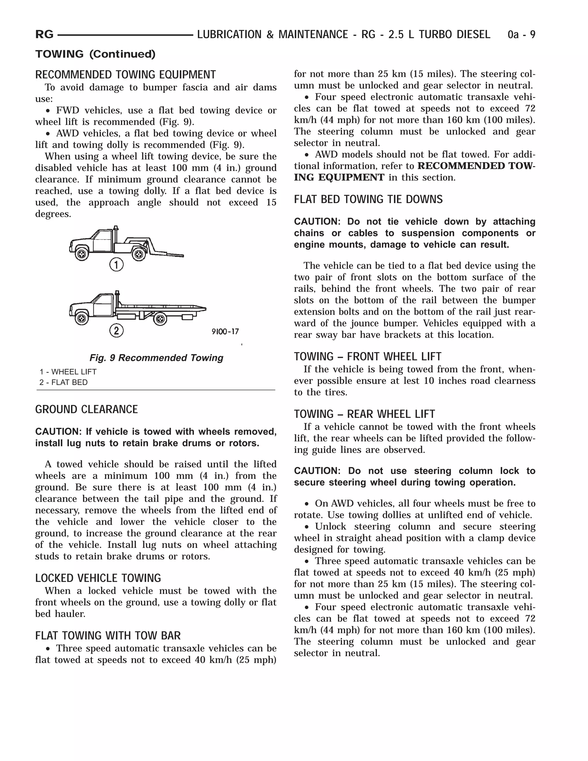
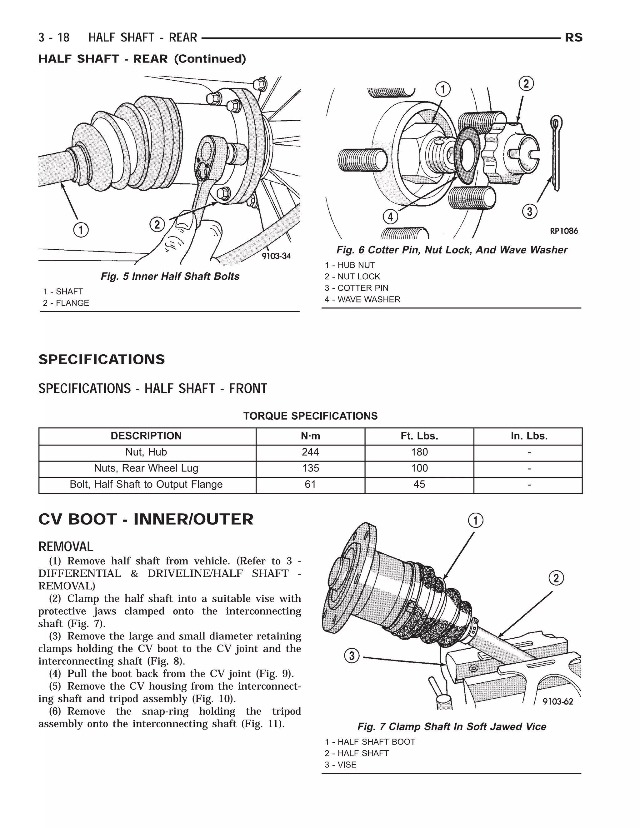
GROUP TAB LOCATOR
IN Introduction
INa Introduction
0 Lubrication & Maintenance
0a Lubrication & Maintenance
2 Suspension
2a Suspension
3 Differential & Driveline
5 Brakes
5a Brakes
6a Clutch
7 Cooling
7a Cooling
8A Audio
8Aa Audio
8B Chime/Buzzer
8Ba Chime/Buzzer
8E Electronic Control Modules
8F Engine Systems
8Fa Engine Systems
8G Heated Systems
8H Horn
8I Ignition Control
8J Instrument Cluster
8Ja Instrument Cluster
8L Lamps
8La Lamps
8M Message Systems
8N Power Systems
8Na Power Systems
8O Restraints
8P Speed Control
8Q Vehicle Theft Security
8R Wipers/Washers
8Wa Wiring
9 Engine
9a Engine
11 Exhaust System
11a Exhaust System
13 Frame & Bumpers
14 Fuel System
14a Fuel System
19 Steering
19a Steering
21 Transmission/Transaxle
21a Transmission/Transaxle
22 Tires/Wheels
23 Body
24 Heating & Air Conditioning
24a Heating & Air Conditioning
25 Emissions Control
25a Emissions Control
Service Manual Comment Forms
INTRODUCTION
TABLE OF CONTENTS
page page
VEHICLE SAFETY CERTIFICATION LABEL
DESCRIPTION . . . . . . . . . . . . . . . . . . . . . . . . . . . . 1
VEHICLE IDENTIFICATION NUMBER
DESCRIPTION . . . . . . . . . . . . . . . . . . . . . . . . . . . . 1
VECI LABEL
DESCRIPTION . . . . . . . . . . . . . . . . . . . . . . . . . . . . 3
BODY CODE PLATE
DESCRIPTION . . . . . . . . . . . . . . . . . . . . . . . . . . . . 3
INTERNATIONAL SYMBOLS
DESCRIPTION . . . . . . . . . . . . . . . . . . . . . . . . . . . . 4
FASTENER IDENTIFICATION
DESCRIPTION . . . . . . . . . . . . . . . . . . . . . . . . . . . . 5
FASTENER USAGE
DESCRIPTION . . . . . . . . . . . . . . . . . . . . . . . . . . . . 5
METRIC SYSTEM
DESCRIPTION . . . . . . . . . . . . . . . . . . . . . . . . . . . . 8
TORQUE REFERENCES
DESCRIPTION . . . . . . . . . . . . . . . . . . . . . . . . . . . 10
VEHICLE SAFETY
CERTIFICATION LABEL
DESCRIPTION
A vehicle safety certification label (Fig. 1) is located
on the rearward facing of the driver’s door. This label
indicates date of manufacture (month and year), Gross
Vehicle Weight Rating (GVWR), Gross Axle Weight
Rating (GAWR) front, Gross Axle Weight Rating
(GAWR) rear and the Vehicle Identification Number
(VIN). The Month, Day and Hour (MDH) of manufac-
ture is also included.
When it is necessary to contact the manufacturer
regarding service or warranty, the information on the
Vehicle Safety Certification Label would be required.
VEHICLE IDENTIFICATION
NUMBER
DESCRIPTION
The Vehicle Identification Number (VIN) can be
viewed through the windshield at the upper left cor-
ner of the instrument panel, near the left windshield
pillar (Fig. 2). The VIN consists of 17 characters in a
combination of letters and numbers that provide spe-
cific information about the vehicle. Refer to VIN Code
Breakdown Chart for decoding information.
To protect the consumer from theft and possible
fraud the manufacturer is required to include a Check
Digit at the ninth position of the Vehicle Identification
Number. The check digit is used by the manufacturer
and government agencies to verify the authenticity of
the vehicle and official documentation. The formula to
use the check digit is not released to the general public.
Fig. 1 Vehicle Safety Certification Label
Fig. 2 Vehicle Identification Number (VIN Plate)
1 - DEFROSTER OUTLET
2 - VIN #
3 - HEATED WINDSHIELD GRID
RS INTRODUCTION 1
VIN CODE BREAKDOWN CHART
POSITION INTERPRETATION CODE = DESCRIPTION
1 Country of Origin 1 = Built in the United States by DaimlerChrysler
2 = Built in Canada by DaimlerChrysler Canada
Inc.
2 Make B = Dodge
C = Chrysler
3 Vehicle Type 4 = Multipurpose Pass. Vehicle Less Side Air
Bags
8 = Multipurpose Pass. Vehicle With Side Air
Bags
4 Gross Vehicle Weight Rating G = 2268 - 2721 kg. (5001 - 6000 lbs.)
5 Car Line P = Chrysler, Town & Country - FWD
P = Dodge, Caravan/Grand Caravan - FWD
T = Chrysler, Town & Country - AWD
T = Dodge, Grand Caravan - AWD
J = Chrysler, Voyager/Grand Voyager - FWD
6 Series 2 = Low Line
4 = High Line
5 = Premium
6 = Sport
7 = Special
7 Body Style 4 = Long Wheel Base
5 = Short Wheel Base
8 Engine B = 2.4 L 4 cyl. MPI 16-VALVE DOHC
G = 3.3 L 6 cyl. Ethanol Flexible Fuel MPI
R = 3.3 L 6 cyl. Gas MPI
L = 3.8 L 6 cyl. Gas MPI
9 Check Digit See explanation in this section.
10 Model Year 1= 2001
11 Assembly Plant B = St. Louis South
R = Windsor
12 through 17 Sequence Number A six digit number assigned by assembly plant.
2 INTRODUCTION RS
VEHICLE IDENTIFICATION NUMBER (Continued)
VECI LABEL
DESCRIPTION
All models have a Vehicle Emission Control Infor-
mation (VECI) Label. Chrysler permanently attaches
the label in the engine compartment. It cannot be
removed without defacing information and destroying
the label.
The label contains the vehicle’s emission specifica-
tions and vacuum hose routings. All hoses must be
connected and routed according to the label.
BODY CODE PLATE
DESCRIPTION
The Body Code Plate (Fig. 3) is located in the
engine compartment on the radiator closure panel
crossmember. There are seven lines of information on
the body code plate. Lines 4, 5, 6, and 7 are not used
to define service information. Information reads from
left to right, starting with line 3 in the center of the
plate to line 1 at the bottom of the plate.
BODY CODE PLATE – LINE 3
DIGITS 1 THROUGH 12
Vehicle Order Number
DIGITS 13 THROUGH 17
Open space
DIGITS 18 AND 19
Vehicle Shell Line
• NS
DIGIT 20
Carline
FWD
• H = Plymouth
• K = Dodge
• Y = Chrysler
AWD
• C = Chrysler
• D = Dodge
• P = Plymouth
DIGIT 21
Price Class
• H = Highline
• L = Lowline
• P = Premium
• S = Luxury
• X = Premium
DIGITS 22 AND 23
Body Type
• 52 = Short Wheel Base
• 53 = Long Wheel Base
BODY CODE PLATE LINE 2
DIGITS 1, 2 AND 3
Paint procedure
DIGIT 4
Open Space
DIGITS 5 THROUGH 7
Primary paint
Refer to Group 23, Body for color codes.
DIGIT 8 AND 9
Open Space
DIGITS 10 THROUGH 12
Secondary Paint
Fig. 3 Body Code Plate
1 - PRIMARY PAINT
2 - SECONDARY PAINT
3 - VINYL ROOF
4 - VEHICLE ORDER NUMBER
5 - CAR LINE SHELL
6 - PAINT PROCEDURE
7 - ENGINE
8 - TRIM
9 - TRANSMISSION
10 - MARKET
11 - VIN
RS INTRODUCTION 3
DIGIT 13 AND 14
Open Space
DIGITS 15 THROUGH 18
Interior Trim Code
DIGIT 19
Open Space
DIGITS 20, 21, AND 22
Engine Code
• EDZ = 2.4 L 4 cyl. DOHC Gasoline
• EFA = 3.0 L 6 cyl. Gasoline
• EGA = 3.3 L 6 cyl. Gasoline
• EGH = 3.8 L 6 cyl. Gasoline
• EGM = 3.3 L 6 cyl. Ethanol Flexible Fuel
DIGIT 23
Open Space
BODY CODE PLATE LINE 1
DIGITS 1, 2, AND 3
Transaxle Codes
• DGB = 41TH 4-speed Automatic Transaxle
• DGL = 41TE 4-speed Electronic Automatic Tran-
saxle
• DGM = 31TH 3-speed Automatic Transaxle
DIGIT 4
Open Space
DIGIT 5
Market Code
• C = Canada
• B = International
• M = Mexico
• U = United States
DIGIT 6
Open Space
DIGITS 7 THROUGH 23
Vehicle Identification Number
• Refer to Vehicle Identification Number (VIN)
paragraph for proper breakdown of VIN code.
IF TWO BODY CODE PLATES ARE REQUIRED
The last code shown on either plate will be fol-
lowed by END. When two plates are required, the
last code space on the first plate will indicate (CTD)
When a second plate is required, the first four
spaces of each line will not be used due to overlap of
the plates.
INTERNATIONAL SYMBOLS
DESCRIPTION
The graphic symbols illustrated in the following
International Control and Display Symbols Chart are
used to identify various instrument controls. The
symbols correspond to the controls and displays that
are located on the instrument panel.
4 INTRODUCTION RS
BODY CODE PLATE (Continued)
FASTENER IDENTIFICATION
DESCRIPTION
The SAE bolt strength grades range from grade 2
to grade 8. The higher the grade number, the greater
the bolt strength. Identification is determined by the
line marks on the top of each bolt head. The actual
bolt strength grade corresponds to the number of line
marks plus 2. The most commonly used metric bolt
strength classes are 9.8 and 10.9. The metric
strength class identification number is imprinted on
the head of the bolt. The higher the class number,
the greater the bolt strength. Some metric nuts are
imprinted with a single-digit strength class on the
nut face. Refer to the Fastener Identification and
Fastener Strength Charts.
FASTENER USAGE
DESCRIPTION - FASTENER USAGE
WARNING: USE OF AN INCORRECT FASTENER
MAY RESULT IN COMPONENT DAMAGE OR PER-
SONAL INJURY.
Figure art, specifications and torque references in
this Service Manual are identified in metric and SAE
format.
During any maintenance or repair procedures, it is
important to salvage all fasteners (nuts, bolts, etc.)
for reassembly. If the fastener is not salvageable, a
fastener of equivalent specification must be used.
International Symbols
1 High Beam 13 Rear Window Washer
2 Fog Lamps 14 Fuel
3 Headlamp, Parking Lamps, Panel Lamps 15 Engine Coolant Temperature
4 Turn Warning 16 Battery Charging Condition
5 Hazard Warning 17 Engine Oil
6 Windshield Washer 18 Seat Belt
7 Windshield Wiper 19 Brake Failure
8 Windshield Wiper and Washer 20 Parking Brake
9 Windscreen Demisting and Defrosting 21 Front Hood
10 Ventilating Fan 22 Rear hood (Decklid)
11 Rear Window Defogger 23 Horn
12 Rear Window Wiper 24 Lighter
RS INTRODUCTION 5
INTERNATIONAL SYMBOLS (Continued)
FASTENER IDENTIFICATION
6 INTRODUCTION RS
FASTENER USAGE (Continued)
FASTENER STRENGTH
RS INTRODUCTION 7
FASTENER USAGE (Continued)
DESCRIPTION - THREADED HOLE REPAIR
Most stripped threaded holes can be repaired using
a Helicoil௡. Follow the vehicle or Helicoil௡ recommen-
dations for application and repair procedures.
METRIC SYSTEM
DESCRIPTION - METRIC SYSTEM
The metric system is based on quantities of one,
ten, one hundred, one thousand and one million .
The following chart will assist in converting metric
units to equivalent English and SAE units, or vise
versa.
CONVERSION FORMULAS AND EQUIVALENT VALUES
MULTIPLY BY TO GET MULTIPLY BY TO GET
in-lbs x 0.11298 = Newton Meters (N·m) N·m x 8.851 = in-lbs
ft-lbs x 1.3558 = Newton Meters (N·m) N·m x 0.7376 = ft-lbs
Inches Hg
(60° F)
x 3.377 = Kilopascals (kPa) kPa x 0.2961 = Inches Hg
psi x 6.895 = Kilopascals (kPa) kPa x 0.145 = psi
Inches x 25.4 = Millimeters (mm) mm x 0.03937 = Inches
Feet x 0.3048 = Meters (M) M x 3.281 = Feet
Yards x 0.9144 = Meters M x 1.0936 = Yards
mph x 1.6093 = Kilometers/Hr. (Km/h) Km/h x 0.6214 = mph
Feet/Sec x 0.3048 = Meters/Sec (M/S) M/S x 3.281 = Feet/Sec
mph x 0.4470 = Meters/Sec (M/S) M/S x 2.237 = mph
Kilometers/
Hr. (Km/h)
x 0.27778 = Meters/Sec (M/S) M/S x 3.600 Kilometers/Hr.
(Km/h)
COMMON METRIC EQUIVALENTS
1 inch = 25 Millimeters 1 Cubic Inch = 16 Cubic Centimeters
1 Foot = 0.3 Meter 1 Cubic Foot = 0.03 Cubic Meter
1 Yard = 0.9 Meter 1 Cubic Yard = 0.8 Cubic Meter
1 Mile = 1.6 Kilometers
Refer to the Metric Conversion Chart to convert
torque values listed in metric Newton- meters (N·m).
Also, use the chart to convert between millimeters
(mm) and inches (in.)
8 INTRODUCTION RS
FASTENER USAGE (Continued)
METRIC CONVERSION CHART
RS INTRODUCTION 9
METRIC SYSTEM (Continued)
TORQUE REFERENCES
DESCRIPTION
Individual Torque Charts appear within many or
the Groups. Refer to the Standard Torque Specifica-
tions Chart for torque references not listed in the
individual torque charts.
TORQUE SPECIFICATIONS
10 INTRODUCTION RS
INTRODUCTION
TABLE OF CONTENTS
page page
BODY CODE PLATE
DESCRIPTION . . . . . . . . . . . . . . . . . . . . . . . . . . . . 1
FASTENER IDENTIFICATION
DESCRIPTION . . . . . . . . . . . . . . . . . . . . . . . . . . . . 2
FASTENER USAGE
DESCRIPTION . . . . . . . . . . . . . . . . . . . . . . . . . . . . 5
THREADED HOLE REPAIR
DESCRIPTION . . . . . . . . . . . . . . . . . . . . . . . . . . . . 5
INTERNATIONAL VEHICLE CONTROL &
DISPLAY SYMBOLS
DESCRIPTION . . . . . . . . . . . . . . . . . . . . . . . . . . . . 5
METRIC SYSTEM
DESCRIPTION . . . . . . . . . . . . . . . . . . . . . . . . . . . . 6
TORQUE REFERENCES
DESCRIPTION . . . . . . . . . . . . . . . . . . . . . . . . . . . . 8
VEHICLE IDENTIFICATION NUMBER
DESCRIPTION . . . . . . . . . . . . . . . . . . . . . . . . . . . . 9
VEHICLE SAFETY CERTIFICATION LABEL
DESCRIPTION . . . . . . . . . . . . . . . . . . . . . . . . . . . 10
E-MARK LABEL
DESCRIPTION . . . . . . . . . . . . . . . . . . . . . . . . . . . 10
VECI LABEL
DESCRIPTION . . . . . . . . . . . . . . . . . . . . . . . . . . . 10
MANUFACTURE PLATE
DESCRIPTION . . . . . . . . . . . . . . . . . . . . . . . . . . . 10
BODY CODE PLATE
DESCRIPTION
The Body Code Plate (Fig. 1) is located in the
engine compartment on the radiator closure panel
crossmember. There are seven lines of information on
the body code plate. Lines 4, 5, 6, and 7 are not used
to define service information. Information reads from
left to right, starting with line 3 in the center of the
plate to line 1 at the bottom of the plate.
BODY CODE PLATE – LINE 3
DIGITS 1 THROUGH 12
Vehicle Order Number
DIGITS 13 THROUGH 17
Open space
DIGITS 18 AND 19
Vehicle Shell Line
• RG
DIGIT 20
Carline
FWD
• Y = Chrysler
AWD
• C = Chrysler
Fig. 1 BODY CODE PLATE
1 - PRIMARY PAINT
2 - SECONDARY PAINT
3 - VINYL ROOF
4 - VEHICLE ORDER NUMBER
5 - CAR LINE SHELL
6 - PAINT PROCEDURE
7 - ENGINE
8 - TRIM
9 - TRANSMISSION
10 - MARKET
11 - VIN
RG INTRODUCTION 1a
DIGIT 21
Price Class
• H = Highline
• L = Lowline
• P = Premium
• S = Luxury
• X = Premium
DIGITS 22 AND 23
Body Type
• 52 = Short Wheel Base
• 53 = Long Wheel Base
BODY CODE PLATE LINE 2
DIGITS 1, 2 AND 3
Paint procedure
DIGIT 4
Open Space
DIGITS 5 THROUGH 7
Primary paint(Refer to 23 - BODY/PAINT - SPEC-
IFICATIONS).
DIGIT 8 AND 9
Open Space
DIGITS 10 THROUGH 12
Secondary Paint
DIGIT 13 AND 14
Open Space
DIGITS 15 THROUGH 18
Interior Trim Code
DIGIT 19
Open Space
DIGITS 20, 21, AND 22
Engine Code
• ENC = 2.5 L 4 cyl. Turbo Diesel
DIGIT 23
Open Space
BODY CODE PLATE LINE 1
DIGITS 1, 2, AND 3
Transaxle Codes
• DGB = 41TH 4-speed Automatic Transaxle
• DGL = 41TE 4-speed Electronic Automatic
Transaxle
• DGM = 31TH 3-speed Automatic Transaxle
DIGIT 4
Open Space
DIGIT 5
Market Code
• C = Canada
• B = International
• M = Mexico
• U = United States
DIGIT 6
Open Space
DIGITS 7 THROUGH 23
Vehicle Identification Number
• Refer to Vehicle Identification Number (VIN)
paragraph for proper breakdown of VIN code.
IF TWO BODY CODE PLATES ARE REQUIRED
The last code shown on either plate will be fol-
lowed by END. When two plates are required, the
last code space on the first plate will indicate (CTD)
When a second plate is required, the first four
spaces of each line will not be used due to overlap of
the plates.
FASTENER IDENTIFICATION
DESCRIPTION
The SAE bolt strength grades range from grade 2
to grade 8. The higher the grade number, the greater
the bolt strength. Identification is determined by the
line marks on the top of each bolt head. The actual
bolt strength grade corresponds to the number of line
marks plus 2. The most commonly used metric bolt
strength classes are 9.8 and 10.9. The metric
strength class identification number is imprinted on
the head of the bolt. The higher the class number,
the greater the bolt strength. Some metric nuts are
imprinted with a single-digit strength class on the
nut face. Refer to the Fastener Identification and
Fastener Strength Charts (Fig. 2) and (Fig. 3).
2a INTRODUCTION RG
BODY CODE PLATE (Continued)
Fig. 2 FASTENER IDENTIFICATION
RG INTRODUCTION 3a
FASTENER IDENTIFICATION (Continued)
Fig. 3 FASTENER STRENGTH
4a INTRODUCTION RG
FASTENER IDENTIFICATION (Continued)
FASTENER USAGE
DESCRIPTION
WARNING: USE OF AN INCORRECT FASTENER
MAY RESULT IN COMPONENT DAMAGE OR PER-
SONAL INJURY.
Figure art, specifications and torque references in
this Service Manual are identified in metric and SAE
format.
During any maintenance or repair procedures, it is
important to salvage all fasteners (nuts, bolts, etc.)
for reassembly. If the fastener is not salvageable, a
fastener of equivalent specification must be used.
THREADED HOLE REPAIR
DESCRIPTION
Most stripped threaded holes can be repaired using
a Helicoil௡. Follow the vehicle or Helicoil௡ recommen-
dations for application and repair procedures.
INTERNATIONAL VEHICLE
CONTROL & DISPLAY
SYMBOLS
DESCRIPTION
The graphic symbols illustrated in the following
International Control and Display Symbols Chart
(Fig. 4) are used to identify various instrument con-
trols. The symbols correspond to the controls and dis-
plays that are located on the instrument panel.
Fig. 4 INTERNATIONAL CONTROL AND DISPLAY SYMBOLS
1 High Beam 13 Rear Window Washer
2 Fog Lamps 14 Fuel
3 Headlamp, Parking Lamps, Panel Lamps 15 Engine Coolant Temperature
4 Turn Warning 16 Battery Charging Condition
5 Hazard Warning 17 Engine Oil
6 Windshield Washer 18 Seat Belt
7 Windshield Wiper 19 Brake Failure
8 Windshield Wiper and Washer 20 Parking Brake
9 Windscreen Demisting and Defrosting 21 Front Hood
10 Ventilating Fan 22 Rear hood (Decklid)
11 Rear Window Defogger 23 Horn
12 Rear Window Wiper 24 Lighter
RG INTRODUCTION 5a
METRIC SYSTEM
DESCRIPTION
The metric system is based on quantities of one,
ten, one hundred, one thousand and one million.
The following chart will assist in converting metric
units to equivalent English and SAE units, or vise
versa.
CONVERSION FORMULAS AND EQUIVALENT VALUES
MULTIPLY BY TO GET MULTIPLY BY TO GET
in-lbs x
0.11298
= Newton Meters
(N·m)
N·m x 8.851 = in-lbs
ft-lbs x
1.3558
= Newton Meters
(N·m)
N·m x
0.7376
= ft-lbs
Inches Hg (60° F) x 3.377 = Kilopascals (kPa) kPa x
0.2961
= Inches Hg
psi x 6.895 = Kilopascals (kPa) kPa x 0.145 = psi
Inches x 25.4 = Millimeters (mm) mm x
0.03937
= Inches
Feet x
0.3048
= Meters (M) M x 3.281 = Feet
Yards x
0.9144
= Meters M x
1.0936
= Yards
mph x
1.6093
= Kilometers/Hr.
(Km/h)
Km/h x
0.6214
= mph
Feet/Sec x
0.3048
= Meters/Sec (M/S) M/S x 3.281 = Feet/Sec
mph x
0.4470
= Meters/Sec (M/S) M/S x 2.237 = mph
Kilometers/Hr. (Km/h) x
0.27778
= Meters/Sec (M/S) M/S x 3.600 Kilometers/Hr. (Km/h)
COMMON METRIC EQUIVALENTS
1 inch = 25 Millimeters 1 Cubic Inch = 16 Cubic Centimeters
1 Foot = 0.3 Meter 1 Cubic Foot = 0.03 Cubic Meter
1 Yard = 0.9 Meter 1 Cubic Yard = 0.8 Cubic Meter
1 Mile = 1.6 Kilometers
Refer to the Metric Conversion Chart to convert
torque values listed in metric Newton- meters (N·m).
Also, use the chart to convert between millimeters
(mm) and inches (in.)
6a INTRODUCTION RG
METRIC CONVERSION CHART
RG INTRODUCTION 7a
METRIC SYSTEM (Continued)
TORQUE REFERENCES
DESCRIPTION
Individual Torque Charts appear within many or
the Groups. Refer to the Standard Torque Specifica-
tions Chart for torque references not listed in the
individual torque charts.
TORQUE SPECIFICATIONS
8a INTRODUCTION RG
VEHICLE IDENTIFICATION
NUMBER
DESCRIPTION
The Vehicle Identification Number (VIN) can be
viewed through the windshield at the upper left cor-
ner of the instrument panel, near the left windshield
pillar (Fig. 5). The VIN consists of 17 characters in a
combination of letters and numbers that provide spe-
cific information about the vehicle. Refer to VIN
Code Breakdown Chart for decoding information.
To protect the consumer from theft and possible
fraud the manufacturer is required to include a
Check Digit at the ninth position of the Vehicle Iden-
tification Number. The check digit is used by the
manufacturer and government agencies to verify the
authenticity of the vehicle and official documenta-
tion. The formula to use the check digit is not
released to the general public.
VIN CODE BREAKDOWN CHART
POSITION INTERPRETATION CODE = DESCRIPTION
1 Country of Origin 1 = Built in the Graz Austria by DaimlerChrysler
2 Make C = Chrysler
3 Vehicle Type 4 = Multipurpose Pass. Vehicle Less Side Air Bags
8 = Multipurpose Pass. Vehicle With Side Air Bags
4 Gross Vehicle Weight
Rating
G = 2268 - 2721 kg. (5001 - 6000 lbs.)
5 Car Line Y = Voyager/Grand Voyager - FWD Left Hand Drive
C = Voyager/Grand Voyager - AWD Left Hand Drive
H = Voyager/Grand Voyager - FWD Right Hand Drive
K = Voyager/Grand Voyager - AWD Right Hand Drive
I = Caravan FWD
6 Series 2 = Low Line
4 = High Line
5 = Premium
6 = Sport
7 = Special
7 Body Style 4 = Long Wheel Base
5 = Short Wheel Base
8 Engine B = 2.4 L 4 cyl. MPI 16 - VALVE DOHC
R = 3.3 L 6 cyl. Gasoline MPI
M = 2.5 L 4 cyl. Turbo Diesel
9 Check Digit See explanation in this section.
10 Model Year 1= 2001
11 Assembly Plant U = Graz Austria
12 through 17 Sequence Number A six digit number assigned by assembly plant.
Fig. 5 Vehicle Identification Number (VIN Plate)
1 - DEFROSTER OUTLET
2 - VIN #
3 - HEATED WINDSHIELD GRID
RG INTRODUCTION 9a
VEHICLE SAFETY
CERTIFICATION LABEL
DESCRIPTION
A vehicle safety certification label (Fig. 6) is located
on the rearward facing of the driver’s door. This label
indicates date of manufacture (month and year),
Gross Vehicle Weight Rating (GVWR), Gross Axle
Weight Rating (GAWR) front, Gross Axle Weight Rat-
ing (GAWR) rear and the Vehicle Identification Num-
ber (VIN). The Month, Day and Hour (MDH) of
manufacture is also included.
When it is necessary to contact the manufacturer
regarding service or warranty, the information on the
Vehicle Safety Certification Label would be required.
E-MARK LABEL
DESCRIPTION
An E-mark Label (Fig. 7) is located on the rear
shut face of the driver’s door. The label contains the
following information:
• Date of Manufacture
• Month-Day-Hour (MDH)
• Vehicle Identification Number (VIN)
• Country Codes
• Regulation Number
• Regulation Amendment Number
• Approval Number
VECI LABEL
DESCRIPTION
All models have a Vehicle Emission Control Infor-
mation (VECI) Label. Chrysler permanently attaches
the label in the engine compartment. It cannot be
removed without defacing information and destroying
the label.
The label contains the vehicle’s emission specifica-
tions and vacuum hose routings. All hoses must be
connected and routed according to the label.
MANUFACTURE PLATE
DESCRIPTION
The Manufacturer Plate (Fig. 8) is located in the
engine compartment on the passenger side strut
tower. The plate contains five lines of information:
• Vehicle Identification Number (VIN)
• Gross Vehicle Mass (GVM)
• Gross Train Mass (GTM)
• Gross Front Axle Rating (GFAR)
• Gross Rear Axle Rating (GRAR)
Fig. 6 Vehicle Safety Certification Label
Fig. 7 E-Mark Label
1 - Country Code
2 - Regulation Number
3 - Approval Number
4 - Amendment Number
Fig. 8 Manufacturer Plate
10a INTRODUCTION RG
LUBRICATION & MAINTENANCE
TABLE OF CONTENTS
page page
LUBRICATION & MAINTENANCE
SPECIFICATIONS . . . . . . . . . . . . . . . . . . . . . . . . . 1
INTERNATIONAL SYMBOLS
DESCRIPTION . . . . . . . . . . . . . . . . . . . . . . . . . . . . 1
PARTS & LUBRICANT RECOMMENDATION
STANDARD PROCEDURE . . . . . . . . . . . . . . . . . . . 2
LUBRICANT CLASSIFICATIONS. . . . . . . . . . . . . 2
PARTS AND LUBRICANT
RECOMMENDATIONS . . . . . . . . . . . . . . . . . . . . 2
FLUID TYPES
DESCRIPTION . . . . . . . . . . . . . . . . . . . . . . . . . . . . 3
OPERATION . . . . . . . . . . . . . . . . . . . . . . . . . . . . . 7
FLUID FILL/CHECK LOCATIONS
DESCRIPTION . . . . . . . . . . . . . . . . . . . . . . . . . . . . 7
MAINTENANCE SCHEDULES
DESCRIPTION . . . . . . . . . . . . . . . . . . . . . . . . . . . . 7
HOISTING
STANDARD PROCEDURE . . . . . . . . . . . . . . . . . . 16
HOISTING . . . . . . . . . . . . . . . . . . . . . . . . . . . . 16
JUMP STARTING
STANDARD PROCEDURE . . . . . . . . . . . . . . . . . . 16
JUMP STARTING . . . . . . . . . . . . . . . . . . . . . . . 16
TOWING
STANDARD PROCEDURE . . . . . . . . . . . . . . . . . . 17
TOWING RECOMMENDATIONS . . . . . . . . . . . . 17
LUBRICATION &
MAINTENANCE
SPECIFICATIONS
SPECIFICATIONS - FLUID CAPACITIES
DESCRIPTION SPECIFICATION
Fuel Tank 75 L (20 gal.)
Engine Oil* - 2.4L 4.7 L (5.0 qts.)
Engine Oil* - 3.3/3.8L 4.0 L (4.5 qts.)
Cooling System** - 2.4L 10.7 L (11.4 qts.)
Cooling System** -
3.3/3.8L without Rear
Heater
12.6 L (13.4 qts.)
Cooling System** -
3.3/3.8L with Rear Heater
15.4 L (16.3 qts.)
Automatic Transaxle -
Service Fill
3.8 L (4.0 qts.)
Automatic Transaxle -
31TH Overhaul Fill
8.6 L (9.1 qts.)
Automatic Transaxle -
41TE Overhaul Fill
9.2 L (9.7 qts.)
AWD Power Transfer Unit 1.15 L (2.4 pts.)
Power Steering 1.2 L (2.5 pts.)
AWD Bi-directional
Overrunning Clutch
0.575 L (1.22 pts.)
DESCRIPTION SPECIFICATION
AWD Rear Carrier 0.7 L (1.48 pts.)
*(includes oil filter)
**(includes heater and recovery/reserve bottle)
INTERNATIONAL SYMBOLS
DESCRIPTION
DaimlerChrysler Corporation uses international
symbols to identify engine compartment lubricant
and fluid check and fill locations (Fig. 1).
Fig. 1 International Symbols
RS LUBRICATION & MAINTENANCE 0 - 1
PARTS & LUBRICANT
RECOMMENDATION
STANDARD PROCEDURE - Classification of
Lubricants
Only lubricants that bear designations defined by
the following organization should be used to service a
DaimlerChrysler vehicle.
• Society of Automotive Engineers (SAE)
• American Petroleum Institute (API) (Fig. 2)
• National Lubricating Grease Institute (NLGI)
(Fig. 3)
ENGINE OIL
SAE VISCOSITY RATING INDICATES ENGINE OIL VISCOSITY
An SAE viscosity grade is used to specify the vis-
cosity of engine oil. Engine oils also have multiple
viscosities. These are specified with a dual SAE vis-
cosity grade which indicates the cold-to-hot tempera-
ture viscosity range.
• SAE 30 = single grade engine oil.
• SAE 10W-30 = multiple grade engine oil.Daim-
lerChrysler only recommends multiple grade engine
oils.
API QUALITY CLASSIFICATION
This symbol (Fig. 2) on the front of an oil container
means that the oil has been certified by the Ameri-
can Petroleum Institute (API) to meet all the lubri-
cation requirements specified by DaimlerChrysler.
Refer to Group 9, Engine for gasoline engine oil
specification.
FLEXIBLE FUEL ENGINE OIL – 3.3L ENGINE
Engine Oil Selection for Operating on E-85
Fuel If vehicle operates on E-85 fuel either full or
part-time, use only Mopar௡ Flexible Fuel SAE 5W-30
engine oil or an equivalent that meets
DaimlerChrysler Standard MS-9214. Equivalent com-
mercial Flexible Fuel engine oils may be labeled as
Multi-Fuel, Variable Fuel, Flexible Fuel, etc. These
engine oils are preferred for use in Flexible Fuel
engines.
CAUTION: If Flexible Fuel engine oil is not used
when using E-85 fuel, engine wear or damage may
result.
GEAR LUBRICANTS
SAE ratings also apply to multiple grade gear
lubricants. In addition, API classification defines the
lubricants usage.
LUBRICANTS AND GREASES
Lubricating grease is rated for quality and usage
by the NLGI. All approved products have the NLGI
symbol (Fig. 3)on the label. At the bottom NLGI sym-
bol is the usage and quality identification letters.
Wheel bearing lubricant is identified by the letter
“G”. Chassis lubricant is identified by the latter “L”.
The letter following the usage letter indicates the
quality of the lubricant. The following symbols indi-
cate the highest quality.
STANDARD PROCEDURE - PARTS AND
LUBRICANT RECOMMENDATIONS
When service is required, DaimlerChrysler Motor
Corporation recommends that only Mopar௡ brand
parts, lubricants and chemicals be used. Mopar pro-
vides the best engineered products for servicing
DaimlerChrysler Corporation vehicles.
ENGINE COOLANT
The green coolant MUST NOT BE MIXED with
the orange or magenta coolants. When replacing cool-
ant the complete system flush must be performed
before using the replacement coolant. (Refer to
LUBRICATION & MAINTENANCE/FLUID TYPES -
DESCRIPTION)
Fig. 2 API Symbol
Fig. 3 NLGI Symbol
1 - WHEEL BEARINGS
2 - CHASSIS LUBRICATION
3 - CHASSIS AND WHEEL BEARINGS
0 - 2 LUBRICATION & MAINTENANCE RS
FLUID TYPES
DESCRIPTION
E-85 GENERAL INFORMATION
The information in this section is for Flexible Fuel
Vehicles (FFV) only. These vehicles can be identified
by the unique Fuel Filler Door Label that states
Ethanol (E-85) or Unleaded Gasoline Only. This sec-
tion only covers those subjects that are unique to
these vehicles. Please refer to the other sections of
this manual for information on features that are
common between Flexible Fuel and gasoline only
powered vehicles.
ETHANOL FUEL (E-85)
E-85 is a mixture of approximately 85% fuel etha-
nol and 15% unleaded gasoline.
WARNING: Ethanol vapors are extremely flammable
and could cause serious personal injury. Never
have any smoking materials lit in or near the vehi-
cle when removing the fuel filler tube cap (gas cap)
or filling the tank. Do not use E-85 as a cleaning
agent and never use it near an open flame.
FUEL REQUIREMENTS
The vehicle will operate on both unleaded gasoline
with an octane rating of 87, or E-85 fuel, or any mix-
ture of these two.
For best results, a refueling pattern that alternates
between E-85 and unleaded gasoline should be
avoided. When you do switch fuels, it is recom-
mended that
• you do not switch when the fuel gauge indicates
less than 1/4 full
• you do not add less than 5 gallons when refuel-
ing
• you operate the vehicle immediately after refuel-
ing for a period of at least 5 minutes
Observing these precautions will avoid possible
hard starting and/or significant deterioration in
driveability during warm up.
FFV STARTING
The characteristics of E-85 fuel make it unsuitable
for use when ambient temperatures fall below 0°F. In
the range of 0°F to 32°F, you may experience an
increase in the time it takes for your engine to start,
and a deterioration in driveability (sags and/or hesi-
tations) until the engine is fully warmed up.
CRUISING RANGE
Because E-85 fuel contains less energy per gallon
than gasoline, you will experience an increase in fuel
consumption. You can expect your MPG and your
driving range to decrease by about 30% compared to
gasoline operation.
ENGINE OIL
WARNING: NEW OR USED ENGINE OIL CAN BE
IRRITATING TO THE SKIN. AVOID PROLONGED OR
REPEATED SKIN CONTACT WITH ENGINE OIL.
CONTAMINANTS IN USED ENGINE OIL, CAUSED BY
INTERNAL COMBUSTION, CAN BE HAZARDOUS TO
YOUR HEALTH. THOROUGHLY WASH EXPOSED
SKIN WITH SOAP AND WATER. DO NOT WASH
SKIN WITH GASOLINE, DIESEL FUEL, THINNER, OR
SOLVENTS, HEALTH PROBLEMS CAN RESULT. DO
NOT POLLUTE, DISPOSE OF USED ENGINE OIL
PROPERLY. CONTACT YOUR DEALER OR GOVERN-
MENT AGENCY FOR LOCATION OF COLLECTION
CENTER IN YOUR AREA.
API SERVICE GRADE CERTIFIED
Use an engine oil that is API Service Grade Certi-
fied. MOPAR௡ provides engine oils that conform to
this service grade.
SAE VISCOSITY
An SAE viscosity grade is used to specify the vis-
cosity of engine oil. Use only engine oils with multi-
ple viscosities such as 5W-30 or 10W-30. These are
specified with a dual SAE viscosity grade which indi-
cates the cold-to-hot temperature viscosity range.
Select an engine oil that is best suited to your par-
ticular temperature range and variation (Fig. 4).
ENERGY CONSERVING OIL
An Energy Conserving type oil is recommended for
gasoline engines. The designation of ENERGY CON-
SERVING is located on the label of an engine oil con-
tainer.
Fig. 4 Temperature/Engine Oil Viscosity
RS LUBRICATION & MAINTENANCE 0 - 3
CONTAINER IDENTIFICATION
Standard engine oil identification notations have
been adopted to aid in the proper selection of engine
oil. The identifying notations are located on the label
of engine oil plastic bottles and the top of engine oil
cans (Fig. 5).
This symbol on the front of an oil container means
that the oil has been certified by the American Petro-
leum Institute (API) to meet all the lubrication
requirements specified by DaimlerChrysler.
FLEXIBLE FUEL ENGINE OIL - 3.3L
Engine Oil Selection for Operating on E-85 Fuel
If vehicle operates on E-85 fuel either full or part-
time, use only Mopar௡ Flexible Fuel 5W-30 engine oil
or an equivalent that meets DaimlerChrysler Stan-
dard MS-9214. Equivalent commercial Flexible Fuel
engine oils may be labeled as Multi-Fuel, Variable
Fuel, Flexible Fuel, etc. These engine oils may be
satisfactory if they meet the DaimlerChrysler Stan-
dard.
SAE 5W-30 engine oil is preferred for use in Flex-
ible Fuel engines.
CAUTION: If Flexible Fuel engine oil is not used
when using E-85 fuel, engine wear or damage may
result.
DESCRIPTION - AUTOMATIC TRANSMISSION
FLUID
NOTE: Refer to the maintenance schedules for the
recommended maintenance (fluid/filter change)
intervals for this transaxle.
NOTE: For fluid level checking procedures, (Refer
to 21 - TRANSMISSION/TRANSAXLE/AUTOMATIC -
31TH/FLUID - STANDARD PROCEDURE) (Refer to 21
- TRANSMISSION/TRANSAXLE/AUTOMATIC - 41TE/
FLUID - STANDARD PROCEDURE)
NOTE: The 41TE transaxle has a common transmis-
sion and differential sump. Filling the transaxle
accommodates the differential as well.
TRANSMISSION FLUID
Mopar௡ ATF+4 (Automatic Transmission Fluid-
Type 9602) is required in this transaxle. Substitute
fluids can induce torque converter clutch shudder.
Mopar௡ ATF+4 (Automatic Transmission Fluid-
Type 9602) when new is red in color. The ATF is dyed
red so it can be identified from other fluids used in
the vehicle such as engine oil or antifreeze. The red
color is not permanent and is not an indicator of fluid
condition. As the vehicle is driven, the ATF will begin
to look darker in color and may eventually become
brown. This is normal. A dark brown/black fluid
accompanied with a burnt odor and/or deterioration
in shift quality may indicate fluid deterioration or
transmission component failure.
FLUID ADDITIVES
DaimlerChrysler strongly recommends against the
addition of any fluids to the transmission, other than
those automatic transmission fluids listed above.
Exceptions to this policy are the use of special dyes
to aid in detecting fluid leaks.
Various “special” additives and supplements exist
that claim to improve shift feel and/or quality. These
additives and others also claim to improve converter
clutch operation and inhibit overheating, oxidation,
varnish, and sludge. These claims have not been sup-
ported to the satisfaction of DaimlerChrysler and
these additives must not be used. The use of trans-
mission “sealers” should also be avoided, since they
may adversely affect the integrity of transmission
seals.
DESCRIPTION - FUEL REQUIREMENTS
Your engine is designed to meet all emissions reg-
ulations and provide excellent fuel economy and per-
formance when using high quality unleaded gasoline
having an octane rating of 87. The use of premium
gasoline is not recommended. The use of premium
gasoline will provide no benefit over high quality reg-
ular gasoline, and in some circumstances may result
in poorer performance.
Light spark knock at low engine speeds is not
harmful to your engine. However, continued heavy
spark knock at high speeds can cause damage and
immediate service is required. Engine damage result-
ing from operation with a heavy spark knock may
not be covered by the new vehicle warranty.
Poor quality gasoline can cause problems such as
hard starting, stalling and hesitations. If you experi-
ence these symptoms, try another brand of gasoline
before considering service for the vehicle.
Fig. 5 Engine Oil Container Standard Notations
0 - 4 LUBRICATION & MAINTENANCE RS
FLUID TYPES (Continued)
Over 40 auto manufacturers world-wide have
issued and endorsed consistent gasoline specifications
(the Worldwide Fuel Charter, WWFC) to define fuel
properties necessary to deliver enhanced emissions,
performance and durability for your vehicle. We rec-
ommend the use of gasolines that meet the WWFC
specifications if they are available.
REFORMULATED GASOLINE
Many areas of the country require the use of
cleaner burning gasoline referred to as “reformulat-
ed” gasoline. Reformulated gasoline contain oxygen-
ates, and are specifically blended to reduce vehicle
emissions and improve air quality.
We strongly supports the use of reformulated gas-
oline. Properly blended reformulated gasoline will
provide excellent performance and durability for the
engine and fuel system components.
GASOLINE/OXYGENATE BLENDS
Some fuel suppliers blend unleaded gasoline with
oxygenates such as 10% ethanol, MTBE, and ETBE.
Oxygenates are required in some areas of the country
during the winter months to reduce carbon monoxide
emissions. Fuels blended with these oxygenates may
be used in your vehicle.
CAUTION: DO NOT use gasoline containing METH-
ANOL. Gasoline containing methanol may damage
critical fuel system components.
MMT IN GASOLINE
MMT is a manganese-containing metallic additive
that is blended into some gasoline to increase octane.
Gasoline blended with MMT provide no performance
advantage beyond gasoline of the same octane num-
ber without MMT. Gasoline blended with MMT
reduce spark plug life and reduce emission system
performance in some vehicles. We recommend that
gasolines free of MMT be used in your vehicle. The
MMT content of gasoline may not be indicated on the
gasoline pump; therefore, you should ask your gaso-
line retailer whether or not his/her gasoline contains
MMT.
It is even more important to look for gasoline with-
out MMT in Canada because MMT can be used at
levels higher than allowed in the United States.
MMT is prohibited in Federal and California refor-
mulated gasoline.
SULFUR IN GASOLINE
If you live in the northeast United States, your
vehicle may have been designed to meet California
low emission standards with Cleaner-Burning Cali-
fornia reformulated gasoline with low sulfur. If such
fuels are not available in states adopting California
emission standards, your vehicles will operate satis-
factorily on fuels meeting federal specifications, but
emission control system performance may be
adversely affected. Gasoline sold outside of California
is permitted to have higher sulfur levels which may
affect the performance of the vehicle’s catalytic con-
verter. This may cause the Malfunction Indicator
Lamp (MIL), Check Engine or Service Engine Soon
light to illuminate. We recommend that you try a dif-
ferent brand of unleaded gasoline having lower sulfur
to determine if the problem is fuel related prior to
returning your vehicle to an authorized dealer for
service.
CAUTION: If the Malfunction Indicator Lamp (MIL),
Check Engine or Service Engine Soon light is flash-
ing, immediate service is required; see on-board
diagnostics system section.
MATERIALS ADDED TO FUEL
All gasoline sold in the United States and Canada
are required to contain effective detergent additives.
Use of additional detergents or other additives is not
needed under normal conditions.
FUEL SYSTEM CAUTIONS
CAUTION: Follow these guidelines to maintain your
vehicle’s performance:
• The use of leaded gas is prohibited by Federal
law. Using leaded gasoline can impair engine perfor-
mance, damage the emission control system, and
could result in loss of warranty coverage.
• An out-of-tune engine, or certain fuel or ignition
malfunctions, can cause the catalytic converter to
overheat. If you notice a pungent burning odor or
some light smoke, your engine may be out of tune or
malfunctioning and may require immediate service.
Contact your dealer for service assistance.
• When pulling a heavy load or driving a fully
loaded vehicle when the humidity is low and the tem-
perature is high, use a premium unleaded fuel to
help prevent spark knock. If spark knock persists,
lighten the load, or engine piston damage may result.
• The use of fuel additives which are now being
sold as octane enhancers is not recommended. Most
of these products contain high concentrations of
methanol. Fuel system damage or vehicle perfor-
mance problems resulting from the use of such fuels
or additives is not the responsibility of Daimler-
Chrysler Corporation and may not be covered under
the new vehicle warranty.
RS LUBRICATION & MAINTENANCE 0 - 5
FLUID TYPES (Continued)
NOTE: Intentional tampering with emissions control
systems can result in civil penalties being assessed
against you.
GEAR LUBRICATION – RATINGS
SAE ratings also apply to multiple grade gear
lubricants. In addition, API classification defines the
lubricants usage.
DESCRIPTION - ENGINE COOLANT
WARNING: ANTIFREEZE IS AN ETHYLENE GLYCOL
BASE COOLANT AND IS HARMFUL IF SWAL-
LOWED OR INHALED. IF SWALLOWED, DRINK
TWO GLASSES OF WATER AND INDUCE VOMIT-
ING. IF INHALED, MOVE TO FRESH AIR AREA.
SEEK MEDICAL ATTENTION IMMEDIATELY. DO NOT
STORE IN OPEN OR UNMARKED CONTAINERS.
WASH SKIN AND CLOTHING THOROUGHLY AFTER
COMING IN CONTACT WITH ETHYLENE GLYCOL.
KEEP OUT OF REACH OF CHILDREN. DISPOSE OF
GLYCOL BASE COOLANT PROPERLY, CONTACT
YOUR DEALER OR GOVERNMENT AGENCY FOR
LOCATION OF COLLECTION CENTER IN YOUR
AREA. DO NOT OPEN A COOLING SYSTEM WHEN
THE ENGINE IS AT OPERATING TEMPERATURE OR
HOT UNDER PRESSURE, PERSONAL INJURY CAN
RESULT. AVOID RADIATOR COOLING FAN WHEN
ENGINE COMPARTMENT RELATED SERVICE IS
PERFORMED, PERSONAL INJURY CAN RESULT.
CAUTION: Use of Propylene Glycol based coolants
is not recommended, as they provide less freeze
protection and less corrosion protection.
The cooling system is designed around the coolant.
The coolant must accept heat from engine metal, in
the cylinder head area near the exhaust valves and
engine block. Then coolant carries the heat to the
radiator where the tube/fin radiator can transfer the
heat to the air.
The use of aluminum cylinder blocks, cylinder
heads, and water pumps requires special corrosion
protection. Mopar௡ Antifreeze/Coolant, 5 Year/
100,000 Mile Formula (MS-9769), or the equivalent
ethylene glycol base coolant with organic corrosion
inhibitors (called HOAT, for Hybrid Organic Additive
Technology) is recommended. This coolant offers the
best engine cooling without corrosion when mixed
with 50% Ethylene Glycol and 50% distilled water to
obtain a freeze point of -37°C (-35°F). If it loses color
or becomes contaminated, drain, flush, and replace
with fresh properly mixed coolant solution.
CAUTION: Moparா Antifreeze/Coolant, 5 Year/
100,000 Mile Formula (MS-9769) may not be mixed
with any other type of antifreeze. Doing so will
reduce the corrosion protection and may result in
premature water pump seal failure. If non-HOAT
coolant is introduced into the cooling system in an
emergency, it should be replaced with the specified
coolant as soon as possible.
DESCRIPTION - LUBRICANTS AND GREASES
When service is required, DaimlerChrysler Corpo-
ration recommends that only Mopar௡ brand parts,
lubricants and chemicals be used. Mopar௡ provides
the best engineered products for servicing
DaimlerChrysler Corporation vehicles.
Only lubricants bearing designations defined by
the following organization should be used to service a
Chrysler Corporation vehicle.
• Society of Automotive Engineers (SAE)
• American Petroleum Institute (API) (Fig. 6)
• National Lubricating Grease Institute (NLGI)
(Fig. 7)
SAE VISCOSITY RATING
An SAE viscosity grade is used to specify the vis-
cosity of engine oil. These are specified with a dual
SAE viscosity grade which indicates the cold-to-hot
temperature viscosity range. Example SAE 5W-30 =
multiple grade engine oil.
DaimlerChrysler Corporation only recommends
multiple grade engine oils.
API QUALITY CLASSIFICATION
This symbol (Fig. 6) on the front of an oil container
means that the oil has been certified by the Ameri-
can Petroleum Institute (API) to meet all the lubri-
cation requirements specified by DaimlerChrysler
Corporation.
GEAR LUBRICANTS
SAE ratings also apply to multiple grade gear
lubricants. In addition, API classification defines the
lubricants usage. Such as API GL-5 and SAE 80W-
90.
Fig. 6 API Symbol
0 - 6 LUBRICATION & MAINTENANCE RS
FLUID TYPES (Continued)
LUBRICANTS AND GREASES
Lubricating grease is rated for quality and usage
by the NLGI. All approved products have the NLGI
symbol (Fig. 7) on the label. At the bottom NLGI
symbol is the usage and quality identification letters.
Wheel bearing lubricant is identified by the letter
“G”. Chassis lubricant is identified by the latter “L”.
The letter following the usage letter indicates the
quality of the lubricant. The following symbols indi-
cate the highest quality.
OPERATION
The cooling system is designed around the coolant.
The coolant must accept heat from engine metal, in
the cylinder head area near the exhaust valves and
engine block. Then coolant carries the heat to the
radiator where the tube/fin radiator can transfer the
heat to the air.
WARNING: ANTIFREEZE IS AN ETHYLENE GLYCOL
BASE COOLANT AND IS HARMFUL IF SWAL-
LOWED OR INHALED. IF SWALLOWED, DRINK
TWO GLASSES OF WATER AND INDUCE VOMIT-
ING. IF INHALED, MOVE TO FRESH AIR AREA.
SEEK MEDICAL ATTENTION IMMEDIATELY. DO NOT
STORE IN OPEN OR UNMARKED CONTAINERS.
WASH SKIN AND CLOTHING THOROUGHLY AFTER
COMING IN CONTACT WITH ETHYLENE GLYCOL.
KEEP OUT OF REACH OF CHILDREN. DISPOSE OF
GLYCOL BASE COOLANT PROPERLY, CONTACT
YOUR DEALER OR GOVERNMENT AGENCY FOR
LOCATION OF COLLECTION CENTER IN YOUR
AREA. DO NOT OPEN A COOLING SYSTEM WHEN
THE ENGINE IS AT OPERATING TEMPERATURE OR
HOT UNDER PRESSURE, PERSONAL INJURY CAN
RESULT. AVOID RADIATOR COOLING FAN WHEN
ENGINE COMPARTMENT RELATED SERVICE IS
PERFORMED, PERSONAL INJURY CAN RESULT.
FLUID FILL/CHECK
LOCATIONS
DESCRIPTION
The fluid check/fill points and lubrication locations
are located in each applicable Sections.
MAINTENANCE SCHEDULES
DESCRIPTION
There are two maintenance schedules that show
proper service for your vehicle.
First is Schedule – A. It lists all the scheduled
maintenance to be performed under “normal” operat-
ing conditions.
Second is Schedule – B. It is a schedule for vehi-
cles that are operated under the following conditions:
• Frequent short trip driving less than 10 miles
(16.2 km)
• Frequent driving in dusty conditions
• Frequent off-road or desert operation
• Frequent trailer towing
• Day and night temperatures are below freezing
• Frequent long periods of engine idling
• Frequent stop and go driving
• More than 50% of your driving is at sustained
high speeds during hot weather, above 90°F (32°C)*
• Taxi, police or delivery service
• If equipped for and operation with E-85
(ethanol) fuel.
DESCRIPTION
At Each Stop For Fuel
• Check engine oil level and add as required.
• Check windshield washer solvent and add as
required.
Once A Month
• Check tire pressure and look for unusual wear
or damage.
• Check fluid levels of coolant reservoir, brake
master cylinder, power steering and transmission.
Add fluid as required.
• Check all lights and all other electrical items for
correct operation.
At Each Oil Change
• Change oil filter
• Inspect the exhaust system.
• Inspect brake hoses.
• Inspect the CV joints and front suspension com-
ponent boots and seals.
• Rotate the tires at each oil change interval
shown on Schedule – A (7,500 miles - 12 000 km) or
Fig. 7 NLGI Symbol
1 - WHEEL BEARINGS
2 - CHASSIS LUBRICATION
3 - CHASSIS AND WHEEL BEARINGS
RS LUBRICATION & MAINTENANCE 0 - 7
FLUID TYPES (Continued)
every other interval on Schedule – B (6,000 miles -
10 000 km).
• Check the engine coolant level, hoses, and
clamps.
EMISSION CONTROL SYSTEM MAINTENANCE
The scheduled emission maintenance listed in bold
type on the Maintenance Schedules, must be done at
the mileage specified to assure the continued proper
functioning of the emission control system. These,
and all other maintenance services included in this
manual, should be done to provide the best vehicle
performance and reliability. More frequent mainte-
nance may be needed for vehicles in severe operating
conditions such as dusty areas and very short trip
driving.
DESCRIPTION - MAINTENANCE SCHEDULES
SCHEDULE – A – CHRYSLER TOWN AND
COUNTRY VEHICLES
7,500 Miles (12 000 km) or at 6 months
• Change the engine oil.
• Replace the engine oil filter.
15,000 Miles (24 000 km) or at 12 months
• Change the engine oil.
• Replace the engine oil filter.
22,500 Miles (36 000 km) or at 18 months
• Change the engine oil.
• Replace the engine oil filter.
• Inspect the brake linings.
30,000 Miles (48 000 km) or at 24 months
• Change the engine oil.
• Replace the engine oil filter.
• Replace the engine air cleaner element (fil-
ter).
• Inspect the tie rod ends and boot seals.
37,500 Miles (60 000 km) or at 30 months
• Change the engine oil.
• Replace the engine oil filter.
45,000 Miles (72 000 km) or at 36 months
• Change the engine oil.
• Replace the engine oil filter.
• Inspect the brake linings.
52,500 Miles (84 000 km) or at 42 months
• Change the engine oil.
• Replace the engine oil filter.
60,000 Miles (96 000 km) or at 48 months
• Change the engine oil.
• Replace the engine oil filter.
• Replace the engine air cleaner element (fil-
ter).
• Check the PCV valve and replace, if neces-
sary.*
• Inspect the serpentine drive belt, replace if nec-
essary.
• Inspect the tie rod ends and boot seals.
67,500 Miles (108 000 km) or at 54 months
• Change the engine oil.
• Replace the engine oil filter.
• Inspect the brake linings.
75,000 Miles (120 000 km) or at 60 months
• Change the engine oil.
• Replace the engine oil filter.
• Inspect the serpentine drive belt and replace if
necessary. This maintenance is not required if the
belt was previously replaced.
• Flush and replace engine coolant at 60 months.
82,500 Miles (132 000 km) or at 66 months
• Change the engine oil.
• Replace the engine oil filter.
90,000 Miles (144 000 km) or at 72 months
• Change the engine oil.
• Replace the engine oil filter.
• Replace the engine air cleaner element (fil-
ter).
• Check the PCV valve and replace, if neces-
sary. Not required if previously changed.*
• Inspect the serpentine drive belt, replace if nec-
essary. This maintenance is not required if the belt
was previously replaced.
• Inspect the tie rod ends and boot seals.
• Inspect the brake linings.
97,500 Miles (156 000 km) or at 78 months
• Change the engine oil.
• Replace the engine oil filter.
100,000 Miles (160,000 km)
• Replace the spark plugs.
• Replace the ignition cables.
• Flush and replace engine coolant at 60 months
or 100,000 miles (160,000 km).
105,000 Miles (168 000 km) or at 84 months
• Change the engine oil.
• Replace the engine oil filter.
• Inspect the serpentine drive belt and replace if
necessary. This maintenance is not required if the
belt was previously replaced.
0 - 8 LUBRICATION & MAINTENANCE RS
MAINTENANCE SCHEDULES (Continued)
112,500 Miles (180 000 km) or at 90 months
• Change the engine oil.
• Replace the engine oil filter.
• Inspect the brake linings.
120,000 Miles (192 000 km) or at 96 months
• Change the engine oil.
• Replace the engine oil filter.
• Replace the engine air cleaner element (fil-
ter).
• Check and replace the PCV valve, if neces-
sary.*
• Inspect the serpentine drive belt. Not required if
replaced at 75,000, 90,000 or 105,000 miles.
• Inspect the tie rod ends and boot seals.
*This maintenance is recommended by Daimler-
Chrysler Corporation to the owner but is not
required to maintain the emissions warranty.
NOTE: Inspection and service should also be per-
formed anytime a malfunction is observed or sus-
pected. Retain all receipts.
SCHEDULE – B – CHRYSLER TOWN AND
COUNTRY VEHICLES
Follow this schedule if the vehicle is usually oper-
ates under one or more of the following conditions.
• Frequent short trip driving less than 5 miles (8
km)
• Frequent driving in dusty conditions
• Frequent trailer towing
• Day and night temperatures are below freezing
• Frequent long periods of engine idling
• Frequent stop and go driving
• More than 50% of your driving is at sustained
high speeds during hot weather, above 90°F (32°C)*
• Taxi, police or delivery service
• If equipped for and operation with E-85
(ethanol) fuel.
3,000 Miles (5 000 km)
• Change the engine oil.
• Replace the engine oil filter.
6,000 Miles (10 000 km)
• Change the engine oil.
• Replace the engine oil filter.
9,000 Miles (14 000 km)
• Change the engine oil.
• Replace the engine oil filter.
• Inspect the brake linings.
12,000 Miles (19 000 km)
• Change the engine oil.
• Replace the engine oil filter.
15,000 Miles (24 000 km)
• Change the engine oil.
• Replace the engine oil filter.
• Inspect the engine air cleaner element (fil-
ter). Replace as necessary.*
• Change the All Wheel Drive (AWD) power trans-
fer unit fluid. (See the note at the end of Schedule –
B.)
18,000 Miles (29 000 km)
• Change the engine oil.
• Replace the engine oil filter.
• Inspect the brake linings.
21,000 Miles (34 000 km)
• Change the engine oil.
• Replace the engine oil filter.
• Change the All Wheel Drive (AWD) overrunning
clutch and rear carrier fluid. (See the note at the end
of Schedule – B.)
24,000 Miles (38 000 km)
• Change the engine oil.
• Replace the engine oil filter.
27,000 Miles (43 000 km)
• Change the engine oil.
• Replace the engine oil filter.
• Inspect the brake linings.
30,000 Miles (48 000 km)
• Change the engine oil.
• Replace the engine oil filter.
• Replace the engine air cleaner element (fil-
ter).
• Inspect the PCV valve, replace as neces-
sary.*
• Change the All Wheel Drive (AWD) power trans-
fer unit fluid. (See the note at the end of Schedule –
B.)
• Inspect the tie rod ends and boot seals.
33,000 Miles (53 000 km)
• Change the engine oil.
• Replace the engine oil filter.
36,000 Miles (58 000 km)
• Change the engine oil.
• Replace the engine oil filter.
• Inspect the brake linings.
39,000 Miles (62 000 km)
• Change the engine oil.
• Replace the engine oil filter.
RS LUBRICATION & MAINTENANCE 0 - 9
MAINTENANCE SCHEDULES (Continued)
42,000 Miles (67 000 km)
• Change the engine oil.
• Replace the engine oil filter.
• Change the All Wheel Drive (AWD) overrunning
clutch and rear carrier fluid. (See the note at the end
of Schedule – B.)
45,000 Miles (72 000 km)
• Change the engine oil.
• Replace the engine oil filter.
• Inspect the engine air cleaner element (fil-
ter). Replace as necessary.*
• Change the All Wheel Drive (AWD) power trans-
fer unit fluid. (See the note at the end of Schedule –
B.)
• Inspect the brake linings.
48,000 Miles (77 000 km)
• Change the engine oil.
• Replace the engine oil filter.
• Drain and refill the automatic transmission fluid
and replace the filter. (See the note at the end of
Schedule – B.)
51,000 Miles (82 000 km)
• Change the engine oil.
54,000 Miles (86 000 km)
• Change the engine oil.
• Replace the engine oil filter.
• Inspect the brake linings.
57,000 Miles (91 000 km)
• Change the engine oil.
• Replace the engine oil filter.
60,000 Miles (96 000 km)
• Change the engine oil.
• Replace the engine oil filter.
• Replace the engine air cleaner element (fil-
ter).
• Inspect the PCV valve and replace if neces-
sary.*
• Inspect the serpentine drive belt and replace if
necessary.
• Change the All Wheel Drive (AWD) power trans-
fer unit fluid. (See the note at the end of Schedule –
B.)
• Inspect the tie rod ends and boot seals.
63,000 Miles (101 000 km)
• Change the engine oil.
• Replace the engine oil filter.
• Inspect the brake linings.
• Change the All Wheel Drive (AWD) overrunning
clutch and rear carrier fluid. (See the note at the end
of Schedule – B.)
66,000 Miles (106 000 km)
• Change the engine oil.
• Replace the engine oil filter.
69,000 Miles (110 000 km)
• Change the engine oil.
• Replace the engine oil filter.
72,000 Miles (115 000 km)
• Change the engine oil.
• Replace the engine oil filter.
• Inspect the brake linings.
75,000 Miles (120 000 km)
• Change the engine oil.
• Replace the engine oil filter.
• Inspect the engine air cleaner element (fil-
ter) and replace as necessary.*
• Replace the spark plugs.
• Replace the ignition cables.
• Inspect the serpentine drive belt and replace if
necessary. This maintenance is not required if belt
was previously replaced.
• Change the All Wheel Drive (AWD) power trans-
fer unit fluid. (See the note at the end of Schedule –
B.)
78,000 Miles (125 000 km)
• Change the engine oil.
• Replace the engine oil filter.
81,000 Miles (130 000 km)
• Change the engine oil.
• Replace the engine oil filter.
• Inspect the brake linings.
84,000 Miles (134 000 km)
• Change the engine oil.
• Replace the engine oil filter.
• Change the All Wheel Drive (AWD) overrunning
clutch and rear carrier fluid. (See the note at the end
of Schedule – B.)
87,000 Miles (139 000 km)
• Change the engine oil.
• Replace the engine oil filter.
90,000 Miles (144 000 km)
• Change the engine oil.
• Replace the engine oil filter.
• Replace the engine air cleaner element (fil-
ter).
• Check the PCV valve and replace if neces-
sary. Not required if previously changed.*
• Inspect the serpentine drive belt and replace if
necessary. This maintenance is not required if belt
was previously replaced.
0 - 10 LUBRICATION & MAINTENANCE RS
MAINTENANCE SCHEDULES (Continued)
• Change the All Wheel Drive (AWD) power trans-
fer unit fluid. (See the note at the end of Schedule –
B.)
• Inspect the tie rod ends and boot seals.
• Inspect the brake linings.
93,000 Miles (149 000 km)
• Change the engine oil.
• Replace the engine oil filter.
96,000 Miles (154 000 km)
• Change the engine oil.
• Replace the engine oil filter.
• Drain and refill the automatic transmission fluid
and replace the filter. (See the note at the end of
Schedule – B.)
99,000 Miles (158 000 km)
• Change the engine oil.
• Replace the engine oil filter.
• Inspect the brake linings.
100,000 Miles (160 000 km)
• Flush and replace the engine coolant at 60
months or 100,000 miles (160 000 km).
102,000 Miles (163 000 km)
• Change the engine oil.
• Replace the engine oil filter.
105,000 Miles (168 000 km)
• Change the engine oil.
• Replace the engine oil filter.
• Inspect the engine air cleaner element (fil-
ter) and replace as necessary.*
• Inspect the serpentine drive belt and replace if
necessary. This maintenance is not required if belt
was previously replaced.
• Change the All Wheel Drive (AWD) power trans-
fer unit fluid. (See the note at the end of Schedule –
B.)
• Change the All Wheel Drive (AWD) overrunning
clutch and rear carrier fluid. (See the note at the end
of Schedule – B.)
108,000 Miles (173 000 km)
• Change the engine oil.
• Replace the engine oil filter.
• Inspect the brake linings.
111,000 Miles (178 000 km)
• Change the engine oil.
• Replace the engine oil filter.
114,000 Miles (182 000 km)
• Change the engine oil.
• Replace the engine oil filter.
117,000 Miles (187 000 km)
• Change the engine oil.
• Replace the engine oil filter.
• Inspect the brake linings.
120,000 Miles (192 000 km)
• Change the engine oil.
• Replace the engine oil filter.
• Replace the engine air cleaner element (fil-
ter).
• Inspect the PCV valve and replace as nec-
essary.*
• Inspect the serpentine drive belt. Not required if
replaced at 75,000, 90,000 or 105,000 miles.
• Change the All Wheel Drive (AWD) power trans-
fer unit fluid. (See the note at the end of Schedule –
B.)
• Inspect the tie rod ends and boot seals.
*This maintenance is recommended by Daimler-
Chrysler Corporation to the owner but is not
required to maintain the emissions warranty.
NOTE: Operating the vehicle more than 50% in
heavy traffic during hot weather, above 90°F (32°C),
using the vehicle for police, taxi, limousine type
operation or trailer towing require the more fre-
quent transaxle service noted in Schedule – B. Per-
form these services if vehicle usually operates
under these conditions.
NOTE: Inspection and service should also be per-
formed anytime a malfunction is observed or sus-
pected.
DESCRIPTION
SCHEDULE – A – DODGE CARAVAN, CHRYSLER
VOYAGER
7,500 Miles (12 000 km) or at 6 months
• Change the engine oil.
• Replace the engine oil filter.
15,000 Miles (24 000 km) or at 12 months
• Change the engine oil.
• Replace the engine oil filter.
22,500 Miles (36 000 km) or at 18 months
• Change the engine oil.
• Replace the engine oil filter.
• Inspect the brake linings.
30,000 Miles (48 000 km) or at 24 months
• Change the engine oil.
• Replace the engine oil filter.
RS LUBRICATION & MAINTENANCE 0 - 11
MAINTENANCE SCHEDULES (Continued)
• Replace the engine air cleaner element (fil-
ter).
• Replace the spark plugs on 2.4 liter engines.
• Inspect and adjust the power steering pump belt
tension on 2.4 liter engines.
• Inspect the tie rod ends and boot seals.
37,500 Miles (60 000 km) or at 30 months
• Change the engine oil.
• Replace the engine oil filter.
45,000 Miles (72 000 km) or at 36 months
• Change the engine oil.
• Replace the engine oil filter.
• Inspect the generator belt on 2.4 liter engines
and replace if necessary.
• Inspect the brake linings.
52,500 Miles (84 000 km) or at 42 months
• Change the engine oil.
• Replace the engine oil filter.
60,000 Miles (96 000 km) or at 48 months
• Change the engine oil.
• Replace the engine oil filter.
• Replace the engine air cleaner element (fil-
ter).
• Check the PCV valve and replace, if necessary.*
• Replace the spark plugs on 2.4 liter engines.
• Inspect the power steering pump belt tension,
and replace the belt, if necessary, on 2.4 liter
engines.
• Inspect the serpentine drive belt on 3.3 liter and
3.8 liter engines, and replace if necessary.
• Inspect the tie rod ends and boot seals.
67,500 Miles (108 000 km) or at 54 months
• Change the engine oil.
• Replace the engine oil filter.
• Inspect the brake linings.
75,000 Miles (120 000 km) or at 60 months
• Change the engine oil.
• Replace the engine oil filter.
• Inspect the generator belt on 2.4 liter engines
and replace if necessary.
• Inspect the serpentine drive belt on 3.3 liter and
3.8 liter engines, and replace if necessary. This main-
tenance is not required if belt was previously
replaced.
• Flush and replace engine coolant at 60 months.
82,500 Miles (132 000 km) or at 66 months
• Change the engine oil.
• Replace the engine oil filter.
90,000 Miles (144 000 km) or at 72 months
• Change the engine oil.
• Replace the engine oil filter.
• Replace the engine air cleaner element (fil-
ter).
• Check the PCV valve and replace, if necessary.
Not required if previously changed.*
• Replace the spark plugs on 2.4 liter engines.
• Inspect and adjust the power steering pump belt
tension on 2.4 liter engines.
• Inspect the generator belt on 2.4 liter engines
and replace if necessary.
• Inspect the serpentine drive belt on 3.3 liter and
3.8 liter engines, and replace if necessary. This main-
tenance is not required if belt was previously
replaced.
• Inspect the tie rod ends and boot seals.
• Inspect the brake linings.
97,500 Miles (156 000 km) or at 78 months
• Change the engine oil.
• Replace the engine oil filter.
100,000 Miles (160 000 km)
• Replace the spark plugs 3.3 liter and 3.8 liter
engines.
• Replace the ignition cables 2.4 liter, 3.3 liter
and 3.8 liter engines.
• Flush and replace the engine coolant 60 months
or 100,000 miles (160 000 km).
105,000 Miles (168 000 km) or at 84 months
• Change the engine oil.
• Replace the engine oil filter.
• Inspect the serpentine drive belt on 3.3 liter and
3.8 liter engines, and replace if necessary. This main-
tenance is not required if belt was previously
replaced.
• Inspect the generator belt on 2.4 liter engines
and replace if necessary.
112,500 Miles (180 000 km) or at 90 months
• Change the engine oil.
• Replace the engine oil filter.
• Inspect the brake linings.
120,000 Miles (192 000 km) or at 96 months
• Change the engine oil.
• Replace the engine oil filter.
• Replace the engine air cleaner element (fil-
ter).
• Check and replace the PCV valve, if necessary.*
• Replace the spark plugs 2.4 liter engines.
• Inspect the power steering pump belt tension,
replace belt if necessary on 2.4 liter engines.
0 - 12 LUBRICATION & MAINTENANCE RS
MAINTENANCE SCHEDULES (Continued)
• Inspect the generator belt on 2.4 liter engines
and replace if necessary.
• Inspect the serpentine drive belt on 3.3 liter and
3.8 liter engines. Not required if replaced at 75,000,
90,000 or 105,000 miles.
• Replace the engine timing belt on 2.4 liter
engine only.
• Inspect the tie rod ends and boot seals.
* This maintenance is recommended by Daimler-
Chrysler Corporation to the owner but is not
required to maintain the emissions warranty.
Inspection and service should also be performed
anytime a malfunction is observed or suspected.
Retain all receipts.
SCHEDULE – B – DODGE VEHICLES, CHRYSLER
VOYAGER
Follow this schedule if the vehicle is usually oper-
ates under one or more of the following conditions.
• Frequent short trips of less than 5 miles
• Frequent driving in dusty conditions
• Frequent trailer towing
• Day and night temperatures are below freezing
• Frequent stop and go driving
• Extensive periods of idling
• Frequent operation at sustained high speeds
during hot weather, above 90°F (32°C)
• Use of E-85 (ethanol) fuel in 3.3 liter engines.
3,000 Miles (5 000 km)
• Change the engine oil.
• Replace the engine oil filter.
6,000 Miles (10 000 km)
• Change the engine oil.
• Replace the engine oil filter.
9,000 Miles (14 000 km)
• Change the engine oil.
• Replace the engine oil filter.
• Inspect the brake linings.
12,000 Miles (19 000 km)
• Change the engine oil.
• Replace the engine oil filter.
15,000 Miles (24 000 km)
• Change the engine oil.
• Replace the engine oil filter.
• Inspect the engine air cleaner element (fil-
ter). Replace as necessary.*
• Change the All Wheel Drive (AWD) power trans-
fer unit fluid. (See the note at the end of Schedule –
B.)
• Inspect the generator belt on 2.4 liter engines
and replace if necessary.
18,000 Miles (29 000 km)
• Change the engine oil.
• Replace the engine oil filter.
• Inspect the brake linings.
21,000 Miles (34 000 km)
• Change the engine oil.
• Replace the engine oil filter.
• Change the All Wheel Drive (AWD) overrunning
clutch and rear carrier fluid. (See the note at the end
of Schedule – B.)
24,000 Miles (38 000 km)
• Change the engine oil.
• Replace the engine oil filter.
27,000 Miles (43 000 km)
• Change the engine oil.
• Replace the engine oil filter.
• Inspect the brake linings.
30,000 Miles (48 000 km)
• Change the engine oil.
• Replace the engine oil filter.
• Replace the engine air cleaner element (fil-
ter).
• Inspect the PCV valve and replace as neces-
sary.*
• Replace the spark plugs 2.4 liter engines.
• Inspect and adjust the generator belt and power
steering pump belt tension on 2.4 liter engines.
• Change the All Wheel Drive (AWD) power trans-
fer unit fluid. (See the note at the end of Schedule –
B.)
• Inspect the tie rod ends and boot seals.
33,000 Miles (53 000 km)
• Change the engine oil.
• Replace the engine oil filter.
36,000 Miles (58 000 km)
• Change the engine oil.
• Replace the engine oil filter.
• Inspect the brake linings.
39,000 Miles (62 000 km)
• Change the engine oil.
• Replace the engine oil filter.
42,000 Miles (67 000 km)
• Change the engine oil.
• Replace the engine oil filter.
• Change the All Wheel Drive (AWD) overrunning
clutch and rear carrier fluid. (See the note at the end
of Schedule – B.)
RS LUBRICATION & MAINTENANCE 0 - 13
MAINTENANCE SCHEDULES (Continued)
45,000 Miles (72 000 km)
• Change the engine oil.
• Replace the engine oil filter.
• Inspect the engine air cleaner element (fil-
ter). Replace as necessary.*
• Inspect the generator belt on 2.4 liter engines
and replace if necessary.
• Change the All Wheel Drive power transfer unit
fluid. (See the note at the end of Schedule – B.)
• Inspect the brake linings.
48,000 Miles (77 000 km)
• Change the engine oil.
• Replace the engine oil filter.
• Drain and replace the automatic transmission
fluid and filter.
• Adjust bands on 3–speed transmission. (See the
note at the end of Schedule – B.)
51,000 Miles (82 000 km)
• Change the engine oil.
• Replace the engine oil filter.
54,000 Miles (86 000 km)
• Change the engine oil.
• Replace the engine oil filter.
• Inspect the brake linings.
57,000 Miles (91 000 km)
• Change the engine oil.
• Replace the engine oil filter.
60,000 Miles (96 000 km)
• Change the engine oil.
• Replace the engine oil filter.
• Replace the engine air cleaner element (fil-
ter).
• Inspect the PCV valveand replace if necessary.*
• Replace the spark plugs on 2.4 liter engines.
• Inspect the generator belt and power steering
pump belt tension, replace belt if necessary on 2.4
liter engines.
• Inspect the serpentine drive belt on 3.3 liter and
3.8 liter engines and replace if necessary.
• Change the All Wheel Drive (AWD) power trans-
fer unit fluid. (See the note at the end of Schedule –
B.)
• Inspect the tie rod ends and boot seals.
63,000 Miles (101 000 km)
• Change the engine oil.
• Replace the engine oil filter.
• Change the All Wheel Drive (AWD) overrunning
clutch and rear carrier fluid. (See the note at the end
of Schedule – B.)
• Inspect the brake linings.
66,000 Miles (106 000 km)
• Change the engine oil.
• Replace the engine oil filter.
69,000 Miles (110 000 km)
• Change the engine oil.
• Replace the engine oil filter.
72,000 Miles (115 000 km)
• Change the engine oil.
• Replace the engine oil filter.
• Inspect the brake linings.
75,000 Miles (120 000 km)
• Change the engine oil.
• Replace the engine oil filter.
• Inspect the engine air cleaner element (fil-
ter) and replace as necessary.*
• Replace the spark plugs 3.3 liter and 3.8 liter
engines.
• Replace the ignition cables 2.4 liter, 3.3 liter
and 3.8 liter engines.
• Inspect the generator belt on 2.4 liter engines
and replace if necessary.
• Inspect the serpentine drive belt on 3.3 liter and
3.8 liter engines, and replace if necessary. This main-
tenance is not required if belt was previously
replaced.
• Change the All Wheel Drive power transfer unit
fluid. (See the note at the end of Schedule – B.)
78,000 Miles (125 000 km)
• Change the engine oil.
• Replace the engine oil filter.
81,000 Miles (130 000 km)
• Change the engine oil.
• Replace the engine oil filter.
• Inspect the brake linings.
84,000 Miles (134 000 km)
• Change the engine oil.
• Replace the engine oil filter.
• Change the All Wheel Drive (AWD) overrunning
clutch and rear carrier fluid. (See the note at the end
of Schedule – B.)
87,000 Miles (139 000 km)
• Change the engine oil.
• Replace the engine oil filter.
90,000 Miles (144 000 km)
• Change the engine oil.
• Replace the engine oil filter.
• Replace the engine air cleaner element (fil-
ter).
0 - 14 LUBRICATION & MAINTENANCE RS
MAINTENANCE SCHEDULES (Continued)
• Check the PCV valve and replace if necessary.
Not required if previously changed.*
• Replace the spark plugs on 2.4 liter engines.
• Inspect the generator belt on 2.4 liter engines
and replace if necessary.
• Inspect the serpentine drive belt (3.3 liter and
3.8 liter engines) and replace if necessary. This main-
tenance is not required if belt was previously
replaced.
• Change the All Wheel Drive (AWD) power trans-
fer unit fluid. (See the note at the end of Schedule –
B.)
• Inspect the tie rod ends and boot seals.
• Inspect the brake linings.
93,000 Miles (149 000 km)
• Change the engine oil.
• Replace the engine oil filter.
96,000 Miles (154 000 km)
• Change the engine oil.
• Replace the engine oil filter.
• Drain and replace the automatic transmission
fluid and filter.
• Adjust bands on 3–speed transmission. (See the
note at the end of Schedule – B.)
99,000 Miles (158 000 km)
• Change the engine oil.
• Replace the engine oil filter.
• Inspect the brake linings.
100,000 Miles (160 000 km)
• Flush and replace engine coolant at 60 months
or 100,000 miles (160 000 km).
102,000 Miles (163 000 km)
• Change the engine oil.
• Replace the engine oil filter.
105,000 Miles (168 000 km)
• Change the engine oil.
• Replace the engine oil filter.
• Inspect the engine air cleaner element (fil-
ter) and replace as necessary.*
• Inspect the generator belt on 2.4 liter engines
and replace if necessary.
• Inspect the serpentine drive belt on 3.3 liter and
3.8 liter engines and replace if necessary. This main-
tenance is not required if the belt was previously
replaced.
• Change the All Wheel Drive (AWD) power trans-
fer unit fluid. (See the note at the end of Schedule –
B.)
• Change the All Wheel Drive (AWD) overrunning
clutch and rear carrier fluid. (See the note at the end
of Schedule – B.)
108,000 Miles (173 000 km)
• Change the engine oil.
• Replace the engine oil filter.
• Inspect the brake linings.
111,000 Miles (178 000 km)
• Change the engine oil.
• Replace the engine oil filter.
114,000 Miles (182 000 km)
• Change the engine oil.
• Replace the engine oil filter.
117,000 Miles (187 000 km)
• Change the engine oil.
• Replace the engine oil filter.
• Inspect the brake linings.
120,000 Miles (192 000 km)
• Change the engine oil.
• Replace the engine oil filter.
• Replace the engine air cleaner element (fil-
ter).
• Inspect the PCV valve and replace as neces-
sary.*
• Replace the spark plugs on 2.4 liter engines.
• Inspect the generator belt and power steering
pump belt tension, replace the belt if necessary on
2.4 liter engines.
• Inspect the serpentine drive belt on 3.3 liter and
3.8 liter engines. Not required if replaced at 75,000,
90,000 or 105,000 miles.
• Replace the engine timing belt on 2.4 liter
engines.
• Change the All Wheel Drive (AWD) power trans-
fer unit fluid. (See the note at the end of Schedule –
B.)
• Inspect the tie rod ends and boot seals.
* This maintenance is recommended by Daimler-
Chrysler Corporation to the owner but is not
required to maintain the emissions warranty.
NOTE: Operating the vehicle more than 50% in
heavy traffic during hot weather, above 90°F (32°C),
using vehicle for police, taxi, limousine type opera-
tion or trailer towing require the more frequent tran-
saxle service noted in Schedule – B. Perform these
services if vehicle usually operate under these con-
ditions.
NOTE: The AWD power transfer unit fluid and the
AWD overrunning clutch/rear carrier fluid must be
changed at the more frequent intervals shown in
schedule B if the vehicle is operated under any of
the conditions noted by an asterisk at the begin-
ning of the schedule.
RS LUBRICATION & MAINTENANCE 0 - 15
MAINTENANCE SCHEDULES (Continued)
Inspection and service should also be performed
anytime a malfunction is observed or suspected.
HOISTING
STANDARD PROCEDURE - HOISTING
Refer to Owner’s Manual provided with vehicle for
proper emergency jacking procedures.
WARNING: THE HOISTING AND JACK LIFTING
POINTS PROVIDED ARE FOR A COMPLETE VEHI-
CLE. WHEN THE ENGINE OR REAR SUSPENSION
IS REMOVED FROM A VEHICLE, THE CENTER OF
GRAVITY IS ALTERED MAKING SOME HOISTING
CONDITIONS UNSTABLE. PROPERLY SUPPORT OR
SECURE VEHICLE TO HOISTING DEVICE WHEN
THESE CONDITIONS EXIST.
CAUTION: Do not position hoisting device on any
suspension component, including the front suspen-
sion crossmember, the rear leaf springs, and the
rear axle. Do not hoist on the front and rear
bumpers, the lower liftgate crossmember, the lower
radiator crossmember, the down standing flanges
on the sill or the front engine mount.
FOR PROPER HOIST PLACEMENT REFER
TO (Fig. 8).
The hoisting points are identified by S.A.E.
inverted triangle hoisting symbols (Fig. 8). The front
hoisting points are at the bottom of the font rail
below the hoisting symbol approximately 250mm
behind the front suspension crossmember. When
using outboard lift hoists, verify that the hoist lift
pads have been properly adjusted to eliminate con-
tact between the hoist arm and the down standing
flange on the sill. The rear hoisting points are the
leaf spring front mounting brackets. The hoist pad
must be positioned to pick up the flanges on the
bracket, not the leaf spring.
When servicing the leaf springs or the leaf spring
mounting brackets, special provisions are required to
support the rear of the vehicle. Position the rear
hoist pads under the horizontal surface on the bot-
tom of the sill, inboard adjacent to the flange and
centered fore/aft between the jacking indicator tabs
on the lower flange. DO NOT HOIST ON THE
FLANGE. Place a soft pad between the hoist and the
painted surface on the sill to avoid scratching the fin-
ish.
JUMP STARTING
TO JUMP START A DISABLED VEHICLE:
(1) Raise hood on disabled vehicle and visually
inspect engine compartment for:
• Battery cable clamp condition, clean if necessary.
• Frozen battery.
• Yellow or bright color test indicator, if equipped.
• Low battery fluid level.
• Generator drive belt condition and tension.
• Fuel fumes or leakage, correct if necessary.
CAUTION: If the cause of starting problem on dis-
abled vehicle is severe, damage to booster vehicle
charging system can result.
(2) When using another vehicle as a booster
source, park the booster vehicle within cable reach.
Turn off all accessories, set the parking brake, place
the automatic transmission in PARK or the manual
Fig. 8 HOISTING AND JACKING POINTS
1 - DRIVE ON LIFT
2 - FRAME CONTACT LIFT (SINGLE POST)
CHASSIS LIFT (NON-AXLE DUAL POST)
OUTBOARD LIFT (DUAL POST)
FLOOR JACK
3 - S.A.E. HOISTING SYMBOLS
0 - 16 LUBRICATION & MAINTENANCE RS
MAINTENANCE SCHEDULES (Continued)
transmission in NEUTRAL and turn the ignition
OFF.
(3) On disabled vehicle, place gear selector in park
or neutral and set park brake. Turn off all accesso-
ries.
(4) Connect jumper cables to booster battery. RED
clamp to positive terminal (+). BLACK clamp to neg-
ative terminal (-). DO NOT allow clamps at opposite
end of cables to touch, electrical arc will result.
Review all warnings in this procedure.
(5) On disabled vehicle, connect RED jumper cable
clamp to positive (+) terminal. Connect BLACK
jumper cable clamp to engine ground as close to the
ground cable attaching point as possible (Fig. 9).
(6) Start the engine in the vehicle which has the
booster battery, let the engine idle a few minutes,
then start the engine in the vehicle with the dis-
charged battery.
CAUTION: Do not crank starter motor on disabled
vehicle for more than 15 seconds, starter will over-
heat and could fail.
(7) Allow battery in disabled vehicle to charge to
at least 12.4 volts (75% charge) before attempting to
start engine. If engine does not start within 15 sec-
onds, stop cranking engine and allow starter to cool
(15 minutes), before cranking again.
DISCONNECT CABLE CLAMPS AS FOLLOWS:
• Disconnect BLACK cable clamp from engine
ground on disabled vehicle.
• When using a Booster vehicle, disconnect
BLACK cable clamp from battery negative terminal.
Disconnect RED cable clamp from battery positive
terminal.
• Disconnect RED cable clamp from battery posi-
tive terminal on disabled vehicle.
TOWING
TOWING RECOMMENDATIONS
WARNINGS AND CAUTIONS
WARNING: DO NOT ALLOW TOWING ATTACHMENT
DEVICES TO CONTACT THE FUEL TANK OR LINES,
FUEL LEAK CAN RESULT.
DO NOT LIFT OR TOW VEHICLE BY FRONT OR
REAR BUMPER.
DO NOT GO UNDER A LIFTED VEHICLE IF NOT
SUPPORTED PROPERLY ON SAFETY STANDS.
DO NOT ALLOW PASSENGERS TO RIDE IN A
TOWED VEHICLE.
USE A SAFETY CHAIN THAT IS INDEPENDENT
FROM THE TOWING ATTACHMENT DEVICE.
CAUTION: Do not damage brake lines, exhaust sys-
tem, shock absorbers, sway bars, or any other
under vehicle components when attaching towing
device to vehicle.
Do not secure vehicle to towing device by the use
of front or rear suspension or steering components.
Remove or secure loose or protruding objects from
a damaged vehicle before towing.
Refer to state and local rules and regulations before
towing a vehicle.
Do not allow weight of towed vehicle to bear on
lower fascia, air dams, or spoilers.
RECOMMENDED TOWING EQUIPMENT
To avoid damage to bumper fascia and air dams
use:
• FWD vehicles, use a flat bed towing device or
wheel lift is recommended (Fig. 10).
• AWD vehicles, a flat bed towing device or wheel
lift and towing dolly is recommended (Fig. 10).
When using a wheel lift towing device, be sure the
disabled vehicle has at least 100 mm (4 in.) ground
clearance. If minimum ground clearance cannot be
reached, use a towing dolly. If a flat bed device is
used, the approach angle should not exceed 15
degrees.
Fig. 9 Jumper Cable Clamp Connections
1 - BATTERY POSITIVE CABLE
2 - POSITIVE JUMPER CABLE
3 - TEST INDICATOR
4 - BATTERY NEGATIVE CABLE
5 - BATTERY
6 - NEGATIVE JUMPER CABLE
7 - ENGINE GROUND
RS LUBRICATION & MAINTENANCE 0 - 17
JUMP STARTING (Continued)
GROUND CLEARANCE
CAUTION: If vehicle is towed with wheels removed,
install lug nuts to retain brake drums or rotors.
A towed vehicle should be raised until the lifted
wheels are a minimum 100 mm (4 in.) from the
ground. Be sure there is at least 100 mm (4 in.)
clearance between the tail pipe and the ground. If
necessary, remove the wheels from the lifted end of
the vehicle and lower the vehicle closer to the
ground, to increase the ground clearance at the rear
of the vehicle. Install lug nuts on wheel attaching
studs to retain brake drums or rotors.
LOCKED VEHICLE TOWING
When a locked vehicle must be towed with the
front wheels on the ground, use a towing dolly or flat
bed hauler.
FLAT TOWING WITH TOW BAR
• Three speed automatic transaxle vehicles can be
flat towed at speeds not to exceed 40 km/h (25 mph)
for not more than 25 km (15 miles). The steering col-
umn must be unlocked and gear selector in neutral.
• Four speed electronic automatic transaxle vehi-
cles can be flat towed at speeds not to exceed 72
km/h (44 mph) for not more than 160 km (100 miles).
The steering column must be unlocked and gear
selector in neutral.
• AWD models should not be flat towed. For addi-
tional information, refer to RECOMMENDED TOW-
ING EQUIPMENT in this section.
FLAT BED TOWING TIE DOWNS
CAUTION: Do not tie vehicle down by attaching
chains or cables to suspension components or
engine mounts, damage to vehicle can result.
The vehicle can be tied to a flat bed device using
the two pair of front slots on the bottom surface of
the rails, behind the front wheels. The two pair of
rear slots on the bottom of the rail between the
bumper extension bolts and on the bottom of the rail
just rearward of the jounce bumper. Vehicles
equipped with a rear sway bar have brackets at this
location.
TOWING – FRONT WHEEL LIFT
If the vehicle is being towed from the front, when-
ever possible ensure at lest 10 inches road clearness
to the tires.
TOWING – REAR WHEEL LIFT
If a vehicle cannot be towed with the front wheels
lift, the rear wheels can be lifted provided the follow-
ing guide lines are observed.
CAUTION: Do not use steering column lock to
secure steering wheel during towing operation.
• On AWD vehicles, all four wheels must be free to
rotate. Use towing dollies at unlifted end of vehicle.
• Unlock steering column and secure steering
wheel in straight ahead position with a clamp device
designed for towing.
• Three speed automatic transaxle vehicles can be
flat towed at speeds not to exceed 40 km/h (25 mph)
for not more than 25 km (15 miles). The steering col-
umn must be unlocked and gear selector in neutral.
• Four speed electronic automatic transaxle vehi-
cles can be flat towed at speeds not to exceed 72
km/h (44 mph) for not more than 160 km (100 miles).
The steering column must be unlocked and gear
selector in neutral.
Fig. 10 Recommended Towing
1 - WHEEL LIFT
2 - FLAT BED
0 - 18 LUBRICATION & MAINTENANCE RS
TOWING (Continued)
LUBRICATION & MAINTENANCE - RG - 2.5 L TURBO
DIESEL
TABLE OF CONTENTS
page page
LUBRICATION & MAINTENANCE - RG - 2.5 L
TURBO DIESEL
SPECIFICATIONS . . . . . . . . . . . . . . . . . . . . . . . . . 1
INTERNATIONAL SYMBOLS
DESCRIPTION . . . . . . . . . . . . . . . . . . . . . . . . . . . . 2
FLUID TYPES
DESCRIPTION . . . . . . . . . . . . . . . . . . . . . . . . . . . . 2
FLUID FILL/CHECK LOCATIONS
DESCRIPTION . . . . . . . . . . . . . . . . . . . . . . . . . . . . 5
MAINTENANCE SCHEDULES
DESCRIPTION . . . . . . . . . . . . . . . . . . . . . . . . . . . . 5
HOISTING
STANDARD PROCEDURE . . . . . . . . . . . . . . . . . . . 7
HOISTING . . . . . . . . . . . . . . . . . . . . . . . . . . . . . 7
JUMP STARTING
STANDARD PROCEDURE . . . . . . . . . . . . . . . . . . . 8
JUMP STARTING . . . . . . . . . . . . . . . . . . . . . . . . 8
TOWING
STANDARD PROCEDURE . . . . . . . . . . . . . . . . . . . 8
TOWING RECOMMENDATIONS. . . . . . . . . . . . . 8
LUBRICATION &
MAINTENANCE - RG - 2.5 L
TURBO DIESEL
SPECIFICATIONS
SPECIFICATIONS - FLUID CAPACITIES
DESCRIPTION SPECIFICATION
Fuel Tank 75 L (20 gal.)
Fuel Tank (Diesel) 75 L (20 gal.)
Engine Oil* - 2.4 L 4.7 L (5.0 qts.)
Engine Oil* - 3.3 L 4.0 L (4.5 qts.)
Engine Oil* - 2.5 L 5.22 L (5.52 qts.)
Cooling System** - 2.4 L 10.7 L (11.4 qts.)
Cooling System** - 3.3 L
without Auxiliary Heater
12.6 L (13.4 qts.)
Cooling System** - 3.3 L
with Auxiliary Heater
15.4 L (16.3 qts.)
Cooling System** - 2.5 L
Turbo Diesel without
Auxiliary Heater
13.8 L (14.6 qts.)
DESCRIPTION SPECIFICATION
Cooling System** - 2.5 L
Turbo Diesel with
Auxiliary Heater
16.6 L (17.5 qts.)
Automatic Transaxle -
Service Fill
3.8 L (4.0 qts.)
Automatic Transaxle -
31TH Overhaul Fill
8.6 L (9.1 qts.)
Automatic Transaxle -
41TE Overhaul Fill
9.2 L (9.7 qts.)
Manual Transaxle (T850
5-speed)
2.4-2.7 L (2.5-2.9 qts.)
AWD Power Transfer Unit 1.15 L (2.4 pts.)
Power Steering 1.2 L (2.5 pts.)
AWD Bi-directional
Overrunning Clutch
0.575 L (1.22 pts.)
AWD Rear Carrier 0.7 L (1.48 pts.)
*(includes oil filter)
**(includes heater and recovery/reserve bottle)
RG LUBRICATION & MAINTENANCE - RG - 2.5 L TURBO DIESEL 0a - 1
INTERNATIONAL SYMBOLS
DESCRIPTION
DaimlerChrysler Corporation uses international
symbols to identify engine compartment lubricant
and fluid check and fill locations (Fig. 1).
FLUID TYPES
DESCRIPTION - ENGINE OIL AND LUBRICANTS
WARNING: NEW OR USED ENGINE OIL CAN BE
IRRITATING TO THE SKIN. AVOID PROLONGED OR
REPEATED SKIN CONTACT WITH ENGINE OIL.
CONTAMINANTS IN USED ENGINE OIL, CAUSED BY
INTERNAL COMBUSTION, CAN BE HAZARDOUS TO
YOUR HEALTH. THOROUGHLY WASH EXPOSED
SKIN WITH SOAP AND WATER. DO NOT WASH
SKIN WITH GASOLINE, DIESEL FUEL, THINNER, OR
SOLVENTS, HEALTH PROBLEMS CAN RESULT. DO
NOT POLLUTE, DISPOSE OF USED ENGINE OIL
PROPERLY. CONTACT YOUR DEALER OR GOVERN-
MENT AGENCY FOR LOCATION OF COLLECTION
CENTER IN YOUR AREA.
When service is required, DaimlerChrysler Corpo-
ration recommends that only Mopar௡ brand parts,
lubricants and chemicals be used. Mopar௡ provides
the best engineered products for servicing
DaimlerChrysler Corporation vehicles.
Only lubricants bearing designations defined by
the following organization should be used.
• Society of Automotive Engineers (SAE)
• American Petroleum Institute (API)
• National Lubricating Grease Institute (NLGI)
API SERVICE GRADE CERTIFIED
Use an engine oil that is API Certified. MOPAR௡
provides engine oils, meeting Material Standard
MS-6395, that meet or exceed this requirement.
SAE VISCOSITY
An SAE viscosity grade is used to specify the vis-
cosity of engine oil. Use only engine oils with multi-
ple viscosities such as 5W-30 or 10W-30. These are
specified with a dual SAE viscosity grade which indi-
cates the cold-to-hot temperature viscosity range.
Select an engine oil that is best suited to your par-
ticular temperature range and variation (Fig. 2).
ENERGY CONSERVING OIL
An Energy Conserving type oil is recommended for
gasoline engines. The designation of ENERGY CON-
SERVING is located on the label of an engine oil con-
tainer.
CONTAINER IDENTIFICATION
Standard engine oil identification notations have
been adopted to aid in the proper selection of engine
oil. The identifying notations are located on the front
label of engine oil plastic bottles and the top of
engine oil cans (Fig. 3).
This symbol means that the oil has been certified
by the American Petroleum Institute (API). Diamler-
Chrysler only recommend API Certified engine oils
that meet the requirements of Material Standard
MS-6395. Use Mopar or an equivalent oil meeting
the specification MS-6395.
GEAR LUBRICANTS
SAE ratings also apply to multigrade gear lubri-
cants. In addition, API classification defines the lubri-
cants usage. Such as API GL-5 and SAE 75W-90.
Fig. 1 International Symbols
Fig. 2 TEMPERATURE/ENGINE OIL VISCOSITY
Fig. 3 API Symbol
0a - 2 LUBRICATION & MAINTENANCE - RG - 2.5 L TURBO DIESEL RG
LUBRICANTS AND GREASES
Lubricating grease is rated for quality and usage
by the NLGI. All approved products have the NLGI
symbol (Fig. 4) on the label. At the bottom NLGI
symbol is the usage and quality identification letters.
Wheel bearing lubricant is identified by the letter
“G”. Chassis lubricant is identified by the latter “L”.
The letter following the usage letter indicates the
quality of the lubricant. The following symbols indi-
cate the highest quality.
SPECIALIZED LUBRICANTS AND OILS
Some maintenance or repair procedures may
require the use of specialized lubricants or oils. Con-
sult the appropriate sections in this manual for the
correct application of these lubricants.
DESCRIPTION - ENGINE COOLANT
WARNING: ANTIFREEZE IS AN ETHYLENE GLYCOL
BASE COOLANT AND IS HARMFUL IF SWAL-
LOWED OR INHALED. IF SWALLOWED, DRINK
TWO GLASSES OF WATER AND INDUCE VOMIT-
ING. IF INHALED, MOVE TO FRESH AIR AREA.
SEEK MEDICAL ATTENTION IMMEDIATELY. DO NOT
STORE IN OPEN OR UNMARKED CONTAINERS.
WASH SKIN AND CLOTHING THOROUGHLY AFTER
COMING IN CONTACT WITH ETHYLENE GLYCOL.
KEEP OUT OF REACH OF CHILDREN. DISPOSE OF
GLYCOL BASE COOLANT PROPERLY, CONTACT
YOUR DEALER OR GOVERNMENT AGENCY FOR
LOCATION OF COLLECTION CENTER IN YOUR
AREA. DO NOT OPEN A COOLING SYSTEM WHEN
THE ENGINE IS AT OPERATING TEMPERATURE OR
HOT UNDER PRESSURE, PERSONAL INJURY CAN
RESULT. AVOID RADIATOR COOLING FAN WHEN
ENGINE COMPARTMENT RELATED SERVICE IS
PERFORMED, PERSONAL INJURY CAN RESULT.
CAUTION: Use of Propylene Glycol based coolants
is not recommended, as they provide less freeze
protection and less boiling protection.
The cooling system is designed around the coolant.
The coolant must accept heat from engine metal, in
the cylinder head area near the exhaust valves and
engine block. Then coolant carries the heat to the
radiator where the tube/fin radiator can transfer the
heat to the air.
The use of aluminum cylinder blocks, cylinder
heads, and water pumps requires special corrosion
protection. Mopar௡ Antifreeze/Coolant, 5
Year/100,000 Mile Formula (MS-9769), or the equiva-
lent ethylene glycol base coolant with hybrid organic
corrosion inhibitors (called HOAT, for Hybrid Organic
Additive Technology) is recommended. This coolant
offers the best engine cooling without corrosion when
mixed with 50% Ethylene Glycol and 50% distilled
water to obtain a freeze point of -37°C (-35°F). If it
loses color or becomes contaminated, drain, flush,
and replace with fresh properly mixed coolant solu-
tion.
The green coolant MUST NOT BE MIXED with
the orange or magenta coolants. When replacing cool-
ant the complete system flush must be performed
before using the replacement coolant.
CAUTION: Moparா Antifreeze/Coolant, 5
Year/100,000 Mile Formula (MS-9769) may not be
mixed with any other type of antifreeze. Doing so
will reduce the corrosion protection and may result
in premature water pump seal failure. If non-HOAT
coolant is introduced into the cooling system in an
emergency, it should be replaced with the specified
coolant as soon as possible.
DESCRIPTION - AUTOMATIC TRANSMISSION
FLUID
NOTE: Refer to the maintenance schedules for the
recommended maintenance (fluid/filter change)
intervals for this transaxle.
NOTE: For fluid level checking procedures, (Refer
to 21 - TRANSMISSION/TRANSAXLE/AUTOMATIC -
31TH/FLUID - STANDARD PROCEDURE).
NOTE: The 31TH transaxle has a common transmis-
sion and differential sump. Filling the transaxle
accommodates the differential as well.
TRANSMISSION FLUID
Mopar௡ ATF+4 (Automatic Transmission Fluid-
Type 9602) is required in this transaxle. Substitute
fluids can induce torque converter clutch shudder.
Fig. 4 NLGI Symbol
1 - WHEEL BEARINGS
2 - CHASSIS LUBRICATION
3 - CHASSIS AND WHEEL BEARINGS
RG LUBRICATION & MAINTENANCE - RG - 2.5 L TURBO DIESEL 0a - 3
FLUID TYPES (Continued)
Mopar௡ ATF+4 (Automatic Transmission Fluid-
Type 9602) when new is red in color. The ATF is dyed
red so it can be identified from other fluids used in
the vehicle such as engine oil or antifreeze. The red
color is not permanent and is not an indicator of fluid
condition. As the vehicle is driven, the ATF will begin
to look darker in color and may eventually become
brown. This is normal. A dark brown/black fluid
accompanied with a burnt odor and/or deterioration
in shift quality may indicate fluid deterioration or
transmission component failure.
FLUID ADDITIVES
DaimlerChrysler strongly recommends against the
addition of any fluids to the transmission, other than
those automatic transmission fluids listed above.
Exceptions to this policy are the use of special dyes
to aid in detecting fluid leaks.
Various “special” additives and supplements exist
that claim to improve shift feel and/or quality. These
additives and others also claim to improve converter
clutch operation and inhibit overheating, oxidation,
varnish, and sludge. These claims have not been sup-
ported to the satisfaction of DaimlerChrysler and these
additives must not be used. The use of transmission
“sealers” should also be avoided, since they may
adversely affect the integrity of transmission seals.
DESCRIPTION - FUEL REQUIREMENTS -
DIESEL ENGINE
WARNING: DO NOT USE ALCOHOL OR GASOLINE
AS A FUEL BLENDING AGENT. THEY CAN BE
UNSTABLE UNDER CERTAIN CONDITIONS AND
HAZARDOUS OR EXPLOSIVE WHEN MIXED WITH
DIESEL FUEL.
Use good quality diesel fuel from a reputable sup-
plier. For most year-round service, number 2 diesel
fuel meeting ASTM specification D-975 will provide
good performance. If the vehicle is exposed to
extreme cold (below -18°C/0°F) or is required to oper-
ate at colder than normal conditions for prolonged
periods, use climatize No. 2 diesel fuel or dilute the
No. 2 diesel fuel with 50% No. 1 diesel fuel. This will
provide better protection from fuel gelling or wax
plugging of the fuel filters.
Diesel fuel is seldom completely free of water. To
prevent fuel system trouble, including fuel line freez-
ing in winter, drain the accumulated water from the
fuel/water separator using the fuel/water separator
drain provided. If you buy good quality fuel and follow
the cold weather advice above, fuel conditioners should
not be required in your vehicle. If available in your
area, a high cetane “premium” diesel fuel may offer
improved cold starting and warm up performance.
DESCRIPTION - DIESEL ENGINE OIL
API SERVICE GRADE CERTIFIED
WARNING: NEW OR USED ENGINE OIL CAN BE
IRRITATING TO THE SKIN. AVOID PROLONGED OR
REPEATED SKIN CONTACT WITH ENGINE OIL.
CONTAMINANTS IN USED ENGINE OIL, CAUSED BY
INTERNAL COMBUSTION, CAN BE HAZARDOUS TO
YOUR HEALTH. THOROUGHLY WASH EXPOSED
SKIN WITH SOAP AND WATER. DO NOT WASH
SKIN WITH GASOLINE, DIESEL FUEL, THINNER, OR
SOLVENTS, HEALTH PROBLEMS CAN RESULT. DO
NOT POLLUTE, DISPOSE OF USED ENGINE OIL
PROPERLY. CONTACT YOUR DEALER OR GOVERN-
MENT AGENCY FOR LOCATION OF COLLECTION
CENTER IN YOUR AREA.
Standard engine oil identification notations have
been adopted to aid in the proper selection of engine
oil. The identifying notations are located on the label
of engine oil plastic bottles and the top of engine oil
cans.
In diesel engines, use an engine oil that conforms
to API Service Grade CF-4 or CG-4/SH (Fig. 5).
MOPAR௡ provides an engine oil that conforms to this
particular grade.
SAE VISCOSITY
An SAE viscosity grade is used to specify the vis-
cosity of engine oil. SAE 15W–40 specifies a multiple
viscosity engine oil.
When choosing an engine oil, consider the range of
temperatures the vehicle will be operated in before the
next oil change. Select an engine oil that is best suited
to your area’s particular ambient temperature range
and variation. For diesel engines, refer to (Fig. 6).
Fig. 5 API Service Grade Certification Label—Diesel
Engine Oil
0a - 4 LUBRICATION & MAINTENANCE - RG - 2.5 L TURBO DIESEL RG
FLUID TYPES (Continued)
FLUID FILL/CHECK
LOCATIONS
DESCRIPTION
The fluid check/fill points and lubrication locations
are located in each applicable service manual section.
MAINTENANCE SCHEDULES
MAINTENANCE SCHEDULES - DIESEL ENGINE
There are two maintenance schedules that show
proper service for the vehicle.
First is Schedule “A”. It lists all the scheduled
maintenance to be performed under “normal” operat-
ing conditions.
Second is Schedule “B”. It is a schedule for vehi-
cles that are operated under the conditions listed at
the beginning of the schedule.
Use the schedule that best describes the driving
conditions.
Where time and mileage are listed, follow the
interval that occurs first.
At Each Stop for Fuel
• Check the engine oil level, add as required.
• Check the windshield washer solvent and add if
required.
Once a Month
• Check the tire pressure and look for unusual
wear or damage.
• Inspect the battery and clean and tighten termi-
nals as required.
• Check the fluid levels of coolant reservoir, brake
master cylinder, power steering and transaxle and
add as needed.
• Check all lights and all other electrical items for
correct operation.
• Check the rubber seals on each side of the radi-
ator for proper fit.
At Each Oil Change
• Replace the engine oil filter at each oil change.
• Inspect exhaust system.
• Inspect brake hoses
• Inspect the CV joints and front suspension com-
ponents
• Rotate the tires at each oil change interval
shown on schedule “A” 20 000 km or every other
interval shown on schedule “B” 20 000 km.
• Check the coolant level, hoses, and clamps.
• Inspect brake linings, hoses and calipers.
• Inspect engine accessory drive belts.
• Inspect for presence of water in fuel filter/water
separator, drain if necessary.
SCHEDULE “A”
20 000 km (12 000 miles)
• Change engine oil. (1)
• Replace engine oil filter.
• Inspect air filter element. Replace as necessary.
40 000 km (24 000 Miles)
• Change engine oil. (1)
• Replace engine oil filter.
• Replace air filter element.
• Replace fuel filter/water separator element. (2)
• Check alignment.
60 000 km (37 000 Miles)
• Change engine oil. (1)
• Replace engine oil filter.
• Inspect air filter element. Replace as necessary.
80 000 km (49 000 Miles)
• Change engine oil. (1)
• Replace engine oil filter.
• Replace air filter element.
• Replace fuel filter/water separator element. (2)
• Check alignment.
100 000 km (62 000 Miles)
• Change engine oil. (1)
• Replace engine oil filter.
• Inspect air filter element. Replace as necessary.
120 000 km (75 000 Miles)
• Change engine oil. (1)
• Replace engine oil filter.
• Replace air filter element.
• Replace fuel filter/water separator element. (2)
• Check alignment.
140 000 km (86 000 miles)
• Change engine oil. (1)
• Replace engine oil filter.
• Inspect air filter element. Replace as necessary.
Fig. 6 Engine Oil Viscosity Recommendation –
Diesel Engines
RG LUBRICATION & MAINTENANCE - RG - 2.5 L TURBO DIESEL 0a - 5
FLUID TYPES (Continued)
160 000 km (100 000 miles)
• Change engine oil. (1)
• Replace engine oil filter.
• Replace air filter element.
• Replace fuel filter/water separator element. (2)
• Check alignment.
• Flush and replace engine coolant. (3)
180 000 km (110 000 miles)
• Change engine oil. (1)
• Replace engine oil filter.
• Inspect air filter element. Replace as necessary.
IMPORTANT: Inspection and service should also
be performed any time a malfunction is observed or
suspected. Retain all receipts.
• Change oil every 12 months regardless of mile-
age.
• The fuel filter/water separator element should
be replaced once a year if the vehicle is driven less
than 40 000 km annually or if power loss from fuel
starvation is detected.
• Flush and replace engine coolant every 60 months
even if the vehicle is driven less than 160 000 km.
SCHEDULE “B”
Follow this schedule if the vehicle is operated
under one or more of the following conditions.
• Day or night temperatures are below 0° C
(32° F).
• Stop and go driving.
• Extensive engine idling.
• Driving in dusty conditions.
• Short trips of less than 16.2 km (10 miles).
• More than 50% of driving is at sustained high
speeds during hot weather, above 32° C (90° F).
• Trailer towing.
• Taxi, police, or delivery service (commercial ser-
vice).
10 000 km (6 000 Miles)
• Change engine oil. (1)
• Replace engine oil filter.
• Inspect air filter element.
20 000 km (12 000 Miles)
• Change engine oil. (1)
• Replace engine oil filter.
• Replace air filter element.
• Replace fuel filter/water separator element. (2)
• Check alignment.
30 000 km (18 000 Miles)
• Change engine oil. (1)
• Replace engine oil filter.
• Inspect air filter element.
40 000 km (24 000 Miles)
• Change engine oil. (1)
• Replace engine oil filter.
• Replace air filter element.
• Replace fuel filter/water separator element. (2)
• Check alignment.
• Change manual transaxle fluid.
50 000 km (31 000 Miles)
• Change engine oil. (1)
• Replace engine oil filter.
• Inspect air filter element.
60 000 km (37 000 Miles)
• Change engine oil. (1)
• Replace engine oil filter.
• Replace air filter element.
• Replace fuel filter/water separator element. (2)
• Check alignment.
70 000 km (43 000 Miles)
• Change engine oil. (1)
• Replace engine oil filter.
• Inspect air filter element.
80 000 km (49 000 Miles)
• Change engine oil. (1)
• Replace engine oil filter.
• Replace air filter element.
• Replace fuel filter/water separator element. (2)
• Check alignment.
• Change manual transaxle fluid.
90 000 km (55 000 Miles)
• Change engine oil. (1)
• Replace engine oil filter.
• Inspect air filter element.
100 000 km (62 000 Miles)
• Change engine oil. (1)
• Replace engine oil filter.
• Replace air filter element.
• Replace fuel filter/water separator element. (2)
110 000 km (68 000 Miles)
• Change engine oil. (1)
• Replace engine oil filter.
• Inspect air filter element.
• Replace fuel filter/water separator element. (2)
• Check alignment.
120 000 km (74 000 Miles)
• Change engine oil. (1)
• Replace engine oil filter.
• Replace air filter element.
• Change manual transaxle fluid.
130 000 km (80 000 Miles)
• Change engine oil. (1)
• Replace engine oil filter.
0a - 6 LUBRICATION & MAINTENANCE - RG - 2.5 L TURBO DIESEL RG
MAINTENANCE SCHEDULES (Continued)
• Inspect air filter element.
• Replace fuel filter/water separator element. (2)
• Check alignment.
140 000 km (86 000 Miles)
• Change engine oil. (1)
• Replace engine oil filter.
• Replace air filter element.
150 000 km (93 000 Miles)
• Change engine oil. (1)
• Replace engine oil filter.
• Inspect air filter element.
• Replace fuel filter/water separator element. (2)
• Check alignment.
160 000 km (100 000 Miles)
• Change engine oil. (1)
• Replace engine oil filter.
• Replace air filter element.
• Flush and replace engine coolant. (3)
• Change oil every 12 months regardless of mile-
age.
• The fuel filter/water separator element should
be replaced once a year if the vehicle is driven less
than 20 000 km annually or if power loss from fuel
starvation is detected.
• Flush and replace engine coolant every 60 months
even if the vehicle is driven less than 160 000 km.
• Change manual transaxle fluid.
HOISTING
STANDARD PROCEDURE - HOISTING
Refer to Owner’s Manual provided with vehicle for
proper emergency jacking procedures.
WARNING: THE HOISTING AND JACK LIFTING
POINTS PROVIDED ARE FOR A COMPLETE VEHI-
CLE. WHEN THE ENGINE OR REAR SUSPENSION
IS REMOVED FROM A VEHICLE, THE CENTER OF
GRAVITY IS ALTERED MAKING SOME HOISTING
CONDITIONS UNSTABLE. PROPERLY SUPPORT OR
SECURE VEHICLE TO HOISTING DEVICE WHEN
THESE CONDITIONS EXIST.
CAUTION: Do not position hoisting device on any
suspension component, including the front suspen-
sion crossmember, the rear leaf springs, and the
rear axle. Do not hoist on the front and rear
bumpers, the lower liftgate crossmember, the lower
radiator crossmember, the down standing flanges
on the sill or the front engine mount.
FOR PROPER HOIST PLACEMENT REFER
TO (Fig. 7).
The hoisting points are identified by S.A.E.
inverted triangle hoisting symbols (Fig. 7). The front
hoisting points are at the bottom of the font rail
below the hoisting symbol approximately 250mm
behind the front suspension crossmember. When
using outboard lift hoists, verify that the hoist lift
pads have been properly adjusted to eliminate con-
tact between the hoist arm and the down standing
flange on the sill. The rear hoisting points are the
leaf spring front mounting brackets. The hoist pad
must be positioned to pick up the flanges on the
bracket, not the leaf spring.
When servicing the leaf springs or the leaf spring
mounting brackets, special provisions are required to
support the rear of the vehicle. Position the rear
hoist pads under the horizontal surface on the bot-
tom of the sill, inboard adjacent to the flange and
centered fore/aft between the jacking indicator tabs
on the lower flange. DO NOT HOIST ON THE
FLANGE. Place a soft pad between the hoist and the
painted surface on the sill to avoid scratching the fin-
ish.
Fig. 7 HOISTING AND JACKING POINTS
1 - Drive On Lift
2 - Frame Contact Lift (Single Post)
Chassis Lift (Non-Axle Dual Post)
Outboard Lift (Dual Post)
Floor Jack
3 - S.A.E. Hoisting Symbols
RG LUBRICATION & MAINTENANCE - RG - 2.5 L TURBO DIESEL 0a - 7
MAINTENANCE SCHEDULES (Continued)
JUMP STARTING
STANDARD PROCEDURE - JUMP STARTING
(1) Raise hood on disabled vehicle and visually
inspect engine compartment for:
• Battery cable clamp condition, clean if necessary.
• Frozen battery.
• Yellow or bright color test indicator, if equipped.
• Low battery fluid level.
• Generator drive belt condition and tension.
• Fuel fumes or leakage, correct if necessary.
CAUTION: If the cause of starting problem on dis-
abled vehicle is severe, damage to booster vehicle
charging system can result.
(2) When using another vehicle as a booster
source, park the booster vehicle within cable reach.
Turn off all accessories, set the parking brake, place
the automatic transmission in PARK or the manual
transmission in NEUTRAL and turn the ignition
OFF.
(3) On disabled vehicle, place gear selector in park
or neutral and set park brake. Turn off all accessories.
(4) Connect jumper cables to booster battery. RED
clamp to positive terminal (+). BLACK clamp to neg-
ative terminal (-). DO NOT allow clamps at opposite
end of cables to touch, electrical arc will result.
Review all warnings in this procedure.
(5) On disabled vehicle, connect RED jumper cable
clamp to positive (+) terminal. Connect BLACK
jumper cable clamp to engine ground as close to the
ground cable attaching point as possible (Fig. 8).
(6) Start the engine in the vehicle which has the
booster battery, let the engine idle a few minutes,
then start the engine in the vehicle with the dis-
charged battery.
CAUTION: Do not crank starter motor on disabled
vehicle for more than 15 seconds, starter will over-
heat and could fail.
(7) Allow battery in disabled vehicle to charge to
at least 12.4 volts (75% charge) before attempting to
start engine. If engine does not start within 15 sec-
onds, stop cranking engine and allow starter to cool
(15 minutes), before cranking again.
DISCONNECT CABLE CLAMPS AS FOLLOWS:
• Disconnect BLACK cable clamp from engine
ground on disabled vehicle.
• When using a Booster vehicle, disconnect
BLACK cable clamp from battery negative terminal.
Disconnect RED cable clamp from battery positive
terminal.
• Disconnect RED cable clamp from battery posi-
tive terminal on disabled vehicle.
TOWING
TOWING RECOMMENDATIONS
WARNINGS AND CAUTIONS
WARNING: DO NOT ALLOW TOWING ATTACHMENT
DEVICES TO CONTACT THE FUEL TANK OR LINES,
FUEL LEAK CAN RESULT.
DO NOT LIFT OR TOW VEHICLE BY FRONT OR
REAR BUMPER.
DO NOT GO UNDER A LIFTED VEHICLE IF NOT
SUPPORTED PROPERLY ON SAFETY STANDS.
DO NOT ALLOW PASSENGERS TO RIDE IN A
TOWED VEHICLE.
USE A SAFETY CHAIN THAT IS INDEPENDENT
FROM THE TOWING ATTACHMENT DEVICE.
CAUTION: Do not damage brake lines, exhaust sys-
tem, shock absorbers, sway bars, or any other
under vehicle components when attaching towing
device to vehicle.
Do not secure vehicle to towing device by the use
of front or rear suspension or steering components.
Remove or secure loose or protruding objects from
a damaged vehicle before towing.
Refer to state and local rules and regulations before
towing a vehicle.
Do not allow weight of towed vehicle to bear on
lower fascia, air dams, or spoilers.
Fig. 8 Jumper Cable Clamp Connections
1 - BATTERY POSITIVE CABLE
2 - POSITIVE JUMPER CABLE
3 - TEST INDICATOR
4 - BATTERY NEGATIVE CABLE
5 - BATTERY
6 - NEGATIVE JUMPER CABLE
7 - ENGINE GROUND
0a - 8 LUBRICATION & MAINTENANCE - RG - 2.5 L TURBO DIESEL RG
RECOMMENDED TOWING EQUIPMENT
To avoid damage to bumper fascia and air dams
use:
• FWD vehicles, use a flat bed towing device or
wheel lift is recommended (Fig. 9).
• AWD vehicles, a flat bed towing device or wheel
lift and towing dolly is recommended (Fig. 9).
When using a wheel lift towing device, be sure the
disabled vehicle has at least 100 mm (4 in.) ground
clearance. If minimum ground clearance cannot be
reached, use a towing dolly. If a flat bed device is
used, the approach angle should not exceed 15
degrees.
GROUND CLEARANCE
CAUTION: If vehicle is towed with wheels removed,
install lug nuts to retain brake drums or rotors.
A towed vehicle should be raised until the lifted
wheels are a minimum 100 mm (4 in.) from the
ground. Be sure there is at least 100 mm (4 in.)
clearance between the tail pipe and the ground. If
necessary, remove the wheels from the lifted end of
the vehicle and lower the vehicle closer to the
ground, to increase the ground clearance at the rear
of the vehicle. Install lug nuts on wheel attaching
studs to retain brake drums or rotors.
LOCKED VEHICLE TOWING
When a locked vehicle must be towed with the
front wheels on the ground, use a towing dolly or flat
bed hauler.
FLAT TOWING WITH TOW BAR
• Three speed automatic transaxle vehicles can be
flat towed at speeds not to exceed 40 km/h (25 mph)
for not more than 25 km (15 miles). The steering col-
umn must be unlocked and gear selector in neutral.
• Four speed electronic automatic transaxle vehi-
cles can be flat towed at speeds not to exceed 72
km/h (44 mph) for not more than 160 km (100 miles).
The steering column must be unlocked and gear
selector in neutral.
• AWD models should not be flat towed. For addi-
tional information, refer to RECOMMENDED TOW-
ING EQUIPMENT in this section.
FLAT BED TOWING TIE DOWNS
CAUTION: Do not tie vehicle down by attaching
chains or cables to suspension components or
engine mounts, damage to vehicle can result.
The vehicle can be tied to a flat bed device using the
two pair of front slots on the bottom surface of the
rails, behind the front wheels. The two pair of rear
slots on the bottom of the rail between the bumper
extension bolts and on the bottom of the rail just rear-
ward of the jounce bumper. Vehicles equipped with a
rear sway bar have brackets at this location.
TOWING – FRONT WHEEL LIFT
If the vehicle is being towed from the front, when-
ever possible ensure at lest 10 inches road clearness
to the tires.
TOWING – REAR WHEEL LIFT
If a vehicle cannot be towed with the front wheels
lift, the rear wheels can be lifted provided the follow-
ing guide lines are observed.
CAUTION: Do not use steering column lock to
secure steering wheel during towing operation.
• On AWD vehicles, all four wheels must be free to
rotate. Use towing dollies at unlifted end of vehicle.
• Unlock steering column and secure steering
wheel in straight ahead position with a clamp device
designed for towing.
• Three speed automatic transaxle vehicles can be
flat towed at speeds not to exceed 40 km/h (25 mph)
for not more than 25 km (15 miles). The steering col-
umn must be unlocked and gear selector in neutral.
• Four speed electronic automatic transaxle vehi-
cles can be flat towed at speeds not to exceed 72
km/h (44 mph) for not more than 160 km (100 miles).
The steering column must be unlocked and gear
selector in neutral.
Fig. 9 Recommended Towing
1 - WHEEL LIFT
2 - FLAT BED
RG LUBRICATION & MAINTENANCE - RG - 2.5 L TURBO DIESEL 0a - 9
TOWING (Continued)
SUSPENSION
TABLE OF CONTENTS
page page
FRONT . . . . . . . . . . . . . . . . . . . . . . . . . . . . . . . . . 1
REAR . . . . . . . . . . . . . . . . . . . . . . . . . . . . . . . . . . 26
WHEEL ALIGNMENT . . . . . . . . . . . . . . . . . . . . . . 46
FRONT
TABLE OF CONTENTS
page page
FRONT
DESCRIPTION . . . . . . . . . . . . . . . . . . . . . . . . . . . . 1
OPERATION . . . . . . . . . . . . . . . . . . . . . . . . . . . . . 1
STANDARD PROCEDURE . . . . . . . . . . . . . . . . . . . 2
LUBRICATION . . . . . . . . . . . . . . . . . . . . . . . . . . 2
SPECIFICATIONS . . . . . . . . . . . . . . . . . . . . . . . . . 3
SPECIAL TOOLS . . . . . . . . . . . . . . . . . . . . . . . . . . 3
BUSHINGS
REMOVAL . . . . . . . . . . . . . . . . . . . . . . . . . . . . . . . 4
INSTALLATION. . . . . . . . . . . . . . . . . . . . . . . . . . . . 4
HUB / BEARING
DESCRIPTION . . . . . . . . . . . . . . . . . . . . . . . . . . . . 4
OPERATION . . . . . . . . . . . . . . . . . . . . . . . . . . . . . 4
DIAGNOSIS AND TESTING . . . . . . . . . . . . . . . . . . 5
HUB AND BEARING (FRONT) . . . . . . . . . . . . . . 5
REMOVAL . . . . . . . . . . . . . . . . . . . . . . . . . . . . . . . 5
INSTALLATION. . . . . . . . . . . . . . . . . . . . . . . . . . . . 6
KNUCKLE
DESCRIPTION . . . . . . . . . . . . . . . . . . . . . . . . . . . . 6
OPERATION . . . . . . . . . . . . . . . . . . . . . . . . . . . . . 6
REMOVAL . . . . . . . . . . . . . . . . . . . . . . . . . . . . . . . 7
INSPECTION . . . . . . . . . . . . . . . . . . . . . . . . . . . . . 9
INSTALLATION. . . . . . . . . . . . . . . . . . . . . . . . . . . . 9
LOWER BALL JOINT
DESCRIPTION . . . . . . . . . . . . . . . . . . . . . . . . . . . 10
OPERATION. . . . . . . . . . . . . . . . . . . . . . . . . . . . . 11
DIAGNOSIS AND TESTING . . . . . . . . . . . . . . . . . 11
LOWER BALL JOINT . . . . . . . . . . . . . . . . . . . . 11
LOWER BALL JOINT SEAL BOOT
REMOVAL . . . . . . . . . . . . . . . . . . . . . . . . . . . . . . 11
INSTALLATION. . . . . . . . . . . . . . . . . . . . . . . . . . . 11
LOWER CONTROL ARM
DESCRIPTION . . . . . . . . . . . . . . . . . . . . . . . . . . . 11
OPERATION. . . . . . . . . . . . . . . . . . . . . . . . . . . . . 12
REMOVAL . . . . . . . . . . . . . . . . . . . . . . . . . . . . . . 12
DISASSEMBLY. . . . . . . . . . . . . . . . . . . . . . . . . . . 12
INSPECTION . . . . . . . . . . . . . . . . . . . . . . . . . . . . 13
ASSEMBLY . . . . . . . . . . . . . . . . . . . . . . . . . . . . . 14
INSTALLATION. . . . . . . . . . . . . . . . . . . . . . . . . . . 15
STABILIZER BAR
DESCRIPTION . . . . . . . . . . . . . . . . . . . . . . . . . . . 16
OPERATION. . . . . . . . . . . . . . . . . . . . . . . . . . . . . 16
REMOVAL . . . . . . . . . . . . . . . . . . . . . . . . . . . . . . 16
INSPECTION . . . . . . . . . . . . . . . . . . . . . . . . . . . . 17
INSTALLATION. . . . . . . . . . . . . . . . . . . . . . . . . . . 17
STRUT
DESCRIPTION . . . . . . . . . . . . . . . . . . . . . . . . . . . 19
OPERATION. . . . . . . . . . . . . . . . . . . . . . . . . . . . . 20
DIAGNOSIS AND TESTING . . . . . . . . . . . . . . . . . 20
STRUT ASSEMBLY (FRONT) . . . . . . . . . . . . . . 20
REMOVAL . . . . . . . . . . . . . . . . . . . . . . . . . . . . . . 20
DISASSEMBLY. . . . . . . . . . . . . . . . . . . . . . . . . . . 21
ASSEMBLY . . . . . . . . . . . . . . . . . . . . . . . . . . . . . 23
INSTALLATION. . . . . . . . . . . . . . . . . . . . . . . . . . . 24
FRONT
DESCRIPTION - FRONT SUSPENSION
This vehicle has a MacPherson Strut type front
suspension (Fig. 1).
OPERATION - FRONT SUSPENSION
The front suspension allows each wheel on a vehi-
cle to adapt to different road surfaces and conditions
without greatly affecting the opposite wheel and the
ability to control the vehicle. Each side of the front
suspension is allowed to pivot so the vehicle can be
steered in the direction preferred.
RS SUSPENSION 2 - 1
A strut assembly is used in place of the front sus-
pension upper control arm and upper ball joint.
When a vehicle strikes a bump, the force is trans-
ferred through the hub, bearing, and knuckle, into
the strut assembly to absorb the force and dampen it.
The top of the strut is mounted directly to the strut
tower of the vehicle. During steering maneuvers, the
strut assembly (through a pivot bearing in the upper
strut mount) and steering knuckle (through the lower
ball joint) turn as an assembly.
STANDARD PROCEDURE - LUBRICATION
There are no serviceable lubrication points on the
front suspension. The ball joints are sealed-for-life
and require no maintenance. The lower ball joints
have special grease fitting caps that prevent normal
grease gun attachment. This has been done to elimi-
nate the possibility of over-filling, damaging the non-
vented seal. Do not attempt to remove the special
grease fitting cap and replace it with a normal grease
zirc fitting.
CAUTION: No attempt should be made to replace
the ball joint grease fitting cap with a normal zirc
fitting or fill the ball joint with grease. Damage to
the grease seal can result.
Fig. 1 Front Suspension
1 - TOWER
2 - CROSSMEMBER TAPPING PLATES
3 - LEFT STRUT ASSEMBLY
4 - LEFT STEERING KNUCKLE (WITH HUB AND BEARING)
5 - STABILIZER BAR LINK
6 - STABILIZER BAR
7 - LEFT LOWER CONTROL ARM
8 - CRADLE/CROSSMEMBER
9 - CRADLE/CROSSMEMBER REINFORCEMENT
10 - BALL JOINT
11 - ISOLATOR BUSHING
12 - STEERING GEAR TIE ROD
13 - RIGHT STEERING KNUCKLE
14 - RIGHT HUB AND BEARING
15 - RIGHT STRUT ASSEMBLY
2 - 2 FRONT RS
FRONT (Continued)
SPECIFICATIONS
FRONT SUSPENSION FASTENER TORQUE
DESCRIPTION N·m
Ft.
Lbs.
In.
Lbs.
Ball Joint Nut 108 80 —
Cradle Crossmember
Mounting Bolts
163 120 —
Disc Brake Adapter
Mounting Bolts
169 125 —
Hub And Bearing Mounting
Bolts
65 45 —
Hub And Bearing Axle Hub
Nut
244 180 —
Lower Control Arm Pivot
Bolt
183 135 —
Lower Control Arm Rear
Bushing Retainer bolts
61 45 —
Stabilizer Bar Bushing
Retainer Bolts
68 50 —
Stabilizer Bar Link Nuts 88 65 —
Strut Body/Tower Mounting
Nuts
28 21 250
Strut Clevis-to-Knuckle Nuts 81 +
90°
turn
60 +
90°
turn
—
Strut Shaft Nut 100 75 —
Tie Rod Adjuster Jam Nut 75 55 —
Tie Rod Steering Arm Nut 75 55 —
Wheel Mounting (Lug) Nuts 135 100 —
SPECIAL TOOLS
FRONT SUSPENSION
Puller C-3894A
Press, Ball Joint C-4212F
Installer, Ball Joint 6758
Wrench, Strut Rod Nut 6864
REMOVER/INSTALLER, BUSHING 8460
REMOVER/INSTALLER, BALL JOINT 8490
RS FRONT 2 - 3
FRONT (Continued)
BUSHINGS
REMOVAL - STABILIZER BAR CUSHION
(1) Raise Vehicle. Refer to Hoisting in Lubrication
and Maintenance.
(2) Remove the 2 bolts fastening the emission leak
detection pump to the cradle crossmember reinforce-
ment.
(3) Move the leak detection pump to the side
allowing access to the stabilizer bar cushion retain-
ers.
(4) Remove the nut and bolt securing each stabi-
lizer bar cushion retainer to the cradle crossmember
(Fig. 2) and remove the retainers.
(5) Remove each stabilizer bar cushion from the
stabilizer bar by opening the slit in the cushion and
peeling it off the stabilizer bar.
INSTALLATION - STABILIZER BAR CUSHION
(1) Install each new cushion on stabilizer bar by
spreading cushion at slit and forcing it onto stabilizer
bar.
NOTE: Cushions must be installed on stabilizer bar
so the square corner of the bushing will be down
and slit in cushion will be facing the rear of the
vehicle when the stabilizer bar is installed (Fig. 3).
(2) Place stabilizer bar into mounted position with
cushions properly aligned.
(3) Hook each retainer into cradle crossmember
mounting hole and over cushion.
(4) Install each mounting bolt from rear of cradle
crossmember through retainer. Install the two nuts
and tighten to 68 N·m (50 ft. lbs.) torque.
(5) Reattach emission leak detection pump to cra-
dle crossmember reinforcement with two mounting
bolts.
(6) Lower the vehicle.
HUB / BEARING
DESCRIPTION
The front wheel bearing and front wheel hub of
this vehicle are a hub and bearing unit type assem-
bly. This unit combines the front wheel mounting
hub (flange) and the front wheel bearing into a
sealed one-piece unit. The hub and bearing is
mounted to the center of the steering knuckle (Fig.
1). It is retained by four mounting bolts accessible
from the rear of the steering knuckle. The hub flange
has five wheel mounting studs.
The wheel mounting studs used to mount the tire
and wheel to the vehicle are the only replaceable
components of the hub and bearing assembly. Other-
wise, the hub and bearing is serviced only as a com-
plete assembly.
OPERATION
The hub and bearing has internal bearings that
allow the hub to rotate with the driveshaft, along
with the tire and wheel. The five wheel mounting
studs mount the tire and wheel, and brake rotor to
the vehicle.
Fig. 2 Front Stabilizer Bar Cushion Retainers
1 - STEERING GEAR
2 - STABILIZER BAR
3 - RAISED BEAD
4 - FRONT CRADLE CROSSMEMBER
5 - RETAINERS
Fig. 3 Correctly Installed Stabilizer Bar Cushion
1 - SLIT
2 - SQUARE CORNER
3 - STABILIZER BAR
4 - STABILIZER BAR CUSHION (BUSHING)
2 - 4 FRONT RS
DIAGNOSIS AND TESTING - HUB AND
BEARING (FRONT)
The condition of the front hub and bearing assem-
bly is diagnosed using the inspection and testing pro-
cedure detailed below.
The bearing contained in the Unit III front hub/
bearing assembly will produce noise and vibration
when worn or damaged. The noise will generally
change when the bearings are loaded. A road test of
the vehicle is normally required to determine the
location of a worn or damaged bearing.
Find a smooth level road surface and bring the
vehicle up to a constant speed. When vehicle is at a
constant speed, swerve the vehicle back and forth
from the left and to the right. This will load and
unload the bearings and change the noise level.
Where axle bearing damage is slight, the noise is
usually not noticeable at speeds above 48 km/h (30
mph).
REMOVAL - HUB AND BEARING
NOTE: Replacement of the Unit III front hub/bearing
assembly can be normally done without having to
remove the steering knuckle from the vehicle. In the
event that the hub/bearing is frozen in the steering
knuckle and cannot be removed by hand, it will
have to be pressed out of the steering knuckle. The
steering knuckle will require removal from the vehi-
cle to allow the hub/bearing assembly to be
pressed out of the steering knuckle. (Refer to 2 -
SUSPENSION/FRONT/KNUCKLE - REMOVAL)
(1) Raise vehicle on jack stands or centered on a
frame contact type hoist. See Hoisting in Lubrication
and Maintenance.
(2) Remove wheel lug nuts, and front tire and
wheel assembly.
(3) Remove the cotter pin, nut lock and spring
washer from the stub axle (Fig. 4).
(4) With aid of a helper applying the brakes to
keep the front hub from turning, remove the hub nut
(Fig. 4).
(5) Remove disc brake caliper and adapter as an
assembly from knuckle as shown (Fig. 5). Hang
assembly out of the way using a bungee cord or wire.
Do not allow caliper hang by brake hose.
(6) Remove brake rotor from hub and bearing (Fig.
5).
(7) Push in on end of driveshaft stub shaft, push-
ing its splines out of the hub splines.
(8) Remove the four hub and bearing mounting
bolts from the rear of steering knuckle (Fig. 6). Use
care not to come in contact with and damage
the ABS tone wheel on the driveshaft stub shaft
upon bolt removal.
(9) Remove the hub and bearing assembly from
the steering knuckle.
Fig. 4 Hub Nut
1 - HUB NUT
2 - NUT LOCK
3 - COTTER PIN
4 - WAVE WASHER
Fig. 5 Front Brake Mounting
1 - BRAKE ROTOR
2 - HUB AND BEARING
3 - STEERING KNUCKLE
4 - ADAPTER MOUNTING BOLTS
5 - BRAKE CALIPER
6 - ADAPTER
7 - CLIP
RS FRONT 2 - 5
HUB / BEARING (Continued)
INSTALLATION - HUB AND BEARING
CAUTION: Hub and bearing assembly mounting
surfaces on the steering knuckle and stub axle (Fig.
7) must be smooth and completely free of foreign
material or nicks prior to installing hub and bearing
assembly.
CAUTION: When installing hub and bearing into
steering knuckle, be careful not to damage the
bearing seal (Fig. 7) on the outer C/V joint.
(1) Install hub and bearing onto stub axle and into
steering knuckle until squarely seated on the face of
the steering knuckle.
(2) Install the 4 hub and bearing mounting bolts
from the rear of the knuckle. Equally tighten all 4
mounting bolts in a criss-cross pattern until hub/
bearing assembly is squarely seated against front of
steering knuckle. Tighten mounting bolts to a torque
of 65 N·m (45 ft. lbs.)
(3) Install the brake rotor on the hub and bearing
(Fig. 5).
(4) Install brake caliper and adapter assembly
back over brake rotor and align with mounting holes
on steering knuckle (Fig. 5). Install the mounting
bolts and tighten to 169 N·m (125 ft. lbs.) torque.
(5) Install the hub nut on the end of the stub axle
(Fig. 4). With aid of a helper applying the brakes to
keep the front hub from turning, tighten the hub nut
to Install the mounting bolts and tighten to 244 N·m
(180 ft. lbs.) torque.
(6) Install wheel and tire assembly on vehicle.
Tighten the wheel mounting stud nuts in proper
sequence until all nuts are torqued to half specifica-
tion. Then repeat the tightening sequence to the full
specified torque of 135 N·m (100 ft. lbs.).
(7) Lower vehicle to the ground.
(8) Check the front wheel alignment toe setting
and reset if not within specifications.
KNUCKLE
DESCRIPTION
The steering knuckle is a single aluminum cast-
ing with legs machined for attachment of the strut
assembly, steering linkage, disc brake caliper
adapter, lower control arm ball joint and steering
linkage (Fig. 1). The hub and bearing assembly is
mounted in the center of the steering knuckle using
4 bolts. The driveshaft’s constant velocity (C/V) stub
axle is splined through the center of the hub and
bearing and is held in place using a nut, nut lock and
cotter pin.
Service replacement of the front hub and bearing
assembly can be done with the steering knuckle
remaining on the vehicle.
OPERATION
The steering knuckle pivots with the strut assem-
bly between the lower ball joint and the pivot bearing
in the strut assembly. The steering gear outer tie rod
end connects to the trailing end of each knuckle,
allowing the vehicle to be steered.
The center of the knuckle supports the hub and
bearing and axle shaft.
Fig. 6 Hub And Bearing Mounting Bolts
1 - HUB
2 - STEERING KNUCKLE
3 - MOUNTING BOLTS (4)
4 - DRIVESHAFT
Fig. 7 Mounting Surfaces (Typical)
1 - BEARING SEAL
2 - STUB AXLE
3 - THESE SURFACES MUST BE CLEAN AND FREE OF NICKS
BEFORE INSTALLING BEARING ASSEMBLY
4 - STEERING KNUCKLE
2 - 6 FRONT RS
HUB / BEARING (Continued)
REMOVAL - STEERING KNUCKLE
(1) Raise vehicle on jack stands or centered on a
frame contact type hoist. Refer to Hoisting in Lubri-
cation And Maintenance.
(2) Remove the wheel and tire assembly from the
vehicle.
(3) Remove the cotter pin, nut lock and spring
washer from the end of the stub axle and hub nut
(Fig. 8).
(4) Have a helper apply the vehicle’s brakes to
keep hub from turning, loosen and remove the hub
nut (Fig. 8).
(5) Remove disc brake caliper and adapter as an
assembly from knuckle as shown (Fig. 9). Hang
assembly out of the way using a bungee cord or wire
(Fig. 10). Do not allow caliper to hang by brake
hose.
(6) Remove nut attaching outer tie rod end to
steering knuckle by holding the tie rod end stud
while loosening and removing nut with a wrench
(Fig. 11).
(7) Remove tie rod end from steering knuckle
using Remover, Special Tool C-3894–A (Fig. 12).
(8) If equipped with antilock brakes, remove the
front wheel speed sensor from the steering knuckle
(Fig. 13).
(9) Remove the two steering knuckle-to-strut clevis
bracket attaching bolts.
(10) Tip the knuckle outward and remove the
driveshaft stub axle from the hub and bearing. Sus-
pend driveshaft straight outward using a bungee
cord or wire (Fig. 10). Do not allow driveshaft to
hang by inner joint.
Fig. 8 Hub Nut
1 - HUB NUT
2 - NUT LOCK
3 - COTTER PIN
4 - WAVE WASHER
Fig. 9 Front Brake Mounting
1 - BRAKE ROTOR
2 - HUB AND BEARING
3 - STEERING KNUCKLE
4 - ADAPTER MOUNTING BOLTS
5 - BRAKE CALIPER
6 - ADAPTER
7 - CLIP
Fig. 10 CALIPER AND DRIVESHAFT SUSPENDED
1 - HANGER SUSPENDING CALIPER
2 - HANGER SUSPENDING DRIVESHAFT
3 - DRIVESHAFT
4 - BRAKE CALIPER
RS FRONT 2 - 7
KNUCKLE (Continued)
(11) Remove ball joint nut by holding ball joint
stud with hex wrench while loosening and removing
nut with a wrench (Fig. 14).
CAUTION: Do not remove ball joint stud from steer-
ing knuckle using a hammer. Damage to the Alumi-
num knuckle, ball joint or control arm will result.
(12) Release ball joint stud from steering knuckle
using Remover, Special Tool C-4150A, as shown (Fig.
15).
Fig. 11 Removing Tie Rod End Attaching Nut
1 - TIE ROD END
2 - STEERING KNUCKLE
3 - WRENCH
4 - SOCKET
5 - TIE ROD END STUD
Fig. 12 TIE ROD REMOVAL WITH TOOL C-3894-A
1 - OUTER TIE ROD
2 - SPECIAL TOOL C-3894-A
3 - STEERING KNUCKLE
Fig. 13 Front Wheel Speed Sensor
1 - MOUNTING BOLT
2 - WHEEL SPEED SENSOR
3 - STEERING KNUCKLE
Fig. 14 BALL JOINT NUT REMOVAL/INSTALLATION
1 - KNUCKLE
2 - BALL JOINT STUD
3 - LOWER CONTROL ARM
2 - 8 FRONT RS
KNUCKLE (Continued)
(13) Remove the steering knuckle from the vehicle.
(14) If the hub and bearing needs to be trans-
ferred, remove the four bolts attaching the hub and
bearing to the knuckle, then remove the hub and
bearing.
INSPECTION - STEERING KNUCKLE
Inspect the knuckle for the following:
• Cracks or breaks
• Dents or damage
• Stress marks indicating a bend
The front suspension knuckle is not a repairable
component of the vehicles front suspension. If bent,
broken or damaged in any way, do not attempt to
straighten or repair the steering knuckle. It must be
replaced.
If inspection leads to the hub and bearing, (Refer
to 2 - SUSPENSION/FRONT/HUB / BEARING -
DIAGNOSIS AND TESTING)
INSTALLATION - STEERING KNUCKLE
(1) If the hub and bearing needs to be installed in
the knuckle, place the hub and bearing squarely into
the center hole of the steering knuckle aligning the
threaded mounting holes of the hub and bearing with
the mounting holes in the steering knuckle. Install
the four mounting bolts and tighten them to a torque
of 65 N·m (45 ft. lbs.).
CAUTION: Before installing the knuckle on the ball
joint stud, wipe the ball joint stud and knuckle con-
tact area free of any grease or debris, otherwise
damage to the knuckle can occur. Use a clean shop
cloth with Moparா Brake Parts Cleaner applied to it
for proper cleaning.
(2) Place the knuckle on the ball joint stud.
(3) Install a NEW steering knuckle to ball joint
stud nut. Tighten the nut by holding ball joint stud
with hex wrench while turning nut with a wrench
(Fig. 14). Using a crowsfoot wrench on a torque
wrench, tighten the nut to a torque of 108 N·m (80 ft.
lbs.).
(4) Slide driveshaft stub axle into hub and bearing
assembly.
CAUTION: The steering knuckle to strut assembly
attaching bolts are serrated and must not be turned
during installation. Install nuts while holding bolts
stationary in the steering knuckle.
CAUTION: If the vehicle being serviced is equipped
with eccentric strut assembly attaching bolts, the
eccentric bolt must be installed in the bottom (slot-
ted) hole on the strut clevis bracket (Fig. 16).
NOTE: The strut clevis-to-steering knuckle bolts are
installed differently on each side. Left hand side
bolts are to be installed from vehicle rear to front.
Right side bolts are to be installed from vehicle
front to rear.
Fig. 15 BALL JOINT RELEASED USING C-4150A
1 - ALUMINUM KNUCKLE
2 - SPECIAL TOOL C-4150A
3 - LOWER CONTROL ARM
Fig. 16 Correctly Installed Eccentric Attaching Bolt
1 - STEERING KNUCKLE
2 - FLANGED BOLT IN TOP HOLE
3 - CAM BOLT IN BOTTOM HOLE
4 - STRUT CLEVIS BRACKET
RS FRONT 2 - 9
KNUCKLE (Continued)
(5) Install steering knuckle in clevis bracket of
strut damper assembly. Install the strut clevis-to-
steering knuckle attaching bolts. Tighten both bolts
to a torque of 81 N·m (60 ft. lbs.) plus an additional
1/4 (90°) turn.
(6) Install tie rod end into knuckle steering arm.
Start nut onto stud of tie rod end. While holding stud
of tie rod end stationary using a socket (Fig. 11),
tighten tie rod end to steering knuckle attaching nut.
Then using a crowfoot on a torque wrench (Fig. 17),
tighten the tie rod end nut to a torque of 75 N·m (55
ft. lbs.).
(7) If equipped with antilock brakes, install wheel
speed sensor and mounting bolt on steering knuckle
(Fig. 13). Tighten the speed sensor bolt to a torque of
7 N·m (60 in. lbs.).
(8) Install brake rotor on hub and bearing (Fig. 9).
(9) Install disc brake caliper and adapter assembly
on steering knuckle. Install adapter amounting bolts
and tighten to 169 N·m (125 ft. lbs.).
(10) Clean any debris from the threads of the
outer C/V joint stub axle.
(11) Install the washer and hub nut on stub axle.
(12) Have a helper apply the vehicle’s brakes to
keep hub from turning, then tighten hub nut to a
torque of 244 N·m (180 ft. lbs.).
(13) Install the spring wave washer on the end of
the stub axle.
(14) Install the hub nut lock, and a new cotter pin
(Fig. 8). Wrap cotter pin prongs tightly around the
hub nut lock.
(15) Install wheel and tire assembly. Install and
tighten the wheel mounting nuts in proper sequence
until all nuts are torqued to half the required speci-
fication. Then repeat the tightening sequence to the
full specified torque of 135 N·m (100 ft. lbs.).
(16) Lower vehicle.
(17) Set front wheel alignment camber and toe as
necessary. (Refer to 2 - SUSPENSION/WHEEL
ALIGNMENT - STANDARD PROCEDURE)
LOWER BALL JOINT
DESCRIPTION
The ball joint is an integral part of the lower con-
trol arm (Fig. 1). The ball joint has a tapered stud
that is pressed into the aluminum knuckle. The ball
joint stud is threaded on the end for a retainer nut.
The ball joint has a non-vented seal boot. The seal
boot has an integrated heat shield (Fig. 18).
The ball joint used in the lower control arm of this
vehicle is a sealed-for-life ball joint and requires no
maintenance lubrication. The ball joint has been
lubricated-for-life during the manufacturing process.
A special fitting cap is installed on the fill port. This
cap must not be removed and replaced with a com-
mon zirc fitting. The special cap is there to eliminate
the possibility of lubrication latter during the ball
joints life, thus damaging the non-vented seal boot.
NOTE: The ball joint does not require any type of
additional lubrication for the life of the vehicle. No
attempt should be made to ever add any lubrication
to the lower ball joint.
Fig. 17 Torquing Tie Rod End Attaching Nut
(Typical)
1 - STEERING KNUCKLE
2 - TIE ROD END
3 - CROWFOOT
4 - SOCKET
5 - TORQUE WRENCH
Fig. 18 Ball Joint Seal Boot (Typical)
1 - BALL JOINT SEAL BOOT
2 - BALL JOINT STUD
3 - LOWER CONTROL ARM
4 - SHIELD
2 - 10 FRONT RS
KNUCKLE (Continued)
OPERATION
The ball joint is a pivotal joint on the lower control
arm that allows the knuckle to move up and down,
and turn with ease.
DIAGNOSIS AND TESTING - LOWER BALL
JOINT
With the weight of the vehicle resting on the road
wheels, grasp the special fitting cap on the bottom of
the ball joint and with no mechanical assistance or
added force, attempt to rotate the grease fitting.
If the ball joint is worn, the grease fitting will
rotate easily. If movement is noted, replacement of
the ball joint is recommended.
LOWER BALL JOINT SEAL
BOOT
REMOVAL - BALL JOINT SEAL BOOT
(1) Remove steering knuckle from vehicle. (Refer
to 2 - SUSPENSION/FRONT/KNUCKLE -
REMOVAL)
(2) Using a screw driver or other suitable tool, pry
the seal boot off of the ball joint (Fig. 19)
INSTALLATION - BALL JOINT SEAL BOOT
(1) Place a liberal dab of Mopar௡ Wheel Bearing
Grease around the base of the ball joint stem at the
socket.
(2) Install a NEW seal boot by hand as far as pos-
sible on the ball joint. Installation of the seal boot is
to be with the shield positioned as shown (Fig. 20).
CAUTION: Do not use an arbor press to install the
sealing boot on the ball joint. Damage to the seal-
ing boot will occur if excessive pressure is applied
to the sealing boot when it is being installed.
(3) Place Installer, Special Tool 6758, over seal
boot and squarely align it with bottom edge of seal
boot (Fig. 21). Apply hand pressure to Special Tool
6758 until seal boot is pressed squarely against top
surface of lower control arm.
(4) Wipe any grease off the ball joint stem.
CAUTION: Do not attempt to install a normal grease
zirc in the ball joint an lubricate the joint through
the zirc fitting.
(5) Reinstall steering knuckle on vehicle. (Refer to
2 - SUSPENSION/FRONT/KNUCKLE - INSTALLA-
TION)
LOWER CONTROL ARM
DESCRIPTION
The lower control arm is mounted to the front sus-
pension crossmember using a pivot bolt through the
center of the front pivot bushing, and the front sus-
pension cradle crossmember reinforcement traps the
rear bushing in the crossmember (Fig. 1).
Fig. 19 Ball Joint Seal Boot Removal (Typical)
1 - LOWER CONTROL ARM
2 - BALL JOINT STUD
3 - SEAL BOOT
4 - SCREW DRIVER
5 - BALL JOINT ASSEMBLY
Fig. 20 Ball Joint Seal Boot Installed Position
(Typical)
1 - BALL JOINT SEAL BOOT
2 - BALL JOINT STUD
3 - LOWER CONTROL ARM
4 - SHIELD
RS FRONT 2 - 11
LOWER BALL JOINT (Continued)
The lower control arm is an iron casting with two
rubber bushings and a ball joint. The lower control
arm front bushing is the spool type and is pressed
into the lower control arm. The standard lower con-
trol arm rear bushing is a push-on bushing that is
pushed over a stem on the rear of the lower control
arm. The optional lower control arm rear bushing is
a hydro-bushing that is pressed on. It has liquid
filled voids that provide more effective dampening
than the standard bushing. Vehicles with rear hydro-
bushings utilize a different lower control arm than
vehicles with standard bushings. They have a
straight slightly tapered round stem where the
hydro-bushing is mounted whereas the standard arm
has a straight stem with a squared knob on the end
to retain the bushing.
The lower control arm ball joint is pressed into the
outer end of the arm. The ball joint has a tapered
stud and retainer nut for fastening it to the steering
knuckle.
OPERATION
The lower control arm supports the lower end of
the steering knuckle and allows for the up and down
movement of the suspension during the jounce and
rebound travel. The lower control arm ball joint con-
nects the arm to the steering knuckle.
REMOVAL - LOWER CONTROL ARM
(1) Raise vehicle on jack stands or centered on a
frame contact type hoist. See Hoisting in Lubrication
and Maintenance.
(2) Remove wheel and tire assembly.
(3) Remove the steering knuckle. (Refer to 2 -
SUSPENSION/FRONT/KNUCKLE - REMOVAL)
(4) Remove the bolts fastening the power steering
cooler to the front suspension cradle crossmember
reinforcement (Fig. 22).
(5) Remove the lower control arm rear bushing
retainer bolts located on each side of each lower con-
trol arm rear bushing.
NOTE: The bolts fastening the cradle crossmember
reinforcement are of two different thread sizes. Note
the location of the various sizes.
(6) Remove the bolts attaching the cradle cross-
member reinforcement to the front suspension cradle
crossmember (Fig. 23). Remove the 2 bolts fastening
the reinforcement and rear of cradle crossmember to
the body of the vehicle. Remove the reinforcement.
(7) Remove the pivot bolt attaching the front bush-
ing of the lower control arm to the front suspension
cradle crossmember.
(8) Remove the lower control arm.
DISASSEMBLY - LOWER CONTROL ARM
(REAR BUSHING - STANDARD)
(1) Remove the lower control arm from the front
suspension cradle. (Refer to 2 - SUSPENSION/
FRONT/LOWER CONTROL ARM - REMOVAL)
(2) Mount the lower control arm in a vise without
using excessive clamping force.
Fig. 21 Installing Ball Joint Seal Boot
1 - SHIELD
2 - SPECIAL TOOL 6758
3 - LOWER CONTROL ARM
4 - BALL JOINT SEAL BOOT
Fig. 22 POWER STEERING COOLER
1 - CRADLE CROSSMEMBER REINFORCEMENT
2 - POWER STEERING COOLER
2 - 12 FRONT RS
LOWER CONTROL ARM (Continued)
(3) Using a sharp knife (such as a razor), slit the
bushing lengthwise (Fig. 24) to allow its removal
from the lower control arm (Fig. 24).
(4) Remove the bushing from the lower control
arm.
DISASSEMBLY - LOWER CONTROL ARM
(REAR BUSHING - HYDRO)
(1) Remove the lower control arm from the front
suspension cradle. (Refer to 2 - SUSPENSION/
FRONT/LOWER CONTROL ARM - REMOVAL)
(2) Mount the lower control arm in a vise without
using excessive clamping force.
(3) Install Remover, Special Tool 8460, on hydro-
bushing as shown (Fig. 25). Removal Pin, Special
Tool 8460–3, must extend though hole in center of
bushing rear.
(4) Tighten forcing screw of Bridge (Special Tool
8460–1), removing bushing from lower control arm.
INSPECTION - LOWER CONTROL ARM
Inspect lower control arm for signs of damage from
contact with the ground or road debris. If lower con-
trol arm shows any sign of damage, inspect lower
control arm for distortion. Do not attempt to repair
or straighten a broken or bent lower control arm. If
damaged, the lower control arm casting is serviced
only as a complete component.
Inspect both lower control arm isolator bushings
for severe deterioration, and replace as required.
Inspect the rear hydro-bushing for seepage. Both
Fig. 23 CRADLE CROSSMEMBER REINFORCEMENT
ATTACHMENT
1 - STEERING GEAR
2 - RIGHT LOWER CONTROL ARM
3 - LEFT LOWER CONTROL ARM
4 - CRADLE CROSSMEMBER REINFORCEMENT
5 - REAR CRADLE CROSSMEMBER ISOLATOR BUSHING
6 - STABILIZER BAR
7 - CRADLE CROSSMEMBER
Fig. 24 Slit Lower Control Arm Rear Bushing
1 - REAR BUSHING
2 - SLIT CUT IN BUSHING
3 - LOWER CONTROL ARM
Fig. 25 HYDRO-BUSHING REMOVAL
1 - REMOVAL PIN (8460-3)
2 - BRIDGE (8460-1)
3 - HYDRO-BUSHING
4 - LOWER CONTROL ARM
RS FRONT 2 - 13
LOWER CONTROL ARM (Continued)
type rear bushings are serviceable. If the front bush-
ing fails, the lower control arm must be replaced.
Inspect and test the ball joint per the procedure
listed in Lower Ball Joint. (Refer to 2 - SUSPEN-
SION/FRONT/LOWER BALL JOINT - DIAGNOSIS
AND TESTING)
ASSEMBLY - LOWER CONTROL ARM (REAR
BUSHING - STANDARD)
CAUTION: Do not apply grease or any other type of
lubricant other than the silicone lubricant specified
below to the control arm bushing.
(1) Apply Mopar Silicone Spray Lube or an equiv-
alent, to the hole in lower control arm rear bushing.
This will aid in the installation of the bushing on the
lower control arm.
(2) With the lower control arm held securely in a
vise, install bushing on lower control arm. Install
bushing by pushing and rocking the bushing until it
is fully installed on lower control arm. Be sure that
when bushing is installed it is past the upset on the
end of the lower control arm (Fig. 26).
(3) The rear bushing of the lower control arm,
when correctly installed, is to be positioned on the
lower control arm as shown (Fig. 26).
(4) Install lower control arm on vehicle. (Refer to 2
- SUSPENSION/FRONT/LOWER CONTROL ARM -
INSTALLATION)
ASSEMBLY - LOWER CONTROL ARM (REAR
BUSHING - HYDRO)
CAUTION: Do not apply grease or any other type of
lubricant to the arm stem where the bushing is to
be mounted. Such action will reduce proper bush-
ing adhesion to arm.
(1) Secure lower control arm in a vise.
NOTE: Hydro bushings and grooves on control arm
stems are unique for right and left sides. Left side
bushing master spline and control arm groove are
on the top (when mounted on vehicle). Right side
bushing master spline and control arm groove are
on the bottom (when mounted on vehicle).
(2) Align master spline on bushing inner sleeve
with groove on lower control arm rear bushing stem
(Fig. 27). Start bushing on stem by hand.
(3) Install Remover/Installer, Special Tool 8460,
over bushing and lower control arm as shown (Fig.
28). Engage flange on lower control arm with tips of
Bridge, Special Tool 8460–1 as shown (Fig. 28). The
contoured side of Installer Cup, Special Tool 8460–2,
should be fitted up against rear of the bushing.
(4) Begin to tighten forcing screw. As bushing
nears lower control arm flange, place Spacer Plate,
Special Tool 8460–4 between flange and bushing
inner sleeve, straddling the stem as shown (Fig. 29).
(5) Install bushing up against Spacer Plate, tight-
ening the bridge forcing screw with a torque wrench
until approximately 50 N·m (37 ft. lbs.) torque is
Fig. 26 Correctly Installed Lower Control Arm
Bushing
1 - ROUND SURFACE OF BUSHING
2 - LOWER CONTROL ARM
3 - LOWER CONTROL ARM REAR BUSHING
4 - UPSET
5 - FLAT SURFACE OF BUSHING
Fig. 27 BUSHING MASTER SPLINE LINED UP WITH
GROOVE (RIGHT SIDE SHOWN)
1 - GROOVE
2 - HYDRO-BUSHING
3 - MASTER SPLINE
2 - 14 FRONT RS
LOWER CONTROL ARM (Continued)
reached. This will properly space bushing on the
stem in relation to the flange.
(6) Back off the forcing screw and remove tool.
(7) Install lower control arm on vehicle. (Refer to 2
- SUSPENSION/FRONT/LOWER CONTROL ARM -
INSTALLATION)
INSTALLATION - LOWER CONTROL ARM
(1) Position lower control arm assembly into front
suspension cradle crossmember guiding bushings into
mounting position (Fig. 23).
(2) Install NEW pivot bolt attaching front bushing
of lower control arm to front suspension cradle cross-
member (Fig. 30). Do not tighten or torque pivot
bolt at this time.
(3) Install the reinforcement on the front suspen-
sion cradle crossmember and install the bolts attach-
ing the reinforcement to the cradle crossmember
(Fig. 23). Tighten the M-14 size bolts to a torque of
163 N·m (120 ft. lbs.). Tighten the M-12 size bolts to
a torque of 108 N·m (80 ft. lbs.).
(4) Install the lower control arm rear bushing
retainer bolts through reinforcement on each side of
each lower control arm rear bushing. Tighten bolts to
a torque of 61 N·m (45 ft. lbs.).
(5) Install the two bolts and bushings attaching
the reinforcement and rear of cradle crossmember to
body of vehicle (Fig. 23). Tighten bolts to a torque of
163 N·m (120 ft. lbs.).
(6) Install the power steering cooler (Fig. 22).
Tighten bolts to a torque of 11 N·m (100 in. lbs.).
(7) Reinstall steering knuckle, brake rotor and cal-
iper. (Refer to 2 - SUSPENSION/FRONT/KNUCKLE
- INSTALLATION)
CAUTION: When locating jack stands under lower
control arms, do not place the jack stands under
the ball joints (Fig. 31).
(8) Position jack stands under the lower control
arms as close to the ball joints as possible (Fig. 31).
Lower the vehicle onto the jack stands until the jack
stands are supporting the total weight of the vehicle.
(9) Tighten front lower control arm pivot bolt to a
torque of 183 N·m (135 ft. lbs.).
Fig. 28 HYDRO-BUSHING INSTALLATION
1 - LOWER CONTROL ARM FLANGE
2 - INSTALLER CUP (8460-2)
3 - BRIDGE (8460-1)
4 - HYDRO-BUSHING
Fig. 29 SPACER PLATE POSITIONED
1 - SPACER PLATE (8460-4)
2 - LOWER CONTROL ARM FLANGE
3 - BRIDGE (8460-1)
4 - INSTALLER CUP (8460-2)
5 - HYDRO-BUSHING
Fig. 30 Lower Control Arm Bushing Pivot Bolt
Correctly Installed
1 - PIVOT BOLT
2 - LOWER CONTROL ARM
3 - FRONT SUSPENSION CRADLE CROSSMEMBER
RS FRONT 2 - 15
LOWER CONTROL ARM (Continued)
(10) Install the wheel and tire assembly. Install
and tighten the wheel mounting stud nuts in proper
sequence until all nuts are torqued to half specifica-
tion. Then repeat the tightening sequence to the full
specified torque of 135 N·m (100 ft. lbs.).
(11) Raise vehicle, remove jack stands and lower
vehicle to the ground.
(12) Perform front wheel alignment as necessary.
(Refer to 2 - SUSPENSION/WHEEL ALIGNMENT -
STANDARD PROCEDURE)
STABILIZER BAR
DESCRIPTION
The stabilizer bar interconnects both front struts of
the vehicle and is attached to the front crossmember
(Fig. 1) .
Attachment of the stabilizer bar to the front cross-
member is through 2 rubber-isolator cushion bush-
ings and retainers. A double ball jointed stabilizer
bar link is used to attach each end of the stabilizer
bar to the front strut assemblies. All parts of the sta-
bilizer bar are replaceable as individual components.
The stabilizer bar to front crossmember cushion
bushings are split for easy removal and installation.
The split in the bushings should be positioned toward
the rear of the vehicle, with the square corner facing
down, when the stabilizer bar is installed.
OPERATION
Jounce and rebound movements affecting one
wheel are partially transmitted to the opposite wheel
of the vehicle through the stabilizer bar. This helps
to minimize the body roll of the vehicle during sus-
pension movement.
Connecting the stabilizer bar links to the strut
assemblies helps reduce the fore-and-aft rate of the
stabilizer bar from the rest of the front suspension.
REMOVAL - STABILIZER BAR
(1) Raise vehicle on jack stands or centered on a
frame contact type hoist. See Hoisting in Lubrication
and Maintenance.
(2) Remove the bolts fastening the power steering
cooler to the front suspension cradle crossmember
reinforcement (Fig. 32).
(3) Remove the lower control arm rear bushing
retainer bolts located on each side of each lower con-
trol arm rear bushing.
NOTE: The bolts fastening the cradle crossmember
reinforcement are of two different thread sizes. Note
the location of the various sizes.
(4) Remove the bolts attaching the cradle cross-
member reinforcement to the front suspension cradle
crossmember (Fig. 33). Remove the 2 bolts fastening
the reinforcement and rear of cradle crossmember to
the body of the vehicle. Remove the reinforcement.
CAUTION: When removing the nut from the stud of
the stabilizer bar link, do not allow the stud to
rotate in it’s socket. Hold the stud from rotating by
placing an open-end wrench on the flat machined
into the stud (Fig. 34).
Fig. 31 Jack Stands Supporting Vehicle Weight
1 - LOWER CONTROL ARMS
2 - BALL JOINT
3 - JACK STANDS
4 - BALL JOINT
Fig. 32 POWER STEERING COOLER
1 - CRADLE CROSSMEMBER REINFORCEMENT
2 - POWER STEERING COOLER
2 - 16 FRONT RS
LOWER CONTROL ARM (Continued)
(5) Remove the stabilizer bar links from each end
of the stabilizer bar (Fig. 34). To do so, place an open-
end wrench on the flat machined into the link’s
mounting stud, then remove the nut while holding
the wrench in place. Push each stud out of the hole
in the stabilizer bar.
(6) Remove the stabilizer bar bushing (cushion)
retainers from the front suspension cradle crossmem-
ber (Fig. 35).
(7) Remove the stabilizer bar and bushings (cush-
ions) as an assembly from the front suspension cra-
dle crossmember.
INSPECTION - STABILIZER BAR
Inspect for broken or distorted stabilizer bar bush-
ings (cushions), bushing retainers, and worn or dam-
aged stabilizer bar links.
INSTALLATION - STABILIZER BAR
NOTE: Two different diameter stabilizer bars are
available for this vehicle. Therefore, two different
size bushings/cushions are also used. Use the cor-
rect bushing/cushion on the correct stabilizer bar.
Fig. 33 CRADLE CROSSMEMBER REINFORCEMENT
ATTACHMENT
1 - STEERING GEAR
2 - RIGHT LOWER CONTROL ARM
3 - LEFT LOWER CONTROL ARM
4 - CRADLE CROSSMEMBER REINFORCEMENT
5 - REAR CRADLE CROSSMEMBER ISOLATOR BUSHING
6 - STABILIZER BAR
7 - CRADLE CROSSMEMBER
Fig. 34 Stabilizer Bar Link To Stabilizer Bar
Attachment
1 - RATCHET
2 - WRENCH
3 - STRUT
4 - STABILIZER BAR LINK
5 - NUT
6 - STABILIZER BAR
Fig. 35 Front Stabilizer Bar Retainers
1 - STEERING GEAR
2 - STABILIZER BAR
3 - RAISED BEAD
4 - FRONT CRADLE CROSSMEMBER
5 - RETAINERS
RS FRONT 2 - 17
STABILIZER BAR (Continued)
(1) If the stabilizer bar to front suspension cradle
bushings require replacement at time of inspection,
install new bushings before installing stabilizer bar.
Bushings are replaced by opening slit on bushings
and peeling them off stabilizer bar. Install new bush-
ings on stabilizer bar by spreading bushing at slit
and forcing them on the stabilizer bar. Bushings
must be installed on stabilizer bar so slit in
bushing will be facing toward the rear of vehi-
cle with the square corner toward the ground,
when the stabilizer bar is installed on the vehi-
cle (Fig. 36).
(2) Position stabilizer bar into front suspension
cradle so stabilizer bar bushings are aligned with
depressions in cradle. Install stabilizer bar bushing
retainers onto crossmember aligning raised bead on
retainer with cutouts in bushings (Fig. 37). Do not
tighten Stabilizer bar bushing retainers bolts at
this time.
(3) Check position of the stabilizer bar in the front
suspension cradle. The center of the curved section of
the stabilizer bar must be aligned with the raised
line in the center of the front suspension cradle (Fig.
38).
(4) Install the stabilizer bar link mounting stud
through the hole in each end of the stabilizer bar
(Fig. 34).
CAUTION: When installing the nut on the mounting
stud of the stabilizer bar link, do not allow the stud
to rotate in it’s socket. Hold the stud from rotating
by placing an open-end wrench on the flat
machined into the stud (Fig. 34).
(5) Hand-thread the nut on the end of each stabi-
lizer bar link stud. Hold the studs from turning by
placing an open-end wrench on the flat machined
into the link’s mounting stud, then tighten each nut
while holding the wrench in place (Fig. 34). Tighten
each nut to a torque of 88 N·m (65 ft. lbs.).
Fig. 36 Correctly Installed Stabilizer Bar To Cradle
Bushing
1 - SWAY BAR ISOLATOR BUSHING
2 - SLIT IN SWAY BAR BUSHING
3 - SWAY BAR
Fig. 37 Stabilizer Bar Bushing Retainer Installation
1 - SWAY BAR
2 - SWAY BAR BUSHING
3 - BUSHING SPLIT
4 - FRONT SUSPENSION CRADLE
5 - BUSHING CUT-OUT
6 - BUSHING RETAINER
7 - RAISED BEAD
Fig. 38 Stabilizer Bar Correctly Positioned In Cradle
1 - RAISED BEAD
2 - SWAY BAR
3 - WHEN INSTALLING SWAY BAR THE RAISED BEAD ON THE
SUSPENSION CRADLE MUST BE IN THE CENTER OF RADIUS
IN SWAY BAR
4 - FRONT SUSPENSION CRADLE
2 - 18 FRONT RS
STABILIZER BAR (Continued)
(6) Tighten the stabilizer bar bushing retainer to
cradle attaching bolts (Fig. 35) to 68 N·m (50 ft. lbs.)
torque.
(7) Install the reinforcement on the front suspen-
sion cradle crossmember and install the bolts attach-
ing the reinforcement to the cradle crossmember
(Fig. 33). Tighten the M-14 size bolts to a torque of
163 N·m (120 ft. lbs.). Tighten the M-12 size bolts to
a torque of 108 N·m (80 ft. lbs.).
(8) Install the lower control arm rear bushing
retainer bolts through reinforcement on each side of
each lower control arm rear bushing. Tighten bolts to
a torque of 61 N·m (45 ft. lbs.).
(9) Install the two bolts and bushings attaching
the reinforcement and rear of cradle crossmember to
body of vehicle (Fig. 33). Tighten bolts to a torque of
163 N·m (120 ft. lbs.).
(10) Install the power steering cooler (Fig. 32).
Tighten bolts to a torque of 11 N·m (100 in. lbs.).
(11) Lower the vehicle.
STRUT
DESCRIPTION - STRUT ASSEMBLY
A Macpherson type strut assembly is used in place
of a conventional front suspension’s upper control
arm and upper ball joint. The bottom of the strut
mounts directly to the steering knuckle using two
bolts and nuts going through the strut clevis bracket
and steering knuckle. The top of the strut mounts
directly to the strut tower of the vehicle using the
threaded studs on the strut assemblies upper mount.
The strut assembly includes the components listed
in the figure (Fig. 39).
Each component is serviced by removing the strut
assembly from the vehicle and disassembling it.
The coil springs are side-oriented. Springs on the
left side of the vehicle have a left-hand wind top-to-
bottom while springs on the right side have a right-
hand wind top-to-bottom. This helps provide better
vehicle stability during jounce and rebound maneu-
vers of the front suspension. Left and right springs
must not be interchanged. Coil springs are rated sep-
Fig. 39 STRUT ASSEMBLY
1 - NUT
2 - UPPER MOUNT
3 - PIVOT BEARING
4 - UPPER SPRING SEAT
5 - UPPER SPRING ISOLATOR
6 - COIL SPRING
7 - DUST SHIELD
8 - JOUNCE BUMPER
9 - LOWER SPRING ISOLATOR
10 - STRUT (DAMPER)
RS FRONT 2 - 19
STABILIZER BAR (Continued)
arately for each corner or side of the vehicle depend-
ing on optional equipment and type of vehicle
service. If the coil springs require replacement, be
sure that the springs are replaced with springs meet-
ing the correct load rating and spring rate for the
vehicle and its specific options.
OPERATION - STRUT ASSEMBLY
The strut assembly cushions the ride of the vehicle,
controlling vibration, along with jounce and rebound
of the suspension.
The coil spring controls ride quality and maintains
proper ride height.
The spring isolators isolate the coil spring at the
top and bottom from coming into metal-to-metal con-
tact with the upper seat and strut.
The jounce bumper limits suspension travel and
metal-to-metal contact under full jounce condition.
The strut dampens jounce and rebound motions of
the coil spring and suspension.
During steering maneuvers, the strut assembly
(through a pivot bearing in the upper strut mount)
and steering knuckle (through the lower ball joint)
turn as an assembly.
DIAGNOSIS AND TESTING - STRUT ASSEMBLY
(FRONT)
(1) Inspect for damaged or broken coil springs
(Fig. 39).
(2) Inspect for torn or damaged strut assembly
dust boots (Fig. 39).
(3) Inspect the coil spring isolator on the lower
spring seat for any signs of damage or deterioration.
(4) Lift dust boot (Fig. 40) and inspect strut
assembly for evidence of fluid running from the
upper end of fluid reservoir. (Actual leakage will be a
stream of fluid running down the side and dripping
off lower end of unit). A slight amount of seepage
between the strut rod and strut shaft seal is not
unusual and does not affect performance of the strut
assembly (Fig. 40). Also inspect jounce bumpers for
signs of damage or deterioration.
REMOVAL - STRUT ASSEMBLY
WARNING: DO NOT REMOVE THE NUT FROM THE
STRUT ROD WHILE STRUT ASSEMBLY IS
INSTALLED IN VEHICLE, OR BEFORE STRUT
ASSEMBLY SPRING IS COMPRESSED.
(1) Raise the vehicle. See Hoisting in Lubrication
and Maintenance.
(2) Remove the wheel and tire assembly from loca-
tion on front of vehicle requiring strut removal.
(3) If both strut assemblies are to be removed,
mark the strut assemblies right or left according to
which side of the vehicle they were removed from.
(4) Remove the hydraulic brake hose routing
bracket and the speed sensor cable routing bracket
from the strut damper brackets (Fig. 41).
Fig. 40 Strut Assembly Leakage Inspection (Typical)
1 - DUST BOOT
2 - STRUT SHAFT
3 - STRUT FLUID RESERVOIR
4 - INSPECT THIS AREA FOR EVIDENCE OF EXCESSIVE FLUID
LEAKAGE
Fig. 41 Brake Hose And Speed Sensor Cable
Routing
1 - STRUT DAMPER
2 - WHEEL SPEED SENSOR CABLE
3 - ROUTING BRACKET
4 - HYDRAULIC BRAKE HOSE
5 - ATTACHING BOLT
6 - ROUTING BRACKET
2 - 20 FRONT RS
STRUT (Continued)
CAUTION: When removing the nut from the stud of
the stabilizer bar link, do not allow the stud to
rotate in it’s socket. Hold the stud from rotating by
placing an open-end wrench on the flat machined
into the stud (Fig. 42).
(5) Remove the stabilizer bar link from the bracket
on the strut assembly (Fig. 42). To do so, place an
open-end wrench on the flat machined into the link’s
mounting stud, then remove the nut while holding
the wrench in place. Push the stud out of the
bracket.
CAUTION: The steering knuckle to strut assembly
attaching bolts are serrated and must not be turned
during removal. Remove nuts while holding bolts
stationary in the steering knuckles.
(6) Remove the 2 strut assembly clevis bracket to
steering knuckle attaching bolts (Fig. 43).
(7) Remove the 3 nuts attaching the strut assem-
bly upper mount to the strut tower (Fig. 44) and
remove the strut assembly from the vehicle.
(8) To disassemble the strut assembly, (Refer to 2 -
SUSPENSION/FRONT/STRUT - DISASSEMBLY).
DISASSEMBLY - STRUT ASSEMBLY
The strut assembly must be removed from the
vehicle for it to be disassembled and assembled.
For the disassembly and assembly of the strut
assembly, use of Strut Spring Compressor, Pentastar
Service Equipment (PSE) tool W-7200, or the equiva-
lent, is recommended to compress the coil spring.
Follow the manufacturer’s instructions closely.
WARNING: DO NOT REMOVE THE STRUT SHAFT
NUT BEFORE THE COIL SPRING IS COMPRESSED.
THE COIL SPRING IS HELD UNDER PRESSURE
AND MUST BE COMPRESSED, REMOVING SPRING
TENSION FROM THE UPPER MOUNT AND PIVOT
BEARING, BEFORE THE SHAFT NUT IS REMOVED.
Fig. 42 Stabilizer Bar Link To Strut Attachment
1 - NUT
2 - STRUT
3 - STABILIZER BAR LINK
Fig. 43 Strut Damper Attachment To Steering
Knuckle
1 - STRUT CLEVIS BRACKET
2 - ATTACHING BOLTS
3 - TIE ROD END
4 - ROTOR
5 - STEERING KNUCKLE
Fig. 44 Strut Assembly To Strut Tower Attaching
Nuts (Typical)
1 - WINDSHIELD WIPER MODULE
2 - STRUT TOWER
3 - STRUT MOUNT ATTACHING BOLTS
4 - UPPER STRUT MOUNT
RS FRONT 2 - 21
STRUT (Continued)
(1) Position the strut assembly in the strut coil
spring compressor following the manufacturers
instructions. Position the lower hooks on the coil
spring first. The strut clevis bracket should be posi-
tioned straight outward from the compressor.
(2) Turn the upper mount of the strut assembly
toward the inside of the compressor as shown to
allow positioning of the compressor upper hooks (Fig.
45). Position the upper hooks on top of the coil spring
upper seat approximately 1 inch from outside diame-
ter of seat (Fig. 48). Do not allow hooks to be
placed closer to edge. Place a clamp on the lower
end of the coil spring, so the strut is held in place
once the strut shaft nut is removed.
(3) Compress the coil spring until all coil spring
tension is removed from the upper mount.
(4) Install Strut Nut Socket, Special Tool 6864, on
the strut shaft retaining nut (Fig. 46). Next, install a
10 mm socket on the hex on the end of the strut
shaft. While holding the strut shaft from turning,
remove the nut from the strut shaft.
(5) Remove the upper mount from the strut shaft.
(6) If the pivot bearing needs to be serviced,
remove it from the top of the coil spring upper seat
by pulling it straight up.
(7) Remove the clamp from the bottom of the coil
spring and remove the strut out through the bottom
of the coil spring.
NOTE: If the coil spring or upper spring seat needs
to be serviced, proceed with the next step, other-
wise, proceed with step 10.
(8) Release the tension from the coil spring by
backing off the compressor drive fully. Push back the
compressor upper hooks and remove the upper spring
seat.
(9) Remove the coil spring from the spring com-
pressor.
(10) Remove the dust shield and jounce bumper as
an assembly from the strut shaft by pulling both
straight up and off the strut shaft. The dust shield
cannot be separated from the jounce bumper until
after it is removed from strut shaft.
(11) Remove the jounce bumper from the dust
shield. The jounce bumper is removed from the dust
shield by collapsing the dust shield until the jounce
bumper can be pulled free from the dust boot.
(12) Remove the spring isolator from the lower
spring seat on the strut (Fig. 39).
(13) Inspect the strut assembly components (Fig.
39) for the following and replace as necessary:
• Inspect the strut for any condition of shaft bind-
ing over the full stroke of the shaft.
• Check the upper mount for cracks and distortion
and its retaining studs for any sign of damage.
• Check the upper seat for stress cracks and wear.
• Check the upper spring isolator for severe dete-
rioration.
• Check for binding of the strut assembly pivot
bearing.
• Inspect the dust shield for rips and deteriora-
tion.
• Inspect the jounce bumper for cracks and signs
of deterioration.
Fig. 45 MOUNT ROTATED AND HOOKS POSITIONED
1 - UPPER MOUNT TURNED TOWARD COMPRESSOR
2 - COMPRESSOR UPPER HOOKS
3 - UPPER SPRING SEAT
Fig. 46 Retaining Nut Removal/Installation (Typical)
1 - UPPER MOUNT
2 - SPECIAL TOOL 6864
2 - 22 FRONT RS
STRUT (Continued)
ASSEMBLY - STRUT ASSEMBLY
For the disassembly and assembly of the strut
assembly, use of Strut Spring Compressor, Pentastar
Service Equipment (PSE) tool W-7200, or the equiva-
lent, is recommended to compress the coil spring.
Follow the manufacturer’s instructions closely.
NOTE: Coil Springs on this vehicle are side-ori-
ented. Springs on the left side of the vehicle have a
left-hand wind top-to-bottom while springs on the
right side have a right-hand wind top-to-bottom.
Left and right springs must not be interchanged.
NOTE: If the coil spring has been removed from the
spring compressor, proceed with the next step, oth-
erwise, proceed with step 5.
(1) Place the coil spring in the compressor lower
hooks following the manufacturers instructions.
Proper orientation of the spring to the strut (once
installed) is necessary. Consider the following when
placing the coil spring in the compressor: From
above, the compressor back is at the 12 o’clock posi-
tion and you, standing in the front of the machine,
are at the 6 o’clock position. Place the lower coil
spring end at the 6 o’clock position for both left and
right springs. (Fig. 47).
(2) Install the upper seat and upper isolator on top
of the coil spring. Position the notch in the perimeter
of the upper seat toward the front of the compressor
(same 6 o’clock position as in step 1).
(3) Position the upper hooks on top of the coil
spring upper seat so the upper hooks span approxi-
mately 1 inch past outside diameter of upper seat
(Fig. 48). This will allow proper clearance for upper
mount installation without pinching the hooks in-be-
tween the two pieces. Do not allow hooks to be
placed closer to edge.
(4) Compress the coil spring far enough to allow
strut installation.
(5) If the pivot bearing has been removed form the
upper seat, install the pivot bearing on the top of the
upper spring seat (Fig. 49). The bearing must be
installed on upper seat with the smaller diameter
side of the pivot bearing toward the spring seat. Be
sure the pivot bearing is sitting flat on the spring
seat once mounted.
(6) Install the spring isolator on the lower spring
seat of the strut (Fig. 39).
Fig. 47 SPRING POSITIONED IN COMPRESSOR
(RIGHT SPRING SHOWN)
1 - COMPRESSOR LOWER HOOKS
2 - COIL SPRING END
Fig. 48 HOOK PLACEMENT ON UPPER SEAT
1 - HOOKS POSITIONED 1 INCH FROM EDGE
2 - PIVOT BEARING AND UPPER SEAT
Fig. 49 PIVOT BEARING INSTALLATION
1 - PIVOT BEARING
2 - UPPER SEAT
RS FRONT 2 - 23
STRUT (Continued)
(7) Install the jounce bumper on the strut shaft
(Fig. 39). The jounce bumper is to be installed with
the small end pointing downward.
(8) Install the dust shield on the strut. Collapse
and stretch the dust shield down over the top of the
jounce bumper until the dust shield snaps into the
slot on the jounce bumper. The jounce bumper will be
at the top of the inner dust boot. Return the dust
shield to its fully extended length.
(9) Install the strut through the bottom of the coil
spring until the lower spring seat contacts the lower
end of the coil spring. The clevis bracket on the strut
should point straight outward away from the com-
pressor (to the 6 o’clock position). This position
should be within 5° of the lower end tip of the coil
spring (Fig. 50). If necessary, reposition the strut or
coil spring in the compressor so both of these line up
straight outward away from the compressor (to the 6
o’clock position). Install the clamp to hold the strut
and coil together.
(10) Install the strut mount over the strut shaft
and onto the top of the pivot bearing and upper seat
as shown (Fig. 45). Loosely install the retaining nut
on the strut shaft.
(11) Install Strut Nut Socket (on the end of a
torque wrench), Special Tool 6864, on the strut shaft
retaining nut (Fig. 46). Next, install a 10 mm socket
on the hex on the end of the strut shaft. While hold-
ing the strut shaft from turning, tighten the strut
shaft retaining nut to a torque of 100 N·m (75 ft.
lbs.).
NOTE: Before releasing the tension the compressor
has on the spring, using the following figure as ref-
erence (Fig. 51), make sure the upper spring seat,
coil spring and strut clevis bracket are all lined up
properly (within 5° of one another).
(12) Slowly release the tension from the coil spring
by backing off the compressor drive fully. As the ten-
sion is relieved, make sure the upper mount, pivot
bearing and upper seat are align properly. Remove
the clamp from the lower end of the coil spring and
strut. Push back the spring compressor upper and
lower hooks, then remove the strut assembly from
the spring compressor.
(13) Install strut assembly on the vehicle. (Refer to
2 - SUSPENSION/FRONT/STRUT - INSTALLA-
TION)
INSTALLATION - STRUT ASSEMBLY
CAUTION: Front strut coil springs are side-oriented.
When installing a strut assembly, make sure the
strut being installed has the correct coil spring for
that side of the vehicle. Springs on the left side of
the vehicle have a left-hand wind top-to-bottom
while springs on the right side have a right-hand
wind top-to-bottom (Fig. 50). Do not interchange the
two sides.
Fig. 50 COIL SPRING POSITIONING
1 - FRONT OF VEHICLE
2 - END OF RIGHT COIL SPRING AT STRUT LOWER SEAT
3 - LOWER SEATS OF STRUTS
4 - STRUT CLEVIS BRACKETS
5 - END OF LEFT COIL SPRING AT STRUT LOWER SEAT
Fig. 51 COMPONENTS LINED UP
1 - IMAGINARY VERTICAL LINE
2 - CLEVIS BRACKET
3 - END OF COIL SPRING
4 - NOTCH IN UPPER SPRING SEAT
2 - 24 FRONT RS
STRUT (Continued)
(1) Install strut assembly into strut tower, aligning
and installing the 3 studs on the upper strut mount
into the holes in shock tower. Install the 3 upper
strut mount attaching nut/washer assemblies (Fig.
44). Then using a crow foot. tighten the 3 attaching
nuts to a torque of 28 N·m (250 in. lbs.).
CAUTION: The steering knuckle to strut assembly
attaching bolts are serrated and must not be turned
during installation. Install nuts while holding bolts
stationary in the steering knuckles.
NOTE: The strut clevis-to-steering knuckle bolts are
installed differently on each side of the vehicle. Left
hand side bolts are to be installed from vehicle rear
to front. Right side bolts are to be installed from
vehicle front to rear.
(2) Align strut assembly with steering knuckle.
Position arm of steering knuckle into strut assembly
clevis bracket. Align the strut assembly clevis
bracket mounting holes with the steering knuckle
mounting holes. Install the 2 strut assembly to steer-
ing knuckle attaching bolts (Fig. 43). If strut assem-
bly is attached to steering knuckle using a cam
bolt, the cam bolt must be installed in the lower
slotted hole on strut clevis bracket. Tighten the
strut clevis-to-steering knuckle attaching bolts to a
torque of 81 N·m (60 ft. lbs.) plus an additional 1/4
(90°) turn after specified torque is met.
(3) Install the stabilizer bar link mounting stud
through the bracket on the strut assembly (Fig. 42).
CAUTION: When installing the nut on the mounting
stud of the stabilizer bar link, do not allow the stud
to rotate in it’s socket. Hold the stud from rotating
by placing an open-end wrench on the flat
machined into the stud (Fig. 42).
(4) Hand thread the nut on the end of the stabi-
lizer bar link stud. Hold the stud from turning by
placing an open-end wrench on the flat machined
into the link’s mounting stud, then tighten the nut
while holding the wrench in place (Fig. 42). Tighten
the nut to a torque of 88 N·m (65 ft. lbs.).
(5) Install the hydraulic brake hose and speed sen-
sor cable routing brackets on the strut assembly
brackets (Fig. 41). Tighten the routing bracket
attaching bolts to a torque of 13 N·m (10 ft. lbs.).
(6) Install the wheel/tire assembly on the vehicle.
(7) Install and tighten the wheel mounting stud
nuts in proper sequence until all nuts are torqued to
half specification. Then repeat the tightening
sequence to the full specified torque of 135 N·m (100
ft. lbs.).
RS FRONT 2 - 25
STRUT (Continued)
REAR
TABLE OF CONTENTS
page page
REAR
DESCRIPTION . . . . . . . . . . . . . . . . . . . . . . . . . . . 26
OPERATION. . . . . . . . . . . . . . . . . . . . . . . . . . . . . 26
SPECIFICATIONS . . . . . . . . . . . . . . . . . . . . . . . . 27
SPECIAL TOOLS . . . . . . . . . . . . . . . . . . . . . . . . . 28
BUSHINGS
REMOVAL . . . . . . . . . . . . . . . . . . . . . . . . . . . . . . 28
INSTALLATION. . . . . . . . . . . . . . . . . . . . . . . . . . . 29
HUB / BEARING
DESCRIPTION . . . . . . . . . . . . . . . . . . . . . . . . . . . 30
OPERATION. . . . . . . . . . . . . . . . . . . . . . . . . . . . . 30
DIAGNOSIS AND TESTING . . . . . . . . . . . . . . . . . 30
HUB AND BEARING (REAR). . . . . . . . . . . . . . . 30
REMOVAL . . . . . . . . . . . . . . . . . . . . . . . . . . . . . . 31
INSTALLATION. . . . . . . . . . . . . . . . . . . . . . . . . . . 33
JOUNCE BUMPER
DESCRIPTION . . . . . . . . . . . . . . . . . . . . . . . . . . . 35
OPERATION. . . . . . . . . . . . . . . . . . . . . . . . . . . . . 35
REMOVAL . . . . . . . . . . . . . . . . . . . . . . . . . . . . . . 35
INSTALLATION. . . . . . . . . . . . . . . . . . . . . . . . . . . 36
SHOCK ABSORBER
DESCRIPTION . . . . . . . . . . . . . . . . . . . . . . . . . . . 36
OPERATION. . . . . . . . . . . . . . . . . . . . . . . . . . . . . 36
REMOVAL . . . . . . . . . . . . . . . . . . . . . . . . . . . . . . 36
DISASSEMBLY. . . . . . . . . . . . . . . . . . . . . . . . . . . 36
ASSEMBLY . . . . . . . . . . . . . . . . . . . . . . . . . . . . . 37
INSTALLATION. . . . . . . . . . . . . . . . . . . . . . . . . . . 38
SPRING - AWD
DESCRIPTION . . . . . . . . . . . . . . . . . . . . . . . . . . . 38
OPERATION. . . . . . . . . . . . . . . . . . . . . . . . . . . . . 38
REMOVAL . . . . . . . . . . . . . . . . . . . . . . . . . . . . . . 38
INSTALLATION. . . . . . . . . . . . . . . . . . . . . . . . . . . 39
SPRING - FWD
DESCRIPTION . . . . . . . . . . . . . . . . . . . . . . . . . . . 40
OPERATION. . . . . . . . . . . . . . . . . . . . . . . . . . . . . 40
REMOVAL . . . . . . . . . . . . . . . . . . . . . . . . . . . . . . 40
INSTALLATION. . . . . . . . . . . . . . . . . . . . . . . . . . . 41
SPRING MOUNTS - FRONT
REMOVAL . . . . . . . . . . . . . . . . . . . . . . . . . . . . . . 42
INSTALLATION. . . . . . . . . . . . . . . . . . . . . . . . . . . 42
SPRING MOUNTS - REAR
REMOVAL . . . . . . . . . . . . . . . . . . . . . . . . . . . . . . 43
INSTALLATION. . . . . . . . . . . . . . . . . . . . . . . . . . . 43
STABILIZER BAR
DESCRIPTION . . . . . . . . . . . . . . . . . . . . . . . . . . . 44
OPERATION. . . . . . . . . . . . . . . . . . . . . . . . . . . . . 44
REMOVAL . . . . . . . . . . . . . . . . . . . . . . . . . . . . . . 44
INSTALLATION. . . . . . . . . . . . . . . . . . . . . . . . . . . 44
TRACK BAR
DESCRIPTION . . . . . . . . . . . . . . . . . . . . . . . . . . . 45
OPERATION. . . . . . . . . . . . . . . . . . . . . . . . . . . . . 45
REMOVAL . . . . . . . . . . . . . . . . . . . . . . . . . . . . . . 45
INSTALLATION. . . . . . . . . . . . . . . . . . . . . . . . . . . 45
REAR
DESCRIPTION - REAR SUSPENSION
The rear suspension design on this vehicle uses
leaf springs, and a tube and casting axle (Fig. 1) (Fig.
2). The leaf springs used on the rear suspension of
this vehicle are of either a mono-leaf or multi-leaf
design.
There are 2 different rear suspension designs
available:
• Front-Wheel-Drive
• All-Wheel-Drive
The rear axle used on Front-Wheel-Drive applica-
tions of this vehicle is mounted to the rear leaf
springs using isolator bushings at the axle mounting
brackets.
The rear axle used on All-Wheel-Drive applications
of this vehicle is also mounted to the rear leaf
springs, but does not use isolator bushings between
the rear axle and the leaf springs.
Each side of the rear suspension consists of these
major components:
• Leaf spring
• Jounce bumper
• Shock absorber
• Hub and bearing
• Track bar (one per suspension)
• Stabilizer bar (one per suspension)
OPERATION - REAR SUSPENSION
This rear suspension is designed to handle the var-
ious load requirements of the vehicle yet allow for a
comfortable ride.
The rear wheel bearings used are similar to the
bearings used in the front suspension. A hub and
bearing assembly is used.
2 - 26 REAR RS
SPECIFICATIONS
REAR SUSPENSION FASTENER TORQUE
DESCRIPTION N·m
Ft.
Lbs.
In.
Lbs.
Hub And Bearing Mounting
Bolts
129 95 —
Hub And Bearing Axle Hub Nut 244 180 —
Jounce Bumper Mounting Bolt 33 24 290
Leaf Spring Front Mount-To-
Body Bolts
61 45 —
Leaf Spring Front Pivot Bolt 156 115 —
Leaf Spring Plate-To-Axle Bolts 102 75 —
Leaf Spring Rear Mount-To-
Body Bolts
61 45 —
Leaf Spring Shackle Plate Nuts 61 45 —
Shock Absorber Mounting Bolts 102 75 —
Fig. 1 Front-Wheel-Drive Rear Suspension
1 - SHACKLE
2 - REAR MOUNT (HANGER)
3 - TRACK BAR
4 - SPRING PLATE
5 - ISOLATOR
6 - FRONT MOUNT (HANGER)
7 - LEAF SPRING (MONO-LEAF)
8 - ISOLATOR
9 - FWD REAR AXLE
10 - STABILIZER BAR LINKS
11 - STABILIZER BAR
Fig. 2 All-Wheel-Drive Rear Suspension
1 - SHACKLE
2 - REAR MOUNT (HANGER)
3 - LEAF SPRING (MULTI-LEAF)
4 - AWD REAR AXLE
RS REAR 2 - 27
REAR (Continued)
DESCRIPTION N·m
Ft.
Lbs.
In.
Lbs.
Stabilizer Bar Bushing Retainer
Bolts
61 45 —
Stabilizer Bar Link Nuts 61 45 —
Stabilizer Bar Link Frame
Bracket Mounting Bolts
61 45 —
Track Bar Bracket-To-Body
Mount Bolts
61 45 —
Track Bar Pivot Bolts 95 70 —
Wheel Mounting (Lug) Nut 135 100 —
SPECIAL TOOLS
REAR SUSPENSION
BUSHINGS
REMOVAL - LEAF SPRING FRONT BUSHING
(1) Raise vehicle on frame-contact hoist as follows:
(a) Position the hoist arm supporting the corner
of the vehicle to be serviced against a block of wood
placed on the body sill as shown (Fig. 3).
(b) Position the remaining hoist arms at each
corner of the vehicle in the normal fashion. (Refer
to LUBRICATION & MAINTENANCE/HOISTING
- STANDARD PROCEDURE)
(c) Raise the vehicle to a comfortable working
level.
(2) Position an under-hoist utility jack or transmis-
sion jack under rear axle toward the side needing
bushing replacement. Jack pad should just contact
axle.
REMOVER, HUB/BEARING 8458
REMOVER/INSTALLER, BUSHING 8459
REMOVER/INSTALLER, BUSHING 8526
Press, Ball Joint C-4212F
Fig. 3 LIFTING POINT AND SPRING MOUNT
1 - BODY SILL AREA
2 - MOUNTING BOLTS
3 - SPRING MOUNTING BRACKET
4 - LEAF SPRING
5 - HOIST LIFT ARM
6 - WOODEN BLOCK
2 - 28 REAR RS
REAR (Continued)
(3) Remove shock absorber lower mounting bolt.
NOTE: If shock absorber bolt deflects upward dur-
ing removal, raise axle by adjusting support jack. If
shock absorber bolt deflects downward during
removal, lower axle by adjusting support jack (or by
pulling on axle).
(4) Remove four bolts securing leaf spring front
mounting bracket to the body (Fig. 3).
(5) Using jack, slowly lower rear axle, permitting
the forward end of rear spring to hang down. Lower
it enough to allow access to spring pivot bolt. It may
be necessary to place a wooden block between the
spring and vehicle to hold forward end of the spring
in place.
(6) Remove leaf spring forward pivot bolt, then
remove mounting bracket.
(7) Straighten the retainer tabs on the bushing
(Fig. 4).
(8) Place Remover/Installer, Special Tool 8459 on
leaf spring and bushing as shown (Fig. 5) and tighten
Set Screw securing Remover Plate to tool threaded
shaft.
(9) Tighten nut (Fig. 5), removing bushing from
spring eye.
(10) Remove the tool from spring, then remove
bushing from tool.
INSTALLATION - LEAF SPRING FRONT
BUSHING
(1) Install by hand NEW bushing in left side of
leaf spring eye.
(2) Place Remover/Installer, Special Tool 8459 on
leaf spring and bushing as shown (Fig. 6) and tighten
Set Screw securing Installer Plate (8459–3) to tool
threaded shaft.
(3) Tighten nut (Fig. 6), installing bushing in
spring eye. Tighten nut until bushing is fully seated
and bushing flange bottoms against spring eye. Do
not over-tighten causing tool and bushing to bind.
(4) Remove Remover/Installer from the bushing
and leaf spring.
(5) Bend the retainer tabs on bushing outward
against spring eye.
(6) Position spring mounting bracket over spring
eye and install pivot bolt through center of bushing
from the outboard side.
NOTE: The pivot bolt must be installed from the
outboard side to allow proper bracket to body
mounting.
(7) Install the nut on the pivot bolt and lightly
tighten. Do not fully tighten bolt at this time.
(8) Raise the under-hoist utility jack or transmis-
sion jack, guiding the forward mounting bracket into
place against the body. It may help to use a drift
punch placed through the hole centered between the
mounting bolt holes in the bracket and the pilot hole
in the body of the vehicle as a guide. When the four
mounting bolt holes line up with their threads in the
Fig. 4 STRAIGHTENED RETAINING TABS
1 - SPRING EYE
2 - RETAINING TABS
Fig. 5 TOOL 8459 MOUNTED FOR BUSHING
REMOVAL
1 - BUSHING
2 - BEARING
3 - WASHER
4 - NUT
5 - BODY (8459-1)
6 - PIN
7 - REMOVER PLATE (8459-2)
8 - SET SCREW
RS REAR 2 - 29
BUSHINGS (Continued)
body, Install the mounting bolts (Fig. 3). Tighten the
four mounting bolts to 61 N·m (45 ft. lbs.) torque.
(9) Raise or lower the jack until shock absorber
lower eye aligns with threads in axle housing. Install
shock absorber lower mounting bolt. Do not fully
tighten bolt at this time.
(10) Lower the vehicle and remove hoist arms and
block of wood from under vehicle.
(11) Tighten the spring front pivot bolt to 156 N·m
(115 ft. lbs.) torque.
(12) Tighten the lower shock absorber mounting
bolt to 102 N·m (75 ft. lbs.) torque.
HUB / BEARING
DESCRIPTION
The rear wheel bearing and rear wheel hub of this
vehicle are a one-piece sealed unit, or hub and bear-
ing unit type assembly. The hub and bearing is
mounted to the center of the rear axle using 4
mounting bolts. It has five wheel mounting studs on
the hub flange.
All-Wheel-Drive vehicles have a hub and bearing
unit with a splined hole in the center of the hub for
rear driveshaft stub axle acceptance.
Front-Wheel-Drive vehicles with antilock brakes
have an internally mounted wheel speed sensor and
tone wheel. This hub and bearing can be identified
by the rounded cap and molded in connector on the
rear of the assembly (Fig. 7). The sensor and tone
wheel cannot be serviced separately from the hub
and bearing.
OPERATION
The hub and bearing has internal bearings that
allow the hub to rotate with the tire and wheel
assembly (and driveshaft on All-Wheel-Drive vehi-
cles). The five wheel mounting studs mount the tire
and wheel assembly, and disc brake rotor to the vehi-
cle.
On All-Wheel-Drive vehicles, the splined mating of
the driveshaft stub axle and hub allows the drive-
shaft to rotate with the hub and wheel.
Front-Wheel-Drive vehicles equipped with antilock
brakes have a wheel speed sensor and tone wheel
mounted to the rear of the hub and bearing. The tone
wheel rotates with the hub which is sensed by the
wheel speed sensor.
DIAGNOSIS AND TESTING - HUB AND
BEARING (REAR)
The bearing contained in the hub and bearing
assembly will produce noise and vibration when worn
or damaged. The noise will generally change when
the bearings are loaded. A road test of the vehicle is
normally required to determine the location of a
worn or damaged bearing.
Find a smooth level road surface and bring the
vehicle up to a constant speed. When vehicle is at a
constant speed, swerve the vehicle back and forth
from the left and to the right. This will load and
Fig. 6 TOOL 8459 MOUNTED FOR BUSHING
INSTALLATION
1 - NUT
2 - WASHER
3 - BEARING
4 - LEAF SPRING EYE
5 - BUSHING
6 - INSTALLER PLATE (8459-3)
7 - PIN
8 - BODY (8459-1)
Fig. 7 HUB AND BEARING - FWD WITH ABS
2 - 30 REAR RS
BUSHINGS (Continued)
unload the bearings and change the noise level.
When bearing damage is slight, the noise is usually
not noticeable at speeds above 48 km/h (30 mph).
REMOVAL - HUB AND BEARING
FRONT-WHEEL-DRIVE VEHICLES
(1) Raise vehicle. See Hoisting in Lubrication and
Maintenance.
(2) Remove wheel and tire.
(3) Remove brake drum or disc brake caliper and
rotor from hub and bearing. Refer to Brakes.
(4) If equipped with antilock brakes, perform the
following:
(a) Remove secondary (yellow) retaining clip at
rear of wheel speed sensor head (Fig. 8).
(b) Push up on metal retaining clip (Fig. 8) until
it bottoms. This will release wheel speed sensor
head from hub and bearing.
(c) While holding metal clip up, pull back on
wheel speed sensor head removing it from hub and
bearing.
(5) Remove the 4 bolts attaching the hub and bear-
ing to the rear axle.
CAUTION: Corrosion may occur between the hub
and bearing, and the axle. If this occurs the hub
and bearing will be difficult to remove from the
axle. If the hub and bearing will not come out of the
axle by pulling on it by hand, do not pound on the
hub and bearing to remove it from the axle. Damage
will occur. Use the following procedure.
(6) If hub and bearing cannot be removed from the
axle by hand, use Remover, Special Tool 8458 (Fig. 9)
and following procedure to press the hub and bearing
out of the axle.
(a) Thread Threaded Guide Pins into hub and
bearing mounting bolt holes.
(b) Remove the two outboard spring plate bolts.
(c) Using the spring plate bolts, install the
Screw Mount, Special Tool 8458–2, as shown (Fig.
9).
(d) Place Push Plate, Special Tool 8458–1, on
ends of Threaded Guide Pins
(e) Place a dab of grease in dimple of Push
Plate.
(f) Tighten the Forcing Screw, Special Tool
8458–3, up against dimple in Push Plate and press
hub and bearing out of axle by continuing to
tighten screw.
(g) Remove the tool.
(h) Reinstall the two outboard spring plate bolts.
Tighten the bolts to 102 N·m (75 ft. lbs.) torque.
(7) Remove the hub/bearing from the rear axle and
brake support plate.
ALL-WHEEL-DRIVE VEHICLES
(1) Set the parking brake. The parking brake is
set to keep the hub and bearing, and axle shaft
from rotating when loosening the hub nut.
Fig. 8 SENSOR CONNECTOR AT HUB AND
BEARING
1 - SECONDARY SENSOR RETAINING CLIP
2 - METAL SENSOR RETAINING CLIP
3 - HUB AND BEARING
Fig. 9 REMOVAL USING SPECIAL TOOL 8458
1 - THREADED GUIDE PINS 8458-4
2 - HUB AND BEARING
3 - LEAF SPRING PLATE
4 - FORCING SCREW 8458-3
5 - SCREW MOUNT 8458-2
6 - PUSH PLATE 8458-1
RS REAR 2 - 31
HUB / BEARING (Continued)
(2) Raise vehicle. See Hoisting in Lubrication And
Maintenance.
(3) Remove the wheel/tire assembly.
(4) Remove the cotter pin and nut retainer (Fig.
19) from the stub shaft of the outer C/V joint.
(5) Remove the spring washer (Fig. 18) from the
stub shaft of the outer C/V joint.
(6) Remove the hub nut and washer (Fig. 16) from
the stub shaft of the outer C/V joint.
(7) Remove the 6 bolts (Fig. 17) mounting the
driveshaft inner joint to the output shaft of the rear
drive line module.
(8) Remove the rear wheel speed sensor (Fig. 20)
from the rear hub/bearing.
(9) Release the parking brake.
(10) Remove the disc brake caliper to adapter
guide pin bolts (Fig. 15).
(11) Remove rear caliper from adapter using the
following procedure. First rotate rear of caliper up
from the adapter. Then pull the front of the caliper
and the outboard brake shoe anti-rattle clip out from
under the front abutment on the adapter (Fig. 14).
(12) Support caliper to prevent the weight of the
caliper from damaging the flexible brake hose (Fig.
10).
(13) Remove the rotor from the hub/bearing.
(14) Remove driveshaft from rear drive line mod-
ule and hub/bearing. Driveshaft is removed by first
compressing the inner joint on the driveshaft and
removing it from the drive line module. Then, slide
the outer joint of the driveshaft out of the hub/bear-
ing.
(15) Remove the hub/bearing to axle mounting
bolts (Fig. 13).
CAUTION: Corrosion may occur between the hub/
bearing and the axle. If this occurs the hub/bearing
will be difficult to remove from the axle. If the hub/
bearing will not come out of the axle by pulling on
it by hand, do not pound on the hub/bearing to
remove it from the axle. Pounding on the hub/bear-
ing to remove it from the axle will damage the hub/
bearing. This damage will result in noise or failure
of the hub/bearing. To remove a hub/bearing which
is corroded to the axle, lightly tap the disc brake
caliper adapter using a soft faced hammer. This will
remove both the disc brake caliper adapter and
hub/bearing from the axle. The hub/bearing will
then need to be removed from the caliper adapter.
(16) Remove the hub/bearing from the axle. (Fig.
12).
(17) If the disc brake caliper adapter and hub/
bearing were removed as an assembly from the axle
and the hub/bearing cannot be removed from the
adapter by hand, use the following procedure to
remove it from the adapter. With a helper supporting
the caliper adapter in his hands, position Remover,
Special Tool 8214-1 on the cast housing of hub/bear-
ing (Fig. 11). Do not position special tool on
inner race of hub/bearing. Lightly strike Remover,
Special Tool 8214-1 with a hammer to remove the
hub/bearing from the caliper adapter.
Fig. 10 Correctly Supported Caliper
1 - WIRE
2 - CALIPER
3 - ADAPTER
4 - ROTOR
5 - INNER FENDER
Fig. 11 Hub/Bearing Removal From Caliper Adapter
1 - SPECIAL TOOL 8214-1
2 - PARK BRAKE CABLE
3 - DISC BRAKE CALIPER ADAPTER
4 - HUB/BEARING
2 - 32 REAR RS
HUB / BEARING (Continued)
INSTALLATION - HUB AND BEARING
FRONT-WHEEL-DRIVE VEHICLES
(1) Install the 4 hub and bearing to axle mounting
bolts into the holes in the flange of the rear axle.
(2) Install the rear brake support plate on the 4
mounting bolts installed in the flange of the rear
axle.
(3) Align the rear hub and bearing with the 4
mounting bolts and start mounting bolts into hub
and bearing. Tighten the 4 bolts in a crisscross pat-
tern until the hub nd bearing and brake support
plate is fully and squarely seated onto flange of rear
axle. Tighten the 4 mounting bolts to a torque of 129
N·m (95 ft. lbs.)
NOTE: If equipped with antilock brakes, make sure
wheel speed sensor stays clean and dry as it is
installed into the hub and bearing cap.
(4) If the vehicle is equipped with antilock brakes,
perform the following:
(a) If metal sensor retaining clip is not in the
neutral installed position on hub and bearing cap,
install from the bottom, if necessary, and push clip
upward until it snaps into position.
(b) Install wheel speed sensor head into rear of
hub and bearing aligning index tab with the notch
in the top of the mounting hole. Push the sensor in
until it snaps into place on the metal retaining
clip.
(c) Install secondary (yellow) retaining clip over
wheel speed sensor head and engage the tabs on
each side (Fig. 8).
(5) Install brake drum or disc brake rotor and
brake caliper. Refer to Brakes.
(6) Install wheel and tire. Tighten the wheel nuts
in the proper sequence to a torque of 135 N·m (100
ft. lbs.).
(7) Adjust the rear brakes as necessary. Refer to
Brakes.
(8) Lower vehicle.
(9) Road test vehicle to ensure proper operation of
brakes.
ALL-WHEEL-DRIVE VEHICLES
(1) Install hub/bearing on end of axle. (Fig. 12).
(2) Install the hub/bearing mounting bolts. In a
progressive crisscross pattern, tighten the 4 hub/
bearing mounting bolts (Fig. 13) until the disc brake
caliper adapter and hub/bearing are squarely seated
against the axle. Then tighten the hub/bearing
mounting bolts to a torque of 129 N·m (95 ft. lbs.).
(3) Install driveshaft in hub/bearing and on output
shaft of rear drive line module. Driveshaft is
installed by first sliding the outer joint of the drive-
shaft into the hub/bearing and then compressing the
inner joint on the driveshaft and installing it on the
output shaft the drive line module.
(4) Install rotor on hub/bearing.
(5) Carefully lower disc brake caliper and brake
shoes over rotor and onto caliper adapter by revers-
ing the removal procedure (Fig. 14).
CAUTION: When installing guide pin bolts extreme
caution should be taken not to cross-thread the cal-
iper guide pin bolts.
Fig. 12 Hub/Bearing Removal And Installation
1 - PARK BRAKE BRAKE SHOE
2 - HUB/BEARING
3 - PARK BRAKE BRAKE SHOE
Fig. 13 Hub/Bearing Mounting Bolts
1 - HUB/BEARING
2 - AXLE
3 - MOUNTING BOLTS
4 - CALIPER ADAPTER
RS REAR 2 - 33
HUB / BEARING (Continued)
(6) Install the disc brake caliper guide pin bolts
(Fig. 15). Tighten the guide pin bolts to a torque of
22 N·m (192 in. lbs.).
(7) Clean all foreign material off the threads of the
outer C/V joint stub shaft. Install the washer and
hub nut (Fig. 16) on the stub shaft of the outer C/V
joint.
(8) Lower vehicle.
(9) Set the park brake. This is required to keep
the driveshaft from rotating when tightening
and torquing the hub nut and driveshaft inner
joint to driveline module mounting nuts.
(10) Raise vehicle.
(11) Tighten the driveshaft inner joint to drive line
module output shaft mounting bolts (Fig. 17) to a
torque of 61 N·m (45 ft. lbs.).
(12) Tighten the outer C/V joint hub nut (Fig. 16)
to a torque of 244 N·m (180 ft. lbs.).
Fig. 14 Removing / Installing Caliper
1 - LIFT THIS END OF CALIPER AWAY FROM ADAPTER FIRST
2 - DISC BRAKE CALIPER
3 - ADAPTER ABUTMENT
4 - OUTBOARD BRAKE SHOE HOLD DOWN CLIP
5 - OUTBOARD BRAKE SHOE
6 - ROTOR
7 - ADAPTER
Fig. 15 Caliper Guide Pin Bolts
1 - STUD PIN BOLTS
2 - DISC BRAKE CALIPER
3 - DRIVESHAFT
4 - AXLE
5 - DISC BRAKE CALIPER ADAPTER
Fig. 16 Hub Nut And Washer
1 - CALIPER
2 - HUB NUT
3 - WASHER
4 - ROTOR
5 - ADAPTER
Fig. 17 Driveshaft Attachment To Driveline Module
1 - DRIVESHAFT
2 - BOLTS
3 - DRIVE LINE MODULE
4 - DRIVESHAFT INNER JOINT
2 - 34 REAR RS
HUB / BEARING (Continued)
(13) Install the spring washer (Fig. 18) on the stub
shaft of the outer C/V joint.
(14) Install the nut retainer and cotter pin (Fig.
19) on the stub shaft of the outer C/V joint.
(15) Install the wheel speed sensor on the hub/
bearing and adapter. Install the wheel speed sensor
attaching bolt (Fig. 20). Tighten the wheel speed sen-
sor attaching bolt to a torque of 12 N·m (105 in. lbs).
(16) Install wheel and tire.
(17) Tighten the wheel mounting stud nuts in
proper sequence until all nuts are torqued to half
specification. Then repeat the tightening sequence to
the full specified torque of 135 N·m (100 ft. lbs.).
(18) Remove jackstands or lower hoist.
CAUTION: Before moving vehicle, pump the brake
pedal several times to insure the vehicle has a firm
brake pedal to adequately stop vehicle.
(19) Road test vehicle to ensure proper operation
of the brake system.
JOUNCE BUMPER
DESCRIPTION
There are two jounce bumpers used in the rear
suspension. One mounts to each frame rail above the
rear axle.
OPERATION
The jounce bumper limits suspension travel and
metal-to-metal contact of the rear axle with the
frame under full jounce conditions.
REMOVAL - AWD AND HEAVY DUTY
(1) Using slip-joint pliers grasp the base of the
jounce bumper. Turn the base counterclockwise (Fig.
21).
(2) Remove the jounce bumper from the frame rail.
REMOVAL - FRONT-WHEEL-DRIVE
(1) Remove the bolt attaching the jounce bumper
to frame rail (Fig. 22).
(2) Remove the jounce bumper from the frame rail.
Fig. 18 Spring Washer
1 - HUB NUT
2 - STUB SHAFT
3 - ROTOR
4 - SPRING WASHER
Fig. 19 Cotter Pin And Nut Retainer
1 - CALIPER
2 - COTTER PIN
3 - ROTOR
4 - NUT RETAINER
5 - OUTER C/V JOINT
Fig. 20 Wheel Speed Sensor
1 - MOUNTING BOLT
2 - WHEEL SPEED SENSOR
RS REAR 2 - 35
HUB / BEARING (Continued)
INSTALLATION - AWD AND HEAVY DUTY
(1) Install jounce bumper through bumper support
plate and thread into welded nut in frame rail.
(2) Tighten the jounce bumper to 33 N·m (290 in.
lbs.) torque.
INSTALLATION - FRONT-WHEEL-DRIVE
(1) Hook the forward end of the jounce bumper
bracket in the mounting hole of the frame rail, then
install the mounting bolt in the opposite end, secur-
ing the bumper to the frame rail. Tighten the jounce
bumper mounting bolt to 33 N·m (290 in. lbs.) torque.
SHOCK ABSORBER
DESCRIPTION
There is one shock absorber on each side of the
rear suspension. The top of each shock absorber is
bolted to the frame rail. The bottom of each shock
absorber is bolted to the rear axle.
This vehicle is available with either standard type
or load-leveling shock absorbers. On the exterior,
load-leveling shock absorbers are larger in diameter
than standard shock absorbers. The load-leveling
shock absorbers mount the same as the standard
shock absorbers.
OPERATION
The shock absorber dampens jounce and rebound
motions of the spring and suspension.
Each load-leveling shock absorber is a self-leveling,
self-contained vehicle leveling system and shock
absorber combined. It does not require an external
compressor, hoses, or height leveling sensors. All the
height leveling sensors, hydraulic pump, etc., are
contained inside the shock absorber. It uses road
inputs (bumps, stops, starts, turns, acceleration,
deceleration, etc.) to activate pumping, which results
in the extension and compression of the shock
absorber.
REMOVAL - SHOCK ABSORBER
(1) Raise vehicle. (Refer to LUBRICATION &
MAINTENANCE/HOISTING - STANDARD PROCE-
DURE)
(2) Support the rear axle of the vehicle using 2
jackstands positioned at the outer ends of the axle.
NOTE: If the shock absorber lower mounting bolt
deflects upward during removal, raise axle by
adjusting the support jack. If the lower shock
absorber bolt deflects downward during removal,
lower the axle by adjusting the support jack.
(3) Remove the shock absorber lower mounting
bolt.
(4) While holding shock absorber, remove the
shock absorber upper mounting bolt and shock
absorber.
DISASSEMBLY - SHOCK ABSORBER (UPPER
BUSHING)
(1) Remove the shock absorber from the vehicle.
(2) Install the Receiver, Special Tool 8526-1, into
the cup of the Ball Joint Press, Special Tool C-4212F,
and tighten the set screw. Install the Driver, Special
Tool 8526-2, on the tip of the Ball Joint Press screw
drive as shown (Fig. 23).
Fig. 21 Jounce Bumper
1 - JOUNCE BUMPER
Fig. 22 Jounce Bumper - FWD
1 - JOUNCE BUMPER
2 - 36 REAR RS
JOUNCE BUMPER (Continued)
NOTE: It works well to place the Ball Joint Press,
Special Tool C-4212F, in a bench vise as shown
(Fig. 23) to perform this procedure.
(3) Place the shock absorber upper mounting eye
in the Receiver so the notch in the Receiver clears
the shock absorber body (Fig. 24).
(4) Tighten the screw drive until the Driver con-
tacts the outer circumference of the bushing evenly
(Fig. 24). Continue to tighten the screw drive until
the bushing is pressed completely out of the shock
absorber eye and into the Receiver.
(5) Back off the screw drive and remove the bush-
ing from the Receiver.
ASSEMBLY - SHOCK ABSORBER (UPPER
BUSHING)
(1) Install the Receiver, Special Tool 8526-1, into
the cup of the Ball Joint Press, Special Tool C-4212F,
and tighten the set screw. Install the Driver, Special
Tool 8526-2, on the tip of the Ball Joint Press screw
drive as shown (Fig. 25). Position the Driver this way
to seat the bushing to its correct depth.
(2) Place the shock absorber upper mounting eye
in the Receiver so the notch in the Receiver clears
the shock absorber body (Fig. 26).
Fig. 23 Special Tools Positioned For Removal
1 - SCREW DRIVE
Fig. 24 Removing Bushing From Shock Absorber
1 - SCREW DRIVE
2 - SHOCK ABSORBER
3 - NOTCH
Fig. 25 Special Tools Positioned For Installation
1 - SCREW DRIVE
Fig. 26 Installing Bushing In Shock Absorber
1 - BUSHING
2 - SCREW DRIVE
3 - SHOCK ABSORBER
4 - NOTCH
RS REAR 2 - 37
SHOCK ABSORBER (Continued)
(3) Position the bushing between the shock
absorber eye and the Driver (Fig. 26). Tighten the
screw drive until the Driver, bushing, and shock
absorber eye are touching and squarely aligned.
(4) Press the bushing into the shock absorber eye
until the Driver bottoms against the face of the eye.
(5) Back off the Ball Joint Press screw drive and
remove the shock absorber from the press.
(6) Install the shock absorber on the vehicle. Refer
to REMOVAL AND INSTALLATION in this section
for the procedure.
INSTALLATION - SHOCK ABSORBER
(1) While holding shock absorber in position
against the frame rail, install the shock absorber
upper mounting bolt.
(2) Install the shock absorber lower mounting bolt
securing the lower end of the shock absorber to the
axle.
(3) Remove the support jack.
(4) Lower the vehicle to the ground so the full curb
weight of the vehicle is supported by the suspension.
(5) Tighten the upper and lower shock absorber
mounting bolt to a torque of 101 N·m (75 ft. lbs.).
SPRING - AWD
DESCRIPTION
The leaf springs used on the rear suspension of
this vehicle are of either a mono-leaf or multi-leaf
design depending on model and options.
Since the rear springs come in various designs and
rates, be sure the correct spring is in use.
OPERATION
The leaf spring controls ride quality and maintains
ride height.
REMOVAL - AWD
(1) Raise vehicle on frame-contact hoist as follows:
(a) Position the hoist arm supporting the corner
of the vehicle to be serviced against a block of wood
placed on the body sill as shown (Fig. 27).
(b) Position the remaining hoist arms at each
corner of the vehicle in the normal fashion. (Refer
to LUBRICATION & MAINTENANCE/HOISTING
- STANDARD PROCEDURE)
(c) Raise the vehicle to a comfortable working
level.
(2) Position an under-hoist utility jack or transmis-
sion jack under rear axle toward the side needing
spring replacement. Jack pad should just contact
axle.
NOTE: If shock absorber bolt deflects upward dur-
ing removal, raise axle by adjusting support jack. If
shock absorber bolt deflects downward during
removal, lower axle by adjusting support jack (or by
pulling on axle).
(3) Begin removal of the shock absorber lower
mounting bolt (Fig. 28).
Fig. 27 LIFTING POINT AND SPRING MOUNT
1 - BODY SILL AREA
2 - MOUNTING BOLTS
3 - SPRING MOUNTING BRACKET
4 - LEAF SPRING
5 - HOIST LIFT ARM
6 - WOODEN BLOCK
Fig. 28 Rear Shock Absorber Mounting Bolt
1 - SHOCK BOLT
2 - 38 REAR RS
SHOCK ABSORBER (Continued)
(4) Using 2 jack stands positioned under the outer
ends of the axle, raise the axle enough to remove the
weight of the axle from the rear springs.
(5) Loosen and remove the axle plate bolts from
the rear axle (Fig. 29).
(6) Using the jack stands slowly lower the rear
axle, permitting the rear springs to hang free.
(7) Loosen and remove the 4 bolts at the front
mount of the rear leaf spring (Fig. 27).
(8) Loosen and remove the 2 bolts and the 2 pin
nuts from the spring shackle for the rear leaf spring
(Fig. 30). Then remove the inner half of the spring
shackle from the outer half hanger of the spring
hanger and the spring.
(9) Remove the rear leaf spring from the outer half
of the spring shackle.
(10) Remove the leaf spring from the vehicle.
(11) Loosen and remove the pivot bolt from the
front mount of the rear leaf spring. (Fig. 31).
INSTALLATION - AWD
CAUTION: Pivot bolt must face inboard to prevent
structural damage during installation of spring.
(1) Install the front eyelet of the rear leaf spring
into the spring mount. Install the pivot bolt and nut.
Do not tighten the pivot bolt at this time.
(2) Position the front spring mount for the rear
leaf spring against the floor pan of the vehicle.
Install the 4 mounting bolts for the front spring
mount (Fig. 27). Tighten the 4 mounting bolts to a
torque of 61 N·m (45 ft. lbs.).
(3) Install the rear of the leaf spring onto the outer
half of the rear shackle. Install the inner half of the
rear hanger. Install the pin nuts and bolts on the
rear shackle, but do not tighten at this time.
(4) Raise axle assembly into correct position with
axle centered under spring locator post.
(5) Install axle plate bolts (Fig. 29). Tighten bolts
to 101 N·m (75 ft. lbs.) torque.
(6) Install shock absorber bolts. Do not tighten
at this time.
(7) Lower the vehicle and remove hoist arms and
block of wood from under vehicle.
Fig. 29 Axle Plate Bolts
1 - LEAF SPRING
2 - AXLE PLATE BOLTS (4)
3 - AXLE PLATE
4 - AXLE
Fig. 30 All-Wheel-Drive Rear Suspension
1 - SHACKLE
2 - REAR MOUNT (HANGER)
3 - LEAF SPRING (MULTI-LEAF)
4 - AWD REAR AXLE
Fig. 31 Leaf Spring Front Mount (Typical)
1 - LEAF SPRING
2 - SPRING MOUNT
RS REAR 2 - 39
SPRING - AWD (Continued)
CAUTION: The following sequence must be fol-
lowed when tightening the pin nuts on the rear
hanger for the rear leaf spring. First the hanger pin
nuts must be tightened to the specified torque
shown below. Then tighten the retaining bolts for
the inner to outer half of the spring hanger to the
torque specification listed below. This sequence
must be followed to properly seat the bushings into
the springs and to avoid bending the spring hanger.
(8) Tighten the spring front pivot bolt to 156 N·m
(115 ft. lbs.) torque.
(9) Tighten rear spring shackle pin nuts to 61 N·m
(45 ft. lbs.) torque.
(10) Tighten rear spring shackle inner to outer
half retaining bolts to 61 N·m (45 ft. lbs.) torque.
(11) Tighten the lower shock absorber mounting
bolt to 102 N·m (75 ft. lbs.) torque.
SPRING - FWD
DESCRIPTION
The leaf springs used on the rear suspension of
this vehicle are of either a mono-leaf or multi-leaf
design depending on model and options.
Since the rear springs come in various designs and
rates, be sure the correct spring is in use.
OPERATION
The leaf spring controls ride quality and maintains
ride height.
REMOVAL - FWD
(1) Raise vehicle on frame-contact hoist as follows:
(a) Position the hoist arm supporting the corner
of the vehicle to be serviced against a block of wood
placed on the body sill as shown (Fig. 32).
(b) Position the remaining hoist arms at each
corner of the vehicle in the normal fashion. (Refer
to LUBRICATION & MAINTENANCE/HOISTING
- STANDARD PROCEDURE)
(c) Raise the vehicle to a comfortable working
level.
(2) Position an under-hoist utility jack or transmis-
sion jack under rear axle toward the side needing
spring replacement. Jack pad should just contact
axle.
(3) Remove the shock absorber lower mounting
bolt (Fig. 33).
NOTE: If shock absorber bolt deflects upward dur-
ing removal, raise axle by adjusting support jack. If
shock absorber bolt deflects downward during
removal, lower axle by adjusting support jack (or by
pulling on axle).
(4) Using 2 jack stands positioned under the outer
ends of the axle, raise the axle enough to remove the
weight of the axle from the rear springs.
(5) Loosen and remove the spring plate bolts from
the rear axle (Fig. 34).
(6) Remove the spring plate from the rear axle and
the leaf spring (Fig. 35).
(7) Using the jack stands slowly lower the rear
axle, permitting the rear springs to hang free.
Fig. 32 LIFTING POINT AND SPRING MOUNT
1 - BODY SILL AREA
2 - MOUNTING BOLTS
3 - SPRING MOUNTING BRACKET
4 - LEAF SPRING
5 - HOIST LIFT ARM
6 - WOODEN BLOCK
Fig. 33 Rear Shock Mounting Bolt
1 - SHOCK BOLT
2 - 40 REAR RS
SPRING - AWD (Continued)
(8) Loosen and remove the 4 bolts securing the
front mount of the leaf spring to the vehicle (Fig. 32).
(9) Loosen and remove the nuts from the spring
hanger (Fig. 36) for the rear leaf spring. Then
remove the hanger plate from the hanger and remove
the spring from the spring hanger (Fig. 36).
(10) Remove the leaf spring from the vehicle.
(11) Loosen and remove the pivot bolt from the
front mount of the rear leaf spring. Remove mount.
INSTALLATION - FWD
(1) Assemble front spring mount to front of spring
eye and install pivot bolt and nut. Do not tighten
at this time.
CAUTION: Pivot bolt must face inboard to prevent
structural damage during installation of spring.
(2) Raise front of spring and install four mounting
bolts (Fig. 32). Tighten bolts to 61 N·m (45 ft. lbs.)
torque.
(3) Install rear of spring onto rear spring shackle.
Install shackle plate. Do not tighten.
(4) Verify lower leaf spring isolator is in position.
(5) Raise axle into correct position on leaf spring
with axle centered under spring locator post (Fig.
37).
(6) Verify that the leaf spring isolator is correctly
positioned in the spring plate.
(7) Install spring plate in position on the spring
(Fig. 34).
Fig. 34 Spring Plate Bolts
1 - SPRING PLATE
Fig. 35 Spring Plate
1 - SPRING PLATE
Fig. 36 Rear Spring Hanger
1 - SHACKLE PLATE
2 - SPRING HANGER
Fig. 37 Leaf Spring Locator Post
1 - LEAF SPRING ISOLATOR
2 - LEAF SPRING
3 - LOCATOR POST
RS REAR 2 - 41
SPRING - FWD (Continued)
(8) Install spring plate bolts (Fig. 34). Tighten
bolts to 101 N·m (75 ft. lbs.) torque.
(9) Install lower shock absorber bolt. Do not
tighten at this time.
(10) Remove jack under axle.
(11) Lower the vehicle and remove hoist arms and
block of wood from under vehicle.
CAUTION: The following sequence must be fol-
lowed when tightening the pin nuts on the rear
hanger for the rear leaf spring. First the hanger pin
nuts must be tightened to the specified torque
shown below. Then tighten the retaining bolts for
the inner to outer half of the spring hanger to the
torque specification listed below. This sequence
must be followed to properly seat the bushings into
the springs and to avoid bending the spring hanger.
(12) Tighten the spring front pivot bolt to 156 N·m
(115 ft. lbs.) torque.
(13) Tighten rear spring shackle pin nuts to 61
N·m (45 ft. lbs.) torque.
(14) Tighten rear spring shackle inner to outer
half retaining bolts to 61 N·m (45 ft. lbs.) torque.
(15) Tighten the lower shock absorber mounting
bolt to 102 N·m (75 ft. lbs.) torque.
SPRING MOUNTS - FRONT
REMOVAL
(1) Raise vehicle on frame-contact hoist as follows:
(a) Position the hoist arm supporting the corner
of the vehicle to be serviced against a block of wood
placed on the body sill as shown (Fig. 38).
(b) Position the remaining hoist arms at each
corner of the vehicle in the normal fashion. (Refer
to LUBRICATION & MAINTENANCE/HOISTING
- STANDARD PROCEDURE)
(c) Raise the vehicle to a comfortable working
level.
(2) Position an under-hoist utility jack or transmis-
sion jack under rear axle toward the side needing
bushing replacement. Jack pad should just contact
axle.
(3) Remove shock absorber lower mounting bolt.
NOTE: If shock absorber bolt deflects upward dur-
ing removal, raise axle by adjusting support jack. If
shock absorber bolt deflects downward during
removal, lower axle by adjusting support jack (or by
pulling on axle).
(4) Remove four bolts securing leaf spring front
mounting bracket to the body (Fig. 38).
(5) Using jack, slowly lower rear axle, permitting
the forward end of rear spring to hang down. Lower
it enough to allow access to spring pivot bolt. It may
be necessary to place a wooden block between the
spring and vehicle to hold forward end of the spring
in place.
(6) Remove leaf spring forward pivot bolt, then
remove mounting bracket.
INSTALLATION
(1) Position spring mounting bracket over spring
eye and install pivot bolt through center of bushing
from the outboard side.
NOTE: The pivot bolt must be installed from the
outboard side to allow proper bracket to body
mounting.
(2) Install the nut on the pivot bolt and lightly
tighten. Do not fully tighten bolt at this time.
(3) Raise the under-hoist utility jack or transmis-
sion jack, guiding the forward mounting bracket into
place against the body. It may help to use a drift
punch placed through the hole centered between the
mounting bolt holes in the bracket and the pilot hole
in the body of the vehicle as a guide. When the four
mounting bolt holes line up with their threads in the
body, Install the mounting bolts (Fig. 38). Tighten the
four mounting bolts to 61 N·m (45 ft. lbs.) torque.
(4) Raise or lower the jack until shock absorber
lower eye aligns with threads in axle housing. Install
Fig. 38 LIFTING POINT AND SPRING MOUNT
1 - BODY SILL AREA
2 - MOUNTING BOLTS
3 - SPRING MOUNTING BRACKET
4 - LEAF SPRING
5 - HOIST LIFT ARM
6 - WOODEN BLOCK
2 - 42 REAR RS
SPRING - FWD (Continued)
shock absorber lower mounting bolt. Do not fully
tighten bolt at this time.
(5) Lower the vehicle and remove hoist arms and
block of wood from under vehicle.
(6) Tighten the spring front pivot bolt to 156 N·m
(115 ft. lbs.) torque.
(7) Tighten the lower shock absorber mounting
bolt to 102 N·m (75 ft. lbs.) torque.
SPRING MOUNTS - REAR
REMOVAL
(1) Remove the attaching nuts and bolts from the
leaf spring rear shackle (Fig. 39) and (Fig. 40).
(2) Install a jackstand under the side of the axle
having the leaf spring mount removed. Using the
jackstand, support the weight of the axle and leaf
spring.
(3) Remove the lower mounting bolt from the
shock absorber.
(4) Remove the bolts attaching the leaf spring rear
mount to the body of the vehicle (Fig. 41).
(5) Lower the jackstand and the rear of the leaf
spring. Remove the shackle from the leaf spring
bushing.
INSTALLATION
CAUTION: The following sequence must be fol-
lowed when tightening the pin nuts on the rear
hanger for the rear leaf spring. First the hanger pin
nuts must be tightened to the specified torque.
Then tighten the retaining bolts for the inner to
outer half of the spring hanger to the specified
torque. This sequence must be followed to avoid
bending the spring hanger.
(1) For installation, reverse removal procedure. Do
not tighten rear spring shackle nuts fully until vehi-
cle is lowered and the full vehicle weight is applied
to the rear wheels. Tighten rear spring mount bolts
to 61 N·m (45 ft. lbs.). Tighten shackle nuts to 61
N·m (45 ft. lbs.).
Fig. 39 Leaf Spring Shackle Nuts (FWD)
1 - SHACKLE PLATE
Fig. 40 All-Wheel-Drive Rear Suspension
1 - SHACKLE
2 - REAR MOUNT (HANGER)
3 - LEAF SPRING (MULTI-LEAF)
4 - AWD REAR AXLE
Fig. 41 Rear Spring Mount
1 - LEAF SPRING MOUNT
RS REAR 2 - 43
SPRING MOUNTS - FRONT (Continued)
STABILIZER BAR
DESCRIPTION
(1) Front-wheel-drive models use a stabilizer bar
that is mounted behind the rear axle. All-wheel-drive
models use a stabilizer bar that is mounted in front
of the rear axle.
The stabilizer bar interconnects both sides of the
rear axle and attaches to the rear frame rails using 2
rubber isolated link arms.
Both type stabilizer bars have the same basic com-
ponents. Attachment to the rear axle tube, and rear
frame rails is through rubber-isolated bushings.
The 2 rubber isolated links are connected to the
rear frame rails by brackets. These brackets are
bolted to the bottom of the frame rails.
OPERATION
Jounce and rebound movements affecting one
wheel are partially transmitted to the opposite wheel
to reduce body roll.
REMOVAL - AWD
(1) Raise vehicle. See Hoisting in Lubrication and
Maintenance.
(2) Remove the bolts securing the stabilizer bar to
links on each end of the bar.
(3) While holding the stabilizer bar in place,
remove the bolts that attach the stabilizer bar bush-
ing retainers to the rear axle (Fig. 42).
(4) Remove the stabilizer bar from the vehicle.
(5) Remove the bushings from the bar utilizing the
slits in the bushings.
(6) If the links need to be serviced, remove the
upper link arm to bracket bolt. Then remove link
arm from frame rail attaching bracket.
REMOVAL - FWD
(1) Raise vehicle. See Hoisting in Lubrication and
Maintenance.
(2) Remove the bolts securing the stabilizer bar to
links on each side of bar.
(3) While holding the stabilizer bar in place,
remove the bolts that attach the stabilizer bar bush-
ing retainers to the rear axle.
(4) Remove the stabilizer bar from the vehicle.
INSTALLATION - AWD
(1) Install bushings on stabilizer bar utilizing slits
in bushings.
(2) Install the stabilizer bar on the rear axle (Fig.
42).
(3) Install the bushing retainers over bushings and
aligning bolt holes.
(4) Install bushing retainers bolts. Do not tighten
at this time.
(5) Install bolts connecting links to stabilizer bar.
Do not tighten at this time.
(6) Lower the vehicle so that the full weight of the
vehicle is on all four tires. With the vehicle at its
curb height, tighten the following bolts to the torques
listed:
• Stabilizer bar bushing retainer-to-axle bracket
bolts — 61 N·m (45 ft. lbs.)
• Stabilizer bar-to-link bolts — 61 N·m (45 ft. lbs.)
INSTALLATION - FWD
(1) Lift the stabilizer bar onto the rear axle and
install the two retainer mounting bolts. DO NOT
TIGHTEN.
(2) Install the bolts attaching the stabilizer bar
links to the stabilizer bar. DO NOT TIGHTEN.
(3) Lower the vehicle so that the full weight of the
vehicle is on all four tires. With the vehicle at its
curb height, tighten the following bolts to the torques
listed:
• Stabilizer bar bushing retainer-to-axle bracket
bolts — 61 N·m (45 ft. lbs.)
• Stabilizer bar-to-link — 61 N·m (45 ft. lbs.)
Fig. 42 REAR STABILIZER BAR MOUNTING TO AWD
AXLE
1 - RETAINER
2 - BUSHING
3 - AWD AXLE
4 - STABILIZER BAR
2 - 44 REAR RS
TRACK BAR
DESCRIPTION
On front-wheel-drive applications of this vehicle
that are equipped with single leaf rear springs, a
track bar is used on the rear axle (Fig. 1).
The track bar connects the rear axle to the frame/
body of the vehicle. The track bar is isolated from the
body of the vehicle by an isolator bushing located in
each end of the track bar.
OPERATION
The track bar prevents excessive side-to-side move-
ment of the rear axle. The track bar is used to keep
the location of the axle in the correct position for
optimum handling and control of the vehicle.
REMOVAL
(1) Remove the nut and bolt mounting the track
bar to the rear axle (Fig. 43) .
(2) Remove the nut and bolt attaching the track
bar to the track bar mount on the body of the vehicle.
Remove the track bar from the track bar mount.
INSTALLATION
(1) Install the track bar first into the body mount
for the track bar (Fig. 44) . Install the track bar bolt
with the head of the bolt facing toward the rear of
the vehicle (Fig. 45) . Do not tighten.
(2) Install the track bar into its mounting bracket
on the rear axle (Fig. 43) . Install the track bar bolt
with the head of the bolt facing toward the rear of
the vehicle. Do not tighten.
(3) Lower the vehicle to the ground until the full
weight of the vehicle is supported by the wheels.
Tighten both track bar attaching bolts to a torque of
95 N·m (70 ft. lbs.).
Fig. 43 Track Bar Mounting To Axle
1 - LOWER TRACK BAR BOLT INSTALLATION
Fig. 44 Track Bar Installation
1 - TRACK BAR REPLACEMENT
Fig. 45 Track Bar Bolt Installation
1 - TRACK BAR BOLT
RS REAR 2 - 45
WHEEL ALIGNMENT
TABLE OF CONTENTS
page page
WHEEL ALIGNMENT
DESCRIPTION . . . . . . . . . . . . . . . . . . . . . . . . . . . 46
DIAGNOSIS AND TESTING . . . . . . . . . . . . . . . . . 49
SUSPENSION AND STEERING . . . . . . . . . . . . 49
STANDARD PROCEDURE . . . . . . . . . . . . . . . . . . 51
WHEEL ALIGNMENT . . . . . . . . . . . . . . . . . . . . 51
CURB HEIGHT MEASUREMENT . . . . . . . . . . . 54
SPECIFICATIONS . . . . . . . . . . . . . . . . . . . . . . . . 55
WHEEL ALIGNMENT
DESCRIPTION - WHEEL ALIGNMENT
Vehicle wheel alignment is the positioning of all
interrelated front and rear suspension angles. These
angles affect the handling and steering of the vehicle
when it is in motion. Proper wheel alignment is
essential for efficient steering, good directional stabil-
ity, and proper tire wear.
The method of checking a vehicle’s front and rear
wheel alignment varies depending on the manufac-
turer and type of equipment used. The manufactur-
er’s instructions should always be followed to ensure
accuracy of the alignment, except when
DaimlerChrysler Corporation’s wheel alignment spec-
ifications differ.
On this vehicle, the suspension angles that can be
adjusted are as follows:
• Front Camber (with camber bolt package and
standard procedure)
• Front Toe
Check the wheel alignment and make all wheel
alignment adjustments with the vehicle standing at
its proper curb height specification. Curb height is
the normal riding height of the vehicle. It is mea-
sured from a certain point on the vehicle to the
ground or a designated area while the vehicle is sit-
ting on a flat, level surface. Refer to Curb Height
Measurement in this section for additional informa-
tion.
Typical wheel alignment angles and measurements
are described in the following paragraphs.
CAMBER
Camber is the inward or outward tilt of the top of
the tire and wheel assembly (Fig. 1). Camber is mea-
sured in degrees of angle relative to a true vertical
line. Camber is a tire wearing angle.
• Excessive negative camber will cause tread wear
at the inside of the tire.
• Excessive positive camber will cause tread wear
on the outside of the tire.
CROSS CAMBER
Cross camber is the difference between left and
right camber. To achieve the cross camber reading,
subtract the right side camber reading from the left.
For example, if the left camber is +0.3° and the right
camber is 0.0°, the cross camber would be +0.3°.
Fig. 1 Camber
1 - WHEELS TILTED OUT AT TOP
2 - WHEELS TILTED IN AT TOP
2 - 46 WHEEL ALIGNMENT RS
CASTER
Caster is the forward or rearward tilt of the steer-
ing knuckle in reference to the position of the upper
and lower ball joints. Caster is measured in degrees
of angle relative to a true vertical center line. This
line is viewed from the side of the tire and wheel
assembly (Fig. 2).
• Forward tilt (upper ball joint ahead of lower)
results in a negative caster angle.
• Rearward tilt (upper ball joint trailing lower)
results in a positive caster angle.
Although caster does not affect tire wear, a caster
imbalance between the two front wheels may cause
the vehicle to lead to the side with the least positive
caster.
CROSS CASTER
Cross caster is the difference between left and
right caster.
TOE
Toe is the inward or outward angle of the wheels
as viewed from above the vehicle (Fig. 3).
• Toe-in is produced when the front edges of the
wheels on the same axle are closer together than the
rear edges.
• Toe-out is produced when the front edges of the
wheels on the same axle are farther apart than the
rear edges.
Toe-in and toe-out can occur at the front wheels
and the rear wheels.
Toe is measured in degrees or inches. The mea-
surement identifies the amount that the front of the
wheels point inward (toe-in) or outward (toe-out). Toe
is measured at the spindle height. Zero toe means
the front and rear edges of the wheels on the same
axle are equally distant.
TOE-OUT ON TURNS
Toe-out on turns is the relative positioning of the
front wheels while steering through a turn (Fig. 4).
This compensates for each front wheel’s turning
radius. As the vehicle encounters a turn, the out-
board wheel must travel in a larger radius circle
than the inboard wheel. The steering system is
designed to make each wheel follow its particular
radius circle. To accomplish this, the front wheels
must progressively toe outward as the steering is
turned from center. This eliminates tire scrubbing
Fig. 2 Caster
Fig. 3 Toe
1 - TOE-IN
2 - TOE-OUT
RS WHEEL ALIGNMENT 2 - 47
WHEEL ALIGNMENT (Continued)
and undue tire wear when steering a vehicle through
a turn.
DYNAMIC TOE PATTERN
Dynamic toe pattern is the inward and outward toe
movement of the front and rear tires through the
suspension’s jounce and rebound travel. As the vehi-
cle’s suspension moves up and down, the toe pattern
varies. Toe pattern is critical in controlling the direc-
tional stability of the vehicle while in motion. Front
and rear dynamic toe pattern is preset by the factory
at the time the vehicle is assembled.
It is not necessary to check or adjust front or rear
dynamic toe pattern when doing a normal wheel
alignment. The only time dynamic toe pattern needs
to be checked or adjusted is if the frame of the vehi-
cle has been damaged.
STEERING AXIS INCLINATION (S. A. I.)
Steering axis inclination is the angle between a
true vertical line starting at the center of the tire at
the road contact point and a line drawn through the
center of the upper ball joint (or strut) and the lower
ball joint (Fig. 5). S.A.I. is built into the vehicle and
is not an adjustable angle. If S.A.I. is not within
specifications, a bent or damaged suspension compo-
nent may be the cause.
INCLUDED ANGLE (I. A.)
Included angle is the sum of the S.A.I. angle plus
or minus the camber angle, depending on whether or
not the wheel has positive or negative camber (Fig.
5). If camber is positive, add the camber angle to the
S.A.I. angle. If camber is negative, subtract the cam-
ber angle from the S.A.I. angle. Included angle is not
adjustable, but can be used to diagnose a frame mis-
alignment or bent suspension component (spindle,
strut).
THRUST ANGLE
Thrust angle is the averaged direction the rear
wheels are pointing in relation to the vehicle’s center
line (Fig. 6). The presence of negative or positive
thrust angle causes the rear tires to track improperly
to the left or right of the front tires (dog tracking).
• Negative thrust angle means the rear tires are
tracking to the left of the front tires.
• Positive thrust angle means the rear tires are
tracking to the right of the front tires.
Improper tracking can cause undue tire wear, a
lead or pull and a crooked steering wheel. Excessive
thrust angle can usually be corrected by adjusting
the rear wheel toe so that each wheel has one-half of
the total toe measurement.
Fig. 4 Toe-Out On Turns
1 - TOE-OUT ON TURNS
Fig. 5 S.A.I. and I.A.
1 - S.A.I.
2 - CAMBER
3 - I.A.
2 - 48 WHEEL ALIGNMENT RS
WHEEL ALIGNMENT (Continued)
DIAGNOSIS AND TESTING - SUSPENSION AND STEERING
CONDITION POSSIBLE CAUSES CORRECTION
Front End Whine On Turns 1. Defective wheel bearing 1. Replace wheel bearing
2. Incorrect wheel alignment 2. Check and reset wheel alignment
3. Worn tires 3. Replace tires
Front End Growl Or
Grinding On Turns
1. Defective wheel bearing 1. Replace wheel bearing
2. Engine mount grounding 2. Check for motor mount hitting frame
rail and reposition engine as required
3. Worn or broken C/V joint 3. Replace C/V joint
4. Loose wheel lug nuts 4. Verify wheel lug nut torque
5. Incorrect wheel alignment 5. Check and reset wheel alignment
6. Worn tires 6. Replace tires
7. Front strut pin in upper strut mount 7. Replace the front strut upper mount
and bearing
Front End Clunk Or Snap
On Turns
1. Loose lug nuts 1. Verify wheel lug nut torque
2. Worn or broken C/V joint 2. Replace C/V joint
3. Worn or loose tie rod 3. Tighten or replace tie rod end
4. Worn or loose ball joint 4. Tighten or replace ball joint
5. Worn/loose control arm bushing 5. Replace control arm bushing
6. Loose stabilizer bar. 6. Tighten stabilizer bar to specified
torque
Fig. 6 Thrust Angle
RS WHEEL ALIGNMENT 2 - 49
WHEEL ALIGNMENT (Continued)
CONDITION POSSIBLE CAUSES CORRECTION
7. Loose strut mount to body
attachment
7. Tighten strut attachment to specified
torque
8. Loose crossmember bolts 8. Tighten crossmember bolts to
specified torque
Front End Whine With
Vehicle Going Straight At A
Constant Speed
1. Defective wheel bearing 1. Replace wheel bearing
2. Incorrect wheel alignment 2. Check and reset wheel alignment
3. Worn tires 3. Replace tires
4. Worn or defective transaxle gears or
bearings
4. Replace transaxle gears or bearings
Front End Growl Or
Grinding With Vehicle
Going Straight At A
Constant Speed
1. Engine mount grounding 1. Reposition engine as required
2. Worn or broken C/V joint 2. Replace C/V joint
Front End Whine When
Accelerating Or
Decelerating
1. Worn or defective transaxle gears or
bearings
1. Replace transaxle gears or bearings
Front End Clunk When
Accelerating Or
Decelerating
1. Worn or broken engine mount 1. Replace engine mount
2. Worn or defective transaxle gears or
bearings
2. Replace transaxle gears or bearings
3. Loose lug nuts 3. Verify wheel lug nut torque
4. Worn or broken C/V joint 4. Replace C/V joint
5. Worn or loose ball joint 5. Tighten or replace ball joint
6. Worn or loose control arm bushing 6. Replace control arm bushing
7. Loose crossmember bolts 7. Tighten crossmember bolts to
specified torque
8. Worn tie rod end 8. Replace tie rod end
Road Wander 1. Incorrect tire pressure 1. Inflate tires to recommended pressure
2. Incorrect front or rear wheel toe 2. Check and reset wheel toe
3. Worn wheel bearings 3. Replace wheel bearing
4. Worn control arm bushings 4. Replace control arm bushing
5. Excessive friction in steering gear 5. Replace steering gear
6. Excessive friction in steering shaft
coupling
6. Replace steering coupler
7. Excessive friction in strut upper
bearing
7. Replace strut bearing
Lateral Pull 1. Unequal tire pressure 1. Inflate all tires to recommended
pressure
2. Radial tire lead 2. Perform lead correction procedure
3. Incorrect front wheel camber 3. Check and reset front wheel camber
4. Power steering gear imbalance 4. Replace power steering gear
5. Wheel braking 5. Correct braking condition causing
lateral pull
2 - 50 WHEEL ALIGNMENT RS
WHEEL ALIGNMENT (Continued)
CONDITION POSSIBLE CAUSES CORRECTION
Excessive Steering Free
Play
1. Incorrect Steering Gear Adjustment 1. Adjust Or Replace Steering Gear
2. Worn or loose tie rod ends 2. Replace or tighten tie rod ends
3. Loose steering gear mounting bolts 3. Tighten steering gear bolts to specified
torque
4. Loose or worn steering shaft coupler 4. Replace steering shaft coupler
Excessive Steering Effort 1. Low tire pressure 1. Inflate all tires to recommended
pressure
2. Lack of lubricant in steering gear 2. Replace steering gear
3. Low power steering fluid level 3. Fill power steering fluid reservoir to
correct level
4. Loose power steering pump drive
belt
4. Correctly adjust power steering pump
drive belt
5. Lack of lubricant in ball joints 5. Lubricate or replace ball joints
6. Steering gear malfunction 6. Replace steering gear
7. Lack of lubricant in steering coupler 7. Replace steering coupler
STANDARD PROCEDURE - WHEEL ALIGNMENT
PRE-WHEEL ALIGNMENT INSPECTION
Before any attempt is made to change or correct
the wheel alignment, the following inspection and
necessary corrections must be made to ensure proper
alignment.
(1) Verify that the fuel tank is full of fuel. If the
tank is not full, the reduction in weight will affect
the curb height of the vehicle and the alignment
angles.
(2) The passenger and luggage compartments of
the vehicle should be free of any load that is not fac-
tory equipment.
(3) Check the tires on the vehicle. All tires must be
the same size and in good condition with approxi-
mately the same amount of tread wear. Inflate all
the tires to the recommended air pressure.
(4) Check the front wheel and tire assemblies for
excessive radial runout.
(5) Inspect lower ball joints and all steering link-
age for looseness, binding, wear or damage. Repair as
necessary.
(6) Check suspension fasteners for proper torque
and retighten as necessary.
(7) Inspect all suspension component rubber bush-
ings for signs of wear or deterioration. Replace any
faulty bushings or components before aligning the
vehicle.
(8) Check the vehicle’s curb height to verify it is
within specifications. Refer to Curb Height Measure-
ment.
WHEEL ALIGNMENT SETUP
(1) Position the vehicle on an alignment rack.
(2) Install all required alignment equipment on
the vehicle per the alignment equipment manufactur-
er’s instructions. On this vehicle, a four-wheel align-
ment is recommended.
NOTE: Prior to reading the vehicle’s alignment
readouts, the front and rear of vehicle should be
jounced. Induce jounce (rear first, then front) by
grasping the center of the bumper and jouncing
each end of vehicle an equal number of times. The
bumper should always be released when vehicle is
at the bottom of the jounce cycle.
(3) Read the vehicle’s current front and rear align-
ment settings. Compare the vehicle’s current align-
ment settings to the vehicle specifications for camber,
caster and toe-in. (Refer to 2 - SUSPENSION/
WHEEL ALIGNMENT - SPECIFICATIONS)
(4) If front camber and caster are not within spec-
ifications, proceed to CAMBER AND CASTER below.
If caster and camber are within specifications, pro-
ceed to TOE which can be found following CAMBER
AND CASTER. Rear camber, caster and toe are not
adjustable. If found not to be within specifications,
reinspect for damaged suspension or body compo-
nents and replace as necessary.
CAMBER AND CASTER
Camber and caster settings on this vehicle are
determined at the time the vehicle is designed, by
the location of the vehicle’s suspension components.
This is referred to as NET BUILD. The result is no
RS WHEEL ALIGNMENT 2 - 51
WHEEL ALIGNMENT (Continued)
required adjustment of camber and caster after the
vehicle is built or when servicing the suspension
components. Thus, when performing a wheel align-
ment, caster and camber are not normally considered
adjustable angles. Camber and caster should be
checked to ensure they meet vehicle specifications.
If front camber is found not to meet alignment
specifications, it can be adjusted using an available
camber adjustment bolt package. Before installing a
camber adjustment bolt package on a vehicle found
to be outside the specifications, inspect the suspen-
sion components for any signs of damage or bending.
CAUTION: Do not attempt to adjust the vehicles
wheel; alignment by heating, bending or by per-
forming any other modification to the vehicle’s front
suspension components or body.
If camber readings are not within specifications,
use the following procedure to install the front cam-
ber adjustment bolt package and then adjust front
camber.
CAMBER ADJUSTMENT BOLT PACKAGE INSTALLATION
The camber adjustment bolt package contains 2
flange bolts, 2 cam bolts, 2 dog bone washers, and 4
nuts. This package services both sides of the vehicle.
Use the package to attach the strut clevis bracket to
the steering knuckle after the strut clevis bracket
has been modified. To install and adjust the camber
adjustment bolt package, follow the procedure below.
(1) Raise the vehicle until its tires are not support-
ing the weight of the vehicle.
(2) Remove the front tire and wheel assemblies.
CAUTION: When removing the steering knuckle
from the strut clevis bracket, do not put a strain on
the brake flex hose. Also, do not let the weight of
the steering knuckle assembly be supported by the
brake flex hose when removed from the strut
assembly. If necessary use a wire hanger to sup-
port the steering knuckle assembly or if required
remove the brake flex hose from the caliper assem-
bly.
CAUTION: The knuckle to strut assembly attaching
bolt shanks are serrated and must not be turned
during removal. Remove the nuts while holding the
bolts stationary.
(3) Remove the top and bottom, strut clevis
bracket to steering knuckle attaching bolts (Fig.
7)and discard. Separate the steering knuckle from
the strut clevis bracket and position steering knuckle
so it is out of the way of the strut.
CAUTION: When slotting the bottom mounting hole
on the strut clevis bracket, do not enlarge the hole
beyond the indentations on the sides of the strut
clevis bracket (Fig. 8).
(4) Using an appropriate grinder and grinding
wheel, slot the bottom hole in both sides of the strut
clevis bracket (Fig. 8).
Fig. 7 Clevis Bracket To Steering Knuckle Attaching
Bolts
1 - STRUT CLEVIS BRACKET
2 - ATTACHING BOLTS
3 - TIE ROD END
4 - ROTOR
5 - STEERING KNUCKLE
Fig. 8 Strut Clevis Bracket Bolt Hole Grinding Area
1 - UPPER STRUT TO STEERING KNUCKLE ATTACHING HOLE
2 - CAMBER ADJUSTMENT SLOT INDENTATION AREA ON
CLEVIS BRACKET
3 - LOWER STRUT TO STEERING KNUCKLE ATTACHING HOLE
4 - STRUT CLEVIS BRACKET
2 - 52 WHEEL ALIGNMENT RS
WHEEL ALIGNMENT (Continued)
CAUTION: After slotting the strut clevis bracket
hole, do not install the original attaching bolts when
assembling the steering knuckle to the strut assem-
bly. Only the flange bolts, cam bolts, and dog bone
washers from the service package must be used to
attach the steering knuckle to the strut after the
mounting hole is slotted.
(5) Position the knuckle back into the strut clevis
bracket. Install a flanged bolt from the service pack-
age into the upper mounting hole. Install a cam bolt
into the bottom mounting hole. Both bolts should
point forward once installed (Fig. 9).
(6) Install a dog bone washer on the steering
knuckle to strut clevis bracket attaching bolts, then
install the nuts onto the bolts from the service pack-
age (Fig. 10). Tighten the bolts just enough to hold
the steering knuckle in position when adjusting cam-
ber, while still allowing the steering knuckle to move
in clevis bracket.
(7) Repeat the procedure to the other side strut
clevis bracket.
(8) Reinstall both front tire and wheel assemblies
and tighten to specifications.
(9) Lower the vehicle. Jounce the front and rear of
vehicle an equal amount of times.
(10) Adjust the front camber to the preferred set-
ting by rotating the lower eccentric cam bolt against
the cam stop areas on the strut clevis bracket (Fig.
11). When camber is set, tighten the upper strut cle-
vis bracket bolt and lower cam bolt. Again jounce
front and rear of vehicle an equal amount of times
and verify front camber setting. Torque both front
strut to steering knuckle attaching bolts to 81 N·m
(60 ft. lbs.) plus an additional 1/4 (90°) turn after the
required torque is met.
(11) If toe readings obtained are not within the
required specification range, adjust toe to meet the
preferred specification setting. Toe is adjustable
using the following procedure.
TOE
(1) Center the steering wheel and lock in place
using a steering wheel clamp.
Fig. 9 Package Bolts Correctly Installed (Left Side
Shown)
1 - STEERING KNUCKLE
2 - FLANGED BOLT IN TOP HOLE
3 - CAM BOLT IN BOTTOM HOLE
4 - STRUT CLEVIS BRACKET
Fig. 10 Dog Bone Washer And Nuts Installed
1 - STEERING KNUCKLE
2 - DOG BONE WASHER
3 - STRUT CLEVIS BRACKET
4 - ATTACHING NUTS
Fig. 11 Camber Adjustment Cam Bolt
1 - STEERING KNUCKLE
2 - CLEVIS BRACKET CAM STOP AREAS
3 - LOWER ECCENTRIC CAMBER ADJUSTMENT BOLT
RS WHEEL ALIGNMENT 2 - 53
WHEEL ALIGNMENT (Continued)
CAUTION: Do not twist front inner tie rod to steer-
ing gear rubber boots during front wheel Toe
adjustment.
(2) Loosen front inner to outer tie rod end jam
nuts (Fig. 12). Grasp inner tie rods at serrations and
rotate inner tie rods of steering gear (Fig. 12) to set
front toe to the preferred toe specification. (Refer to 2
- SUSPENSION/WHEEL ALIGNMENT - SPECIFI-
CATIONS)
(3) Tighten tie rod jam nuts (Fig. 12) to 75 N·m
(55 ft. lbs.) torque.
(4) Adjust steering gear to tie rod boots at the
inner tie rod.
(5) Remove steering wheel clamp.
(6) Remove the alignment equipment.
(7) Road test the vehicle to verify the steering wheel
is straight and the vehicle does not wander or pull.
STANDARD PROCEDURE - CURB HEIGHT
MEASUREMENT
The wheel alignment is to be checked and all align-
ment adjustments made with the vehicle at its
required curb height specification.
Vehicle height is to be checked with the vehicle on
a flat, level surface, preferably a vehicle alignment
rack. The tires are to be inflated to the recommended
pressure. All tires are to be the same size as stan-
dard equipment. Vehicle height is checked with the
fuel tank full of fuel, and no passenger or luggage
compartment load.
Vehicle height is not adjustable. If the measure-
ment is not within specifications, inspect the vehicle
for bent or weak suspension components. Compare
the parts tag on the suspect coil spring(s) to the
parts book and the vehicle sales code, checking for a
match. Once removed from the vehicle, compare the
coil spring height to a correct new or known good coil
spring. The heights should vary if the suspect spring
is weak.
(1) Measure from the inboard edge of the wheel
opening fender lip directly above the wheel center
(spindle), to the floor or alignment rack surface.
(2) When measuring, the maximum left-to-right
differential is not to exceed 12.5 mm (0.5 in.).
(3) Compare the measurements to the specifica-
tions listed in the following CURB HEIGHT SPECI-
FICATIONS chart.
CURB HEIGHT SPECIFICATIONS - LONG WHEEL BASE VEHICLES
TIRE SALES CODE/TIRE SIZE FRONT REAR
TM4 / 215/70 R 15
754 mm Ϯ 10 mm 770 mm Ϯ 10 mm
29.68 in. Ϯ 0.39 in. 30.31 in. Ϯ 0.39 in.
TM5 / 215/65 R 16
755 mm Ϯ 10 mm 771 mm Ϯ 10 mm
29.72 in. Ϯ 0.39 in. 30.35 in. Ϯ 0.39 in.
TTU / 215/60 R 17
758 mm Ϯ 10 mm 774 mm Ϯ 10 mm
29.84 in. Ϯ 0.39 in. 30.47 in. Ϯ 0.39 in.
CURB HEIGHT SPECIFICATIONS - SHORT WHEEL BASE VEHICLES
TIRE SALES CODE/TIRE SIZE FRONT REAR
TM4 / 215/70 R 15
755 mm Ϯ 10 mm 770 mm Ϯ 10 mm
29.72 in. Ϯ 0.39 in. 30.31 in. Ϯ 0.39 in.
TM5 / 215/65 R 16
756 mm Ϯ 10 mm 771 mm Ϯ 10 mm
29.76 in. Ϯ 0.39 in. 30.35 in. Ϯ 0.39 in.
Fig. 12 Front Wheel Toe Adjustment
1 - INNER TIE ROD SERRATION
2 - OUTER TIE ROD JAM NUT
3 - OUTER TIE ROD END
4 - INNER TIE ROD
5 - STEERING KNUCKLE
2 - 54 WHEEL ALIGNMENT RS
WHEEL ALIGNMENT (Continued)
SPECIFICATIONS
WHEEL ALIGNMENT
NOTE: All specifications are given in degrees.
NOTE: All wheel alignments are to be set at curb
height. (Refer to 2 - SUSPENSION/WHEEL ALIGN-
MENT - STANDARD PROCEDURE)
FRONT WHEEL ALIGNMENT PREFERRED SETTING ACCEPTABLE RANGE
CAMBER +0.10° -0.30° to +0.50°
Cross-Camber (Maximum side-to-side
difference)
0.0° 0.50°
CASTER* +2.31° +1.31° to +3.31°
Cross-Caster (Maximum side-to-side difference) 0.0° 1.00°
TOTAL TOE** +0.10° −0.10° to +0.30°
Maximum side-to-side difference 0.0° 0.06°
REAR WHEEL ALIGNMENT PREFERRED SETTING ACCEPTABLE RANGE
CAMBER* 0.0° -0.25° to +0.25°
TOTAL TOE* ** 0.0° −0.20° to +0.20°
THRUST ANGLE* 0.0° -0.30° to +0.30°
Notes:
* For reference only. These are non-adjustable angles.
** TOTAL TOE is the sum of both left and right wheel toe settings. TOTAL TOE must be equally split between
each front wheel to ensure the steering wheel is centered after setting toe. Positive toe is toe-in and negative toe
is toe-out
RS WHEEL ALIGNMENT 2 - 55
WHEEL ALIGNMENT (Continued)
SUSPENSION
TABLE OF CONTENTS
page page
FRONT SUSPENSION . . . . . . . . . . . . . . . . . . . . . . 1 WHEEL ALIGNMENT . . . . . . . . . . . . . . . . . . . . . . . 3
FRONT SUSPENSION
TABLE OF CONTENTS
page page
LOWER BALL JOINT SEAL BOOT
DESCRIPTION . . . . . . . . . . . . . . . . . . . . . . . . . . . . 1
REMOVAL . . . . . . . . . . . . . . . . . . . . . . . . . . . . . . . 1
INSTALLATION. . . . . . . . . . . . . . . . . . . . . . . . . . . . 1
LOWER BALL JOINT SEAL
BOOT
DESCRIPTION
The lower ball joint seal boot is a two piece unit. It
consists of a seal boot and a separate shield that is
located in a groove at the top of the seal boot.
NOTE: The seal boot should only be replaced if
damaged during vehicle service. The entire lower
control arm should be replaced if the joint has been
contaminated.
REMOVAL
(1) Remove steering knuckle from vehicle. (Refer to 2
- SUSPENSION/FRONT/KNUCKLE - REMOVAL)
(2) Remove shield from seal boot by gently pulling
on it.
(3) Using a screw driver or other suitable tool, pry
seal boot off of the lower ball joint.
INSTALLATION
(1) Place a liberal dab of Mopar௡ Wheel Bearing
Grease around the base of the ball joint stem at the
socket.
(2) Install a NEW seal boot by hand as far as pos-
sible on the ball joint.
CAUTION: Do not use an arbor press to install the
sealing boot on the ball joint. Damage to the seal-
ing boot will occur if excessive pressure is applied
to the sealing boot when it is being installed.
(3) Place Installer, Special Tool 6758, over seal
boot and squarely align it with bottom edge of seal
boot (Fig. 1). Apply hand pressure to Special Tool
6758 until seal boot is pressed squarely against top
surface of lower control arm.
(4) Wipe any grease off the ball joint stem.
(5) Place the shield over the top of the seal boot
and stretch it into the groove at the top of the seal
boot.
Fig. 1 Installing Ball Joint Seal Boot (Typical)
1 - SHIELD (NOT ON RG VEHICLE)
2 - SPECIAL TOOL 6758
3 - LOWER CONTROL ARM
4 - BALL JOINT SEAL BOOT
RG SUSPENSION 2a - 1
CAUTION: Do not attempt to install a normal grease
zirc in the ball joint and lubricate the joint through
the zirc fitting.
(6) Reinstall steering knuckle on vehicle. (Refer to
2 - SUSPENSION/FRONT/KNUCKLE - INSTALLA-
TION)
2a - 2 FRONT SUSPENSION RG
LOWER BALL JOINT SEAL BOOT (Continued)
WHEEL ALIGNMENT
TABLE OF CONTENTS
page page
WHEEL ALIGNMENT
STANDARD PROCEDURE . . . . . . . . . . . . . . . . . . . 3
CURB HEIGHT MEASUREMENT . . . . . . . . . . . . 3
WHEEL ALIGNMENT
STANDARD PROCEDURE - CURB HEIGHT
MEASUREMENT
The wheel alignment is to be checked and all align-
ment adjustments made with the vehicle at its
required curb height specification.
Vehicle height is to be checked with the vehicle on
a flat, level surface, preferably a vehicle alignment
rack. The tires are to be inflated to the recommended
pressure. All tires are to be the same size as stan-
dard equipment. Vehicle height is checked with the
fuel tank full of fuel, and no passenger or luggage
compartment load.
Vehicle height is not adjustable. If the measure-
ment is not within specifications, inspect the vehicle
for bent or weak suspension components. Compare
the parts tag on the suspect coil spring(s) to the
parts book and the vehicle sales code, checking for a
match. Once removed from the vehicle, compare the
coil spring height to a correct new or known good coil
spring. The heights should vary if the suspect spring
is weak.
(1) Measure from the inboard edge of the wheel
opening fender lip directly above the wheel center
(spindle), to the floor or alignment rack surface.
(2) When measuring, the maximum left-to-right
differential is not to exceed 12.5 mm (0.5 in.).
(3) Compare the measurements to the specifica-
tions listed in the following Curb Height Specifica-
tions charts.
CURB HEIGHT SPECIFICATIONS - LONG WHEEL BASE VEHICLES WITH SDF SUSPENSION
TIRE SALES CODE/TIRE SIZE FRONT REAR
TMM / 215/65 R 16
756 mm ± 10 mm
29.76 in. ± 0.39 in.
772 mm ± 10 mm
30.39 in. ± 0.39 in.
CURB HEIGHT SPECIFICATIONS - LONG WHEEL BASE VEHICLES WITH SDF + SER
SUSPENSION
TIRE SALES CODE/TIRE SIZE FRONT REAR
TMM / 215/65 R 16
756 mm ± 10 mm
29.76 in. ± 0.39 in.
771 mm ± 10 mm
30.35 in. ± 0.39 in.
CURB HEIGHT SPECIFICATIONS - SHORT WHEEL BASE VEHICLES
TIRE SALES CODE/TIRE SIZE FRONT REAR
TMM / 215/65 R 16
755 mm ± 10 mm
29.72 in. ± 0.39 in.
770 mm ± 10 mm
30.31 in. ± 0.39 in.
RG WHEEL ALIGNMENT 2a - 3
DIFFERENTIAL & DRIVELINE
TABLE OF CONTENTS
page page
HALF SHAFT - FRONT . . . . . . . . . . . . . . . . . . . . . 1
HALF SHAFT - REAR . . . . . . . . . . . . . . . . . . . . . 16
PROPELLER SHAFT . . . . . . . . . . . . . . . . . . . . . . 24
REAR DRIVELINE MODULE . . . . . . . . . . . . . . . . 26
HALF SHAFT - FRONT
TABLE OF CONTENTS
page page
HALF SHAFT - FRONT
DESCRIPTION . . . . . . . . . . . . . . . . . . . . . . . . . . . . 1
DIAGNOSIS AND TESTING . . . . . . . . . . . . . . . . . . 1
HALF SHAFT . . . . . . . . . . . . . . . . . . . . . . . . . . . 1
REMOVAL . . . . . . . . . . . . . . . . . . . . . . . . . . . . . . . 2
INSTALLATION. . . . . . . . . . . . . . . . . . . . . . . . . . . . 5
SPECIFICATIONS . . . . . . . . . . . . . . . . . . . . . . . . . 7
CV BOOT - INNER
REMOVAL . . . . . . . . . . . . . . . . . . . . . . . . . . . . . . . 7
INSTALLATION. . . . . . . . . . . . . . . . . . . . . . . . . . . . 8
CV BOOT - OUTER
REMOVAL . . . . . . . . . . . . . . . . . . . . . . . . . . . . . . 11
INSTALLATION. . . . . . . . . . . . . . . . . . . . . . . . . . . 12
OUTER CV JOINT BEARING SHIELD
REMOVAL . . . . . . . . . . . . . . . . . . . . . . . . . . . . . . 14
INSTALLATION. . . . . . . . . . . . . . . . . . . . . . . . . . . 14
HALF SHAFT - FRONT
DESCRIPTION
All vehicles use an unequal length half shaft sys-
tem (Fig. 1).
The left half shaft uses a tuned rubber damper
weight. When replacing the left half shaft, be sure
the replacement half shaft has the same damper
weight as the original.
All half shaft assemblies use the same type of
inner and outer joints. The inner joint of both half
shaft assemblies is a tripod joint, and the outer joint
of both half shaft assemblies is a Rzeppa joint. Both
tripod joints and Rzeppa joints are true constant
velocity (CV) joint assemblies. The inner tripod joint
allows for the changes in half shaft length through
the jounce and rebound travel of the front suspen-
sion.
On vehicles equipped with ABS brakes, the outer
CV joint is equipped with a tone wheel used to deter-
mine vehicle speed for ABS brake operation.
The inner tripod joint of both half shafts is splined
into the transaxle side gears. The inner tripod joints
are retained in the side gears of the transaxle using
a snap ring located in the stub shaft of the tripod
joint. The outer CV joint has a stub shaft that is
splined into the wheel hub and retained by a steel
hub nut.
DIAGNOSIS AND TESTING - HALF SHAFT
VEHICLE INSPECTION
(1) Check for grease in the vicinity of the inboard
tripod joint and outboard CV joint; this is a sign of
inner or outer joint seal boot or seal boot clamp dam-
age.
(2) A light film of grease may appear on the right
inner tripod joint seal boot; this is considered normal
and should not require replacement of the seal boot.
NOISE AND/OR VIBRATION IN TURNS
A clicking noise and/or a vibration in turns could
be caused by one of the following conditions:
• Damaged outer CV or inner tripod joint seal
boot or seal boot clamps. This will result in the loss
and/or contamination of the joint grease, resulting in
inadequate lubrication of the joint.
RS DIFFERENTIAL & DRIVELINE 3 - 1
• Noise may also be caused by another component
of the vehicle coming in contact with the half shafts.
CLUNKING NOISE DURING ACCELERATION
This noise may be a result of one of the following
conditions:
• A torn seal boot on the inner or outer joint of the
half shaft assembly.
• A loose or missing clamp on the inner or outer
joint of the half shaft assembly.
• A damaged or worn half shaft CV joint.
SHUDDER OR VIBRATION DURING ACCELERATION
This problem could be a result of:
• A worn or damaged half shaft inner tripod joint.
• A sticking tripod joint spider assembly (inner tri-
pod joint only).
• Improper wheel alignment. (Refer to 2 - SUS-
PENSION/WHEEL ALIGNMENT - STANDARD
PROCEDURE)
VIBRATION AT HIGHWAY SPEEDS
This problem could be a result of:
• Foreign material (mud, etc.) packed on the back-
side of the wheel(s).
• Out of balance tires or wheels. (Refer to 22 -
TIRES/WHEELS - STANDARD PROCEDURE)
• Improper tire and/or wheel runout. (Refer to 22 -
TIRES/WHEELS - DIAGNOSIS AND TESTING)
REMOVAL
(1) Raise vehicle on jack stands or centered on a
frame contact type hoist.
(2) Remove the cotter pin and nut lock (Fig. 2)
from the end of the half shaft.
(3) Remove the wave washer (Fig. 3) from the end
of the half shaft.
(4) Remove the wheel and tire assembly from the
vehicle. (Refer to 22 - TIRES/WHEELS - REMOVAL)
(5) With the vehicle’s brakes applied to keep hub
from turning, loosen and remove the half shaft
nut.
(6) Remove the two front disc brake caliper
adapter to steering knuckle attaching bolts (Fig. 4).
Fig. 1 Unequal Length Half Shaft System
1 - STUB AXLE
2 - OUTER C/V JOINT
3 - OUTER C/V JOINT BOOT
4 - TUNED RUBBER DAMPER WEIGHT
5 - INTERCONNECTING SHAFT
6 - OUTER C/V JOINT BOOT
7 - STUB AXLE
8 - OUTER C/V JOINT
9 - RIGHT HALFSHAFT
10 - INNER TRIPOD JOINT BOOT
11 - INNER TRIPOD JOINT
12 - INNER TRIPOD JOINT
13 - INNER TRIPOD JOINT BOOT
14 - INTERCONNECTING SHAFT & LEFT HALFSHAFT
3 - 2 HALF SHAFT - FRONT RS
HALF SHAFT - FRONT (Continued)
(7) Remove the disc brake caliper assembly from
the steering knuckle. Caliper assembly is removed by
first rotating top of caliper assembly away from
steering knuckle and then removing bottom of assem-
bly out from under machined abutment on steering
knuckle.
(8) Support disc brake caliper assembly by using a
wire hook and suspending it from the strut assembly
(Fig. 5). Do not allow the brake caliper assembly
to hang by the brake flex hose.
(9) Remove the brake rotor from the hub and bear-
ing assembly.
(10) Remove nut attaching outer tie rod end to
steering knuckle (Fig. 6). Nut is to be removed
from tie rod end using the following procedure,
hold tie rod end stud with a socket while loos-
ening and removing nut with a wrench.
(11) Remove tie rod end from steering knuckle
using Remover, Special Tool MB-991113 (Fig. 7).
Fig. 2 Half Shaft Retaining Nut
1 - HUB/BEARING
2 - NUT LOCK
3 - COTTER PIN
4 - HALF SHAFT
Fig. 3 Wave Washer
1 - HUB/BEARING ASSEMBLY
2 - WAVE WASHER
3 - HALF SHAFT
Fig. 4 Front Brake Mounting
1 - BRAKE ROTOR
2 - HUB AND BEARING
3 - STEERING KNUCKLE
4 - ADAPTER MOUNTING BOLTS
5 - BRAKE CALIPER
6 - ADAPTER
7 - CLIP
Fig. 5 Correctly Supported Disc Brake Caliper -
Typical
1 - STEERING KNUCKLE
2 - BRAKE FLEX HOSE
3 - CALIPER ASSEMBLY
4 - WIRE HANGER
5 - STRUT ASSEMBLY
RS HALF SHAFT - FRONT 3 - 3
HALF SHAFT - FRONT (Continued)
(12) Remove the steering knuckle to strut attach-
ment bolts (Fig. 8) from the steering knuckle.
(13) Pull the steering knuckle from the strut clevis
bracket.
NOTE: Care must be taken not to separate the inner
C/V joint during this operation. Do not allow half
shaft to hang by inner C/V joint after removing
outer C/V Joint from the hub/bearing assembly in
steering knuckle, end of half shaft must be sup-
ported.
(14) Pull steering knuckle assembly down and
away from the outer C/V joint of the half shaft
assembly while pulling the joint out of the hub bear-
ing.
(15) Support the outer end of the half shaft assem-
bly. Insert a pry bar between inner tripod joint and
transaxle case (Fig. 9). Pry against inner tripod joint,
until tripod joint retaining snap-ring is disengaged
from transaxle side gear.
Fig. 6 Removing Tie Rod End Attaching Nut
1 - TIE ROD END
2 - STEERING KNUCKLE
3 - WRENCH
4 - SOCKET
5 - TIE ROD END STUD
Fig. 7 Tie Rod End Removal From Steering Knuckle
Arm
1 - TIE ROD END
2 - SPECIAL TOOL MB-991113
3 - STUD
4 - STEERING KNUCKLE ARM
Fig. 8 Strut To Steering Knuckle Attaching Bolts
1 - STRUT CLEVIS BRACKET
2 - NUTS AND BOLTS
3 - STEERING KNUCKLE
Fig. 9 Disengaging Inner Tripod Joint From
Transaxle
1 - INNER TRIPOD JOINT
2 - TRANSAXLE CASE
3 - PRY BAR
3 - 4 HALF SHAFT - FRONT RS
HALF SHAFT - FRONT (Continued)
(16) Hold inner tripod joint and interconnecting
shaft of half shaft assembly. Remove inner tripod
joint from transaxle, by pulling it straight out of
transaxle side gear and transaxle oil seal (Fig. 10).
When removing tripod joint, do not let spline or
snap-ring drag across sealing lip of the trans-
axle to tripod joint oil seal.
INSTALLATION
(1) Thoroughly clean spline and oil seal sealing
surface, on tripod joint. Lightly lubricate oil seal
sealing surface on tripod joint with fresh clean trans-
mission lubricant.
(2) Holding half shaft assembly by tripod joint and
interconnecting shaft, install tripod joint into trans-
axle side gear as far as possible by hand (Fig. 10).
(3) Grasp inner tripod joint an interconnecting
shaft. Forcefully push the tripod joint into side gear
of transaxle, until snap-ring is engaged with trans-
axle side gear. Test that snap-ring is fully
engaged with side gear by attempting to
remove tripod joint from transaxle by hand. If
snap-ring is fully engaged with side gear, tripod
joint will not be removable by hand.
(4) Clean all debris and moisture out of steering
knuckle, in the area were outer CV joint will be
installed into steering knuckle.
(5) Ensure that front of outer CV joint which fits
against the face of the hub and bearing is free of
debris and moisture before installing outer CV joint
into hub and bearing assembly (Fig. 11).
(6) Slide half shaft back into front hub and bear-
ing assembly.
CAUTION: The steering knuckle to strut assembly
attaching bolts are serrated and must not be turned
during installation. Install nuts while holding bolts
stationary in the steering knuckle.
CAUTION: If the vehicle being serviced is equipped
with eccentric strut assembly attaching bolts, the
eccentric bolt must be installed in the bottom (slot-
ted) hole on the strut clevis bracket (Fig. 12).
Fig. 10 Tripod Joint Removal from Transaxle
1 - INNER TRIPOD JOINT
2 - TRANSAXLE
3 - SPLINE
4 - OIL SEAL
5 - SNAP-RING
6 - INTERCONNECTING SHAFT
Fig. 11 Outer CV Joint Inspection
1 - OUTER CV JOINT
2 - THIS AREA OF OUTER CV JOINT MUST BE FREE OF ALL
DEBRIS AND MOISTURE, BEFORE INSTALLATION INTO
STEERING KNUCKLE.
Fig. 12 Correctly Installed Eccentric Attaching Bolt
1 - STEERING KNUCKLE
2 - FLANGED BOLT IN TOP HOLE
3 - CAM BOLT IN BOTTOM HOLE
4 - STRUT CLEVIS BRACKET
RS HALF SHAFT - FRONT 3 - 5
HALF SHAFT - FRONT (Continued)
(7) Install steering knuckle in clevis bracket of
strut damper assembly. Install the strut damper to
steering knuckle attaching bolts. Tighten both bolts
to a torque of 81 N·m (60 ft. lbs.) plus an additional
1/4 turn.
(8) Install tie rod end into steering knuckle. Start
attaching nut onto stud of tie rod end. While holding
stud of tie rod end stationary using a socket, (Fig. 6)
tighten tie rod end to steering knuckle attaching nut.
Then using a crowfoot and socket (Fig. 13), tighten
the tie rod end attaching nut to a torque of 75 N·m
(55 ft. lbs.).
(9) Install braking disc on hub and bearing assem-
bly.
(10) Install disc brake caliper assembly on steering
knuckle. Caliper is installed by first sliding bottom of
caliper assembly under abutment on steering
knuckle, and then rotating top of caliper against top
abutment.
(11) Install disc brake caliper adapter to steering
knuckle attaching bolts (Fig. 4). Tighten the disc
brake caliper adapter attaching bolts to a torque of
169 N·m (125 ft. lbs.).
(12) Clean all foreign matter from the threads of
the outer CV joint. Install the washer and half shaft
to hub/bearing assembly nut on half shaft and
securely tighten nut.
(13) Install front wheel and tire assembly. Install
and tighten the wheel mounting stud nuts in proper
sequence until all nuts are torqued to half the
required specification. Then repeat the tightening
sequence to the full specified torque of 135 N·m (100
ft. lbs.).
(14) Lower vehicle.
(15) With the vehicle’s brakes applied to keep hub
from turning, tighten the hub nut to a torque of 244
N·m (180 ft. lbs.) (Fig. 14).
(16) Install the spring wave washer on the end of
the half shaft.
(17) Install the hub nut lock, and a new cotter pin
(Fig. 2). Wrap cotter pin prongs tightly around the
hub nut lock as shown in (Fig. 2).
(18) Check for correct fluid level in transaxle
assembly. (Refer to 21 - TRANSMISSION/TRANS-
AXLE/AUTOMATIC - 41TE/FLUID - STANDARD
PROCEDURE)
(19) Set front toe on vehicle to required specifica-
tion.
Fig. 13 Torquing Tie Rod End Attaching Nut
1 - STEERING KNUCKLE
2 - TIE ROD END
3 - CROWFOOT
4 - SOCKET
5 - TORQUE WRENCH
Fig. 14 Torquing Front Half Shaft To Hub Nut
1 - TORQUE WRENCH
3 - 6 HALF SHAFT - FRONT RS
HALF SHAFT - FRONT (Continued)
SPECIFICATIONS
SPECIFICATIONS - HALF SHAFT - FRONT
TORQUE SPECIFICATIONS
DESCRIPTION N·m Ft. Lbs. In. Lbs.
Bolts, Caliper Adapter to Knuckle 169 125 -
Nut, Hub 244 180 -
Nuts, Front Wheel Lug 135 100 -
Nut, Tie Rod End to Knuckle 75 55 -
Nut, Strut Clevis to Knuckle 81 +90° 60 +90° -
CV BOOT - INNER
REMOVAL
(1) Remove the half shaft requiring boot replace-
ment from the vehicle. (Refer to 3 - DIFFERENTIAL
& DRIVELINE/HALF SHAFT - REMOVAL)
(2) Remove large boot clamp which retains inner
tripod joint sealing boot to tripod joint housing and
discard.
(3) Remove small clamp which retains inner tripod
joint sealing boot to interconnecting shaft and dis-
card.
(4) Remove the sealing boot from the tripod hous-
ing and slide it down the interconnecting shaft.
CAUTION: When removing the tripod joint housing
from the spider assembly, hold the bearings in
place on the spider trunions to prevent the bearings
from falling away.
(5) Slide the tripod joint housing off the spider
assembly and the interconnecting shaft (Fig. 15).
(6) Remove snap-ring which retains spider assem-
bly to interconnecting shaft (Fig. 16). Do not hit the
outer tripod bearings in an attempt to remove
spider assembly from interconnecting shaft.
(7) Remove the spider assembly from interconnect-
ing shaft. If spider assembly will not come off inter-
connecting shaft by hand, it can be removed by
tapping spider assembly with a brass drift (Fig. 17).
(8) Slide sealing boot off interconnecting shaft.
(9) Thoroughly clean and inspect spider assembly,
tripod joint housing, and interconnecting shaft for
any signs of excessive wear. If any parts show
signs of excessive wear, the half shaft assembly
will require replacement. Component parts of
these half shaft assemblies are not serviceable.
Fig. 15 Spider Assembly Removal from Tripod Joint
Housing
1 - TRIPOD JOINT HOUSING
2 - SPIDER ASSEMBLY
3 - SEALING BOOT
RS HALF SHAFT - FRONT 3 - 7
HALF SHAFT - FRONT (Continued)
INSTALLATION
(1) Slide inner CV joint seal boot retaining clamp,
onto the interconnecting shaft. Then, slide the
replacement inner CV joint sealing boot onto the
interconnecting shaft. Inner CV joint seal boot
MUST be positioned on interconnecting shaft
so the raised bead on the inside of the small
diameter end of the seal boot is in mating
groove on interconnecting shaft (Fig. 18).
(2) Install spider assembly onto interconnecting
shaft (Fig. 19). Spider assembly must be installed on
interconnecting shaft far enough to fully install spi-
der retaining snap-ring. If the spider assembly will
not fully install on interconnecting shaft by hand, it
can be installed by tapping the spider body with a
brass drift (Fig. 20). Do not hit the outer tripod
bearings in an attempt to install spider assem-
bly on interconnecting shaft.
(3) Install the spider assembly to interconnecting
shaft retaining snap-ring into groove on end of inter-
connecting shaft (Fig. 21). Be sure the snap-ring is
fully seated into groove on interconnecting shaft.
Fig. 16 Spider Assembly Retaining Snap-Ring
1 - INTERCONNECTING SHAFT
2 - SPIDER ASSEMBLY
3 - RETAINING SNAP RING
Fig. 17 Spider Assembly Removal from
Interconnecting Shaft
1 - SPIDER ASSEMBLY
2 - DO NOT HIT SPIDER ASSEMBLY BEARINGS WHEN
REMOVING SPIDER ASSEMBLY
3 - BRASS DRIFT
4 - INTERCONNECTING SHAFT
Fig. 18 Sealing Boot Installation on Interconnecting
Shaft
1 - SEALING BOOT
2 - RAISED BEAD IN THIS AREA OF SEALING BOOT
3 - GROOVE
4 - INTERCONNECTING SHAFT
Fig. 19 Spider Assembly Installation on
Interconnecting Shaft
1 - SPIDER ASSEMBLY
2 - INTERCONNECTING SHAFT
3 - 8 HALF SHAFT - FRONT RS
CV BOOT - INNER (Continued)
(4) Distribute 1/2 the amount of grease provided in
the seal boot service package (DO NOT USE ANY
OTHER TYPE OF GREASE) into tripod housing. Put
the remaining amount into the sealing boot.
(5) Align tripod housing with spider assembly and
then slide tripod housing over spider assembly and
interconnecting shaft (Fig. 22).
(6) Install inner CV joint seal boot to interconnect-
ing shaft clamp evenly on sealing boot.
(7) Place crimping tool C-4975-A over bridge of
clamp (Fig. 23).
(8) Tighten nut on crimping tool C-4975-A until
jaws on tool are closed completely together, face to
face (Fig. 24).
Fig. 20 Installing Spider Assembly on
Interconnecting Shaft
1 - DO NOT HIT BEARINGS WHEN INSTALLING THE SPIDER
ASSEMBLY
2 - SPIDER ASSEMBLY
3 - INTERCONNECTING SHAFT
4 - BRASS DRIFT
Fig. 21 Spider Assembly Retaining Snap-Ring
Installed
1 - INTERCONNECTING SHAFT
2 - SPIDER ASSEMBLY
3 - RETAINING SNAP RING
Fig. 22 Installing Tripod Housing on Spider
Assembly
1 - TRIPOD JOINT HOUSING
2 - SPIDER ASSEMBLY
3 - SEALING BOOT
Fig. 23 Crimping Tool Installed on Sealing Boot
Clamp - Typical
1 - SPECIAL TOOL C-4975A
2 - INTERCONNECTING SHAFT
3 - CLAMP
4 - SEALING BOOT
RS HALF SHAFT - FRONT 3 - 9
CV BOOT - INNER (Continued)
CAUTION: Seal must not be dimpled, stretched or
out of shape in any way. If seal is NOT shaped cor-
rectly, equalize pressure in seal and shape it by
hand.
(9) Position sealing boot into the tripod housing
retaining groove. Install seal boot retaining clamp
evenly on sealing boot.
(10) Position trilobal boot to interface with the tri-
pod housing. The lobes of the boot must be properly
aligned with the recess’s of the tripod housing.
CAUTION: The following positioning procedure
determines the correct air pressure inside the inner
CV joint assembly prior to clamping the sealing
boot to inner CV joint housing. If this procedure is
not done prior to clamping sealing boot to CV joint
housing sealing boot durability can be adversely
affected.
CAUTION: When venting the inner CV joint assem-
bly, use care so that the inner CV sealing boot does
not get punctured, or in any other way damaged. If
sealing boot is punctured, or damaged in any way
while being vented, the sealing boot can not be
used.
(11) Insert a trim stick between the CV joint hous-
ing and the sealing boot insert to vent inner CV joint
assembly (Fig. 25). When inserting trim stick
between tripod housing and sealing boot
ensure trim stick is held flat and firmly against
the tripod housing. If this is not done damage
to the sealing boot can occur.
(12) With trim stick inserted between sealing boot
insert and the CV joint housing, position the inter-
connecting shaft so it is at the center of its travel in
the tripod joint housing. Remove the trim stick from
between the sealing boot insert and the CV joint
housing. This procedure will equalize the air
pressure in the CV joint, preventing premature
sealing boot failure.
(13) Clamp CV joint sealing boot to CV joint, using
required procedure for type of boot clamp application.
CRIMP TYPE BOOT CLAMP
If seal boot uses crimp type boot clamp, use the fol-
lowing procedure to install the retaining clamp.
(1) Place crimping tool C-4975-A over bridge of
clamp (Fig. 26).
(2) Tighten nut on crimping tool C-4975-A until
jaws on tool are closed completely together, face to
face (Fig. 27).
Fig. 24 Sealing Boot Retaining Clamp Installed -
Typical
1 - CLAMP
2 - JAWS OF SPECIAL TOOL C-4975A MUST BE CLOSED
COMPLETELY TOGETHER HERE
3 - INTERCONNECTING SHAFT
4 - SEALING BOOT
Fig. 25 Trim Stick Inserted for Venting CV Joint
1 - INNER TRIPOD JOINT SEALING BOOT
2 - SEALING BOOT CLAMP
3 - INNER TRIPOD JOINT HOUSING
4 - TRIM STICK
3 - 10 HALF SHAFT - FRONT RS
CV BOOT - INNER (Continued)
LATCHING TYPE BOOT CLAMP
If seal boot uses low profile latching type boot
clamp, use the following procedure to install the
retaining clamp.
(1) Place prongs of clamp locking tool in the holes
of the clamp (Fig. 28).
(2) Squeeze tool together until top band of clamp is
latched behind the two tabs on lower band of clamp
(Fig. 29).
(3) Install the half shaft back into the vehicle.
(Refer to 3 - DIFFERENTIAL & DRIVELINE/HALF
SHAFT - INSTALLATION)
CV BOOT - OUTER
REMOVAL
(1) Remove half shaft assembly requiring boot
replacement from vehicle. (Refer to 3 - DIFFEREN-
TIAL & DRIVELINE/HALF SHAFT - REMOVAL)
Fig. 26 Crimping Tool Installed on Sealing Boot
Clamp
1 - CLAMP
2 - TRIPOD JOINT HOUSING
3 - SPECIAL TOOL C-4975A
4 - SEALING BOOT
Fig. 27 Sealing Boot Retaining Clamp Installed
1 - CLAMP
2 - TRIPOD HOUSING
3 - SPECIAL TOOL C-4975A
4 - JAWS OF SPECIAL TOOL C-4975A MUST BE CLOSED
COMPLETELY TOGETHER HERE
5 - SEALING BOOT
Fig. 28 Clamping Tool Installed on Sealing Boot
Clamp
1 - CLAMP
2 - SPECIAL TOOL YA3050
3 - SEALING BOOT
Fig. 29 Sealing Boot Clamp Correctly Installed
1 - INNER TRIPOD JOINT HOUSING
2 - TOP BAND OF CLAMP MUST BE RETAINED BY TABS AS
SHOWN HERE TO CORRECTLY LATCH BOOT CLAMP
3 - SEALING BOOT
RS HALF SHAFT - FRONT 3 - 11
CV BOOT - INNER (Continued)
(2) Remove large boot clamp retaining CV joint
sealing boot to CV joint housing (Fig. 30) and dis-
card.
(3) Remove small clamp that retains outer CV
joint sealing boot to interconnecting shaft and dis-
card.
(4) Remove sealing boot from outer CV joint hous-
ing and slide it down interconnecting shaft.
(5) Wipe away grease to expose outer CV joint to
interconnecting shaft retaining ring.
(6) Spread ears apart on CV joint assembly to
interconnecting shaft retaining ring (Fig. 31).
(7) Slide outer CV joint assembly off end of inter-
connecting shaft.
(8) Slide sealing boot off interconnecting shaft.
(9) Thoroughly clean and inspect outer CV joint
assembly and interconnecting joint for any signs of
excessive wear. If any parts show signs of exces-
sive wear, the half shaft assembly will require
replacement. Component parts of these half
shaft assemblies are not serviceable.
INSTALLATION
(1) Slide the new small diameter seal boot retain-
ing clamp onto the interconnecting shaft. Then slide
the replacement outer CV joint assembly sealing boot
onto the interconnecting shaft.
(2) Install the outer CV joint assembly onto the
interconnecting shaft. Joint is installed on intercon-
necting shaft, by pushing interconnecting shaft into
outer CV joint, until retaining ring is seated in
groove on interconnecting shaft (Fig. 32). Verify that
the retaining ring is fully seated into groove on inter-
connecting shaft.
(3) Distribute 1/2 the amount of grease provided in
seal boot service package (DO NOT USE ANY
OTHER TYPE OF GREASE) into outer CV joint
assembly housing. Put the remaining amount into
the sealing boot.
(4) Install outer CV joint seal boot retaining
clamp, onto interconnecting shaft. Install replace-
ment outer CV joint sealing boot onto interconnecting
shaft. Outer CV joint seal boot MUST be posi-
tioned on interconnecting shaft, so that only
Fig. 30 Outer CV Joint Seal Boot Clamps
1 - SMALL CLAMP
2 - SEALING BOOT
3 - OUTER C/V JOINT HOUSING
4 - LARGE CLAMP
5 - INTERCONNECTING SHAFT
Fig. 31 Outer CV Joint Removal From
Interconnecting Shaft
1 - SPREAD RETAINING RING EARS AND PULL JOINT OFF
SHAFT
2 - RETAINING RING
3 - RETAINING RING
4 - OUTER CV JOINT ASSEMBLY
5 - INTERCONNECTING SHAFT
Fig. 32 Outer CV Joint Installed On Interconnecting
Shaft
1 - INTERCONNECTING SHAFT
2 - RETAINING RING
3 - OUTER CV JOINT ASSEMBLY
3 - 12 HALF SHAFT - FRONT RS
CV BOOT - OUTER (Continued)
the thinnest (sight) groove on interconnecting
shaft is visible (Fig. 33).
(5) Place crimping tool C-4975-A over bridge of
clamp (Fig. 34).
(6) Tighten nut on crimping tool C-4975-A until
jaws on tool are closed completely together, face to
face (Fig. 35).
CAUTION: Seal must not be dimpled, stretched, or
out-of-shape in any way. If seal is NOT shaped cor-
rectly, equalize pressure in seal and shape it by
hand.
(7) Position outer CV joint sealing boot into its
retaining groove on outer CV joint housing.
(8) Install sealing boot to outer CV joint retaining
clamp evenly on sealing boot.
(9) Place crimping tool C-4975-A over bridge of
clamp (Fig. 36).
(10) Tighten nut on crimping tool C-4975-A until
jaws on tool are closed completely together, face to
face (Fig. 37).
Fig. 33 Seal Boot Correctly Positioned On
Interconnecting Shaft
1 - SEALING BOOT
2 - INTERCONNECTING SHAFT THINNEST GROOVE
3 - INTERCONNECTING SHAFT
4 - BOOT CLAMP
Fig. 34 Crimping Tool Installed on Sealing Boot Clamp
1 - SPECIAL TOOL C-4975A
2 - INTERCONNECTING SHAFT
3 - CLAMP
4 - SEALING BOOT
Fig. 35 Sealing Boot Retaining Clamp Installed
1 - CLAMP
2 - JAWS OF SPECIAL TOOL C-4975A MUST BE CLOSED
COMPLETELY TOGETHER HERE
3 - INTERCONNECTING SHAFT
4 - SEALING BOOT
Fig. 36 Crimping Tool Installed on Sealing Boot
Clamp - Typical
1 - CLAMP
2 - TRIPOD JOINT HOUSING
3 - SPECIAL TOOL C-4975A
4 - SEALING BOOT
RS HALF SHAFT - FRONT 3 - 13
CV BOOT - OUTER (Continued)
(11) Install the half shaft requiring boot replace-
ment back on the vehicle. (Refer to 3 - DIFFEREN-
TIAL & DRIVELINE/HALF SHAFT -
INSTALLATION)
OUTER CV JOINT BEARING
SHIELD
REMOVAL
(1) Clamp half shaft in a vise by the interconnect-
ing shaft.
(2) Using a drift (Fig. 38) tap around the entire
edge of the bearing shield until it is removed from
the outer CV joint.
INSTALLATION
(1) Install bearing shield by hand on outer CV
Joint so that it is installed squarely on the CV joint.
(2) Position installer, Special Tool C-4698-2, and
handle, Special Tool C-4698-1, on face of bearing
shield (Fig. 39).
CAUTION: If bearing shield is not installed flush
against the face of the outer CV joint, interference
with steering knuckle will occur when driveshaft is
installed.
Fig. 37 Sealing Boot Retaining Clamp Installed -
Typical
1 - CLAMP
2 - TRIPOD HOUSING
3 - SPECIAL TOOL C-4975A
4 - JAWS OF SPECIAL TOOL C-4975A MUST BE CLOSED
COMPLETELY TOGETHER HERE
5 - SEALING BOOT
Fig. 38 Removing Bearing Shield from Outer CV
Joint
1 - DRIFT
2 - OUTER CV JOINT
3 - BEARING SHIELD
Fig. 39 Special Tools for Installing Bearing Shield
1 - SPECIAL TOOL C-4698-2
2 - SPECIAL TOOL C-4698-1
3 - BEARING SHIELD
4 - OUTER CV JOINT
3 - 14 HALF SHAFT - FRONT RS
CV BOOT - OUTER (Continued)
(3) Using a hammer, drive the bearing shield on
the outer CV joint until it is flush against the front
of the outer CV joint (Fig. 40).
Fig. 40 Correctly Installed Bearing Shield
1 - HAMMER
2 - SPECIAL TOOL C-4698-2
3 - BEARING SHIELD
4 - BEARING SEAL MUST BE FLUSH WITH FRONT OF OUTER
CV JOINT
5 - SPECIAL TOOL C-4698-1
RS HALF SHAFT - FRONT 3 - 15
OUTER CV JOINT BEARING SHIELD (Continued)
HALF SHAFT - REAR
TABLE OF CONTENTS
page page
HALF SHAFT - REAR
DESCRIPTION . . . . . . . . . . . . . . . . . . . . . . . . . . . 16
DIAGNOSIS AND TESTING . . . . . . . . . . . . . . . . . 16
HALF SHAFT . . . . . . . . . . . . . . . . . . . . . . . . . . 16
REMOVAL . . . . . . . . . . . . . . . . . . . . . . . . . . . . . . 16
INSTALLATION. . . . . . . . . . . . . . . . . . . . . . . . . . . 17
SPECIFICATIONS . . . . . . . . . . . . . . . . . . . . . . . . 18
CV BOOT - INNER/OUTER
REMOVAL . . . . . . . . . . . . . . . . . . . . . . . . . . . . . . 18
INSTALLATION. . . . . . . . . . . . . . . . . . . . . . . . . . . 20
HALF SHAFT - REAR
DESCRIPTION
The inner and outer joints of both half shaft
assemblies are tripod joints. The tripod joints are
true constant velocity (CV) joint assemblies, which
allow for the changes in half shaft length through
the jounce and rebound travel of the rear suspension.
On vehicles equipped with ABS brakes, the outer
CV joint is equipped with a tone wheel used to deter-
mine vehicle speed for ABS brake operation.
The inner tripod joint of both half shafts is bolted
rear differential assembly’s output flanges. The outer
CV joint has a stub shaft that is splined into the
wheel hub and retained by a steel hub nut.
DIAGNOSIS AND TESTING - HALF SHAFT
VEHICLE INSPECTION
(1) Check for grease in the vicinity of the inboard
tripod joint and outboard CV joint; this is a sign of
inner or outer joint seal boot or seal boot clamp dam-
age.
(2) A light film of grease may appear on the right
inner tripod joint seal boot; this is considered normal
and should not require replacement of the seal boot.
NOISE AND/OR VIBRATION IN TURNS
A clicking noise and/or a vibration in turns could
be caused by one of the following conditions:
• Damaged outer CV or inner tripod joint seal
boot or seal boot clamps. This will result in the loss
and/or contamination of the joint grease, resulting in
inadequate lubrication of the joint.
• Noise may also be caused by another component
of the vehicle coming in contact with the half shafts.
CLUNKING NOISE DURING ACCELERATION
This noise may be a result of one of the following
conditions:
• A torn seal boot on the inner or outer joint of the
half shaft assembly.
• A loose or missing clamp on the inner or outer
joint of the half shaft assembly.
• A damaged or worn half shaft CV joint.
SHUDDER OR VIBRATION DURING ACCELERATION
This problem could be a result of:
• A worn or damaged half shaft inner tripod joint.
• A sticking tripod joint spider assembly (inner tri-
pod joint only).
• Improper wheel alignment. (Refer to 2 - SUS-
PENSION/WHEEL ALIGNMENT - STANDARD
PROCEDURE)
VIBRATION AT HIGHWAY SPEEDS
This problem could be a result of:
• Foreign material (mud, etc.) packed on the back-
side of the wheel(s).
• Out of balance tires or wheels. (Refer to 22 -
TIRES/WHEELS - STANDARD PROCEDURE)
• Improper tire and/or wheel runout. (Refer to 22 -
TIRES/WHEELS - DIAGNOSIS AND TESTING)
REMOVAL
(1) Lift vehicle on hoist so that the wheels hang
freely.
(2) Remove rear wheel.
(3) Remove cotter pin, nut lock, and wave washer
(Fig. 1).
(4) Remove hub nut and washer.
CAUTION: The half shaft outer CV joint, when
installed, acts as a bolt and secures the hub/bear-
ing assembly. If the vehicle is to be supported or
moved on its wheels, install and torque a bolt
through the hub. This will ensure that the hub/bear-
ing assembly cannot loosen.
(5) Remove inner half shaft retaining bolts (Fig. 2).
3 - 16 HALF SHAFT - REAR RS
(6) The half shaft is spring loaded. Compress inner
half shaft joint slightly and pull downward to clear
rear differential output flange. Then pull half shaft
assembly outward to remove (Fig. 3).
INSTALLATION
(1) Install the outer CV joint stub shaft through
the hub bearing (Fig. 4).
(2) The half shaft is spring loaded. Compress inner
half shaft joint slightly and push upward until the
inner CV joint flange engages the rear differential
output flange.
(3) Install the inner half shaft retaining bolts (Fig.
5). Torque the bolts to 61 N·m (45 ft.lbs.).
(4) Install the half shaft washer and hub nut.
Torque the hub nut to 244 N·m (180 ft.lbs.).
(5) Install the wave washer, nut lock, and a new
cotter pin (Fig. 6). Be sure to wrap the cotter pin
prongs tightly around the hub nut lock.
(6) Install rear wheel. Torque the lug nuts to 135
N·m (100 ft.lbs.).
Fig. 1 Cotter Pin, Nut Lock, And Wave Washer
1 - HUB NUT
2 - NUT LOCK
3 - COTTER PIN
4 - WAVE WASHER
Fig. 2 Inner Half Shaft Bolts
1 - SHAFT
2 - FLANGE
Fig. 3 Half Shaft Removal
1 - BRAKE BACKING PLATE
2 - HALF SHAFT
Fig. 4 Half Shaft Installation
1 - BRAKE BACKING PLATE
2 - HALF SHAFT
RS HALF SHAFT - REAR 3 - 17
HALF SHAFT - REAR (Continued)
SPECIFICATIONS
SPECIFICATIONS - HALF SHAFT - FRONT
TORQUE SPECIFICATIONS
DESCRIPTION N·m Ft. Lbs. In. Lbs.
Nut, Hub 244 180 -
Nuts, Rear Wheel Lug 135 100 -
Bolt, Half Shaft to Output Flange 61 45 -
CV BOOT - INNER/OUTER
REMOVAL
(1) Remove half shaft from vehicle. (Refer to 3 -
DIFFERENTIAL & DRIVELINE/HALF SHAFT -
REMOVAL)
(2) Clamp the half shaft into a suitable vise with
protective jaws clamped onto the interconnecting
shaft (Fig. 7).
(3) Remove the large and small diameter retaining
clamps holding the CV boot to the CV joint and the
interconnecting shaft (Fig. 8).
(4) Pull the boot back from the CV joint (Fig. 9).
(5) Remove the CV housing from the interconnect-
ing shaft and tripod assembly (Fig. 10).
(6) Remove the snap-ring holding the tripod
assembly onto the interconnecting shaft (Fig. 11).
Fig. 5 Inner Half Shaft Bolts
1 - SHAFT
2 - FLANGE
Fig. 6 Cotter Pin, Nut Lock, And Wave Washer
1 - HUB NUT
2 - NUT LOCK
3 - COTTER PIN
4 - WAVE WASHER
Fig. 7 Clamp Shaft In Soft Jawed Vice
1 - HALF SHAFT BOOT
2 - HALF SHAFT
3 - VISE
3 - 18 HALF SHAFT - REAR RS
HALF SHAFT - REAR (Continued)
(7) Remove the tripod assembly from the intercon-
necting shaft (Fig. 12).
(8) Remove the CV boot from the interconnecting
shaft (Fig. 13).
Fig. 8 Remove Boot Clamps
1 - HALF SHAFT BOOT
2 - CLAMP
Fig. 9 Pull Back Boot
1 - HALF SHAFT BOOT
2 - HALF SHAFT JOINT
Fig. 10 Remove CV Housing
1 - HALF SHAFT JOINT HOUSING
2 - BOOT
Fig. 11 Remove Snap-Ring
1 - SNAP-RING
2 - HALF SHAFT BOOT
3 - TRIPOD ASSEMBLY
4 - SNAP-RING PLIERS
RS HALF SHAFT - REAR 3 - 19
CV BOOT - INNER/OUTER (Continued)
INSTALLATION
(1) Clean the interconnecting shaft and inner CV
joint of any residual grease and dirt.
(2) Slide the new small diameter retaining clamp
onto the interconnecting shaft.
(3) Install the CV boot onto the interconnecting
shaft (Fig. 14).
(4) Install the tripod assembly onto the intercon-
necting shaft (Fig. 15).
(5) Install the snap-ring to hold the tripod assem-
bly onto the interconnecting shaft (Fig. 16).
(6) Install the new large diameter retaining clamp
onto the CV joint housing.
(7) Distribute 1/2 the amount of grease provided in
the seal boot service package (DO NOT USE ANY
OTHER TYPE OF GREASE) into tripod housing. Put
the remaining amount into the sealing boot.
(8) Install the CV housing onto the interconnecting
shaft and tripod assembly (Fig. 17).
(9) Clamp the half shaft into a suitable vise with
protective jaws clamped onto the interconnecting
shaft.
(10) Position the inner CV joint boot on intercon-
necting shaft so the raised bead on the inside of the
small diameter end of the seal boot is in mating
groove on interconnecting shaft (Fig. 18).
Fig. 12 Slide Tripod Off The Shaft
1 - TRIPOD ASSEMBLY
2 - AXLE SHAFT
3 - HALF SHAFT BOOT
Fig. 13 Remove Boot
1 - HALF SHAFT BOOT
Fig. 14 Install CV Boot Onto Interconnecting Shaft
1 - HALF SHAFT BOOT
3 - 20 HALF SHAFT - REAR RS
CV BOOT - INNER/OUTER (Continued)
(11) Install inner CV joint seal boot to intercon-
necting shaft clamp evenly on sealing boot.
(12) Place crimping tool C-4975-A over bridge of
clamp (Fig. 19).
(13) Tighten nut on crimping tool C-4975-A until
jaws on tool are closed completely together, face to
face (Fig. 20).
Fig. 15 Slide Tripod Onto The Interconnecting Shaft
1 - TRIPOD ASSEMBLY
2 - AXLE SHAFT
3 - HALF SHAFT BOOT
Fig. 16 Install Snap-Ring
1 - SNAP-RING
2 - HALF SHAFT BOOT
3 - TRIPOD ASSEMBLY
4 - SNAP-RING PLIERS
Fig. 17 Install CV Housing
1 - HALF SHAFT JOINT HOUSING
2 - BOOT
Fig. 18 Sealing Boot Installation on Interconnecting
Shaft
1 - SEALING BOOT
2 - RAISED BEAD IN THIS AREA OF SEALING BOOT
3 - GROOVE
4 - INTERCONNECTING SHAFT
RS HALF SHAFT - REAR 3 - 21
CV BOOT - INNER/OUTER (Continued)
CAUTION: The boot must not be dimpled, stretched
or out of shape in any way. If boot is NOT shaped
correctly, equalize pressure in boot and shape it by
hand.
(14) Position CV boot into the CV housing retain-
ing groove. Install the boot large diameter retaining
clamp evenly onto the boot.
(15) Clamp the CV joint boot to the CV joint, using
required procedure for type of boot clamp application.
CRIMP TYPE BOOT CLAMP
If seal boot uses crimp type boot clamp, use the fol-
lowing procedure to install the retaining clamp.
(1) Place crimping tool C-4975-A over bridge of
clamp (Fig. 21).
(2) Tighten nut on crimping tool C-4975-A until
jaws on tool are closed completely together, face to
face (Fig. 22).
Fig. 19 Crimping Tool Installed on Sealing Boot
Clamp - Typical
1 - SPECIAL TOOL C-4975A
2 - INTERCONNECTING SHAFT
3 - CLAMP
4 - SEALING BOOT
Fig. 20 Sealing Boot Retaining Clamp Installed -
Typical
1 - CLAMP
2 - JAWS OF SPECIAL TOOL C-4975A MUST BE CLOSED
COMPLETELY TOGETHER HERE
3 - INTERCONNECTING SHAFT
4 - SEALING BOOT
Fig. 21 Crimping Tool Installed on Sealing Boot
Clamp - Typical
1 - CLAMP
2 - TRIPOD JOINT HOUSING
3 - SPECIAL TOOL C-4975A
4 - SEALING BOOT
Fig. 22 Sealing Boot Retaining Clamp Installed -
Typical
1 - CLAMP
2 - TRIPOD HOUSING
3 - SPECIAL TOOL C-4975A
4 - JAWS OF SPECIAL TOOL C-4975A MUST BE CLOSED
COMPLETELY TOGETHER HERE
5 - SEALING BOOT
3 - 22 HALF SHAFT - REAR RS
CV BOOT - INNER/OUTER (Continued)
LATCHING TYPE BOOT CLAMP
If seal boot uses low profile latching type boot
clamp, use the following procedure to install the
retaining clamp.
(1) Place prongs of clamp locking tool in the holes
of the clamp (Fig. 23).
(2) Squeeze tool together until top band of clamp is
latched behind the two tabs on lower band of clamp
(Fig. 24).
(3) Install the half shaft into the vehicle. (Refer to
3 - DIFFERENTIAL & DRIVELINE/HALF SHAFT -
INSTALLATION)
Fig. 23 Clamping Tool Installed on Sealing Boot
Clamp
1 - CLAMP
2 - SPECIAL TOOL YA3050
3 - SEALING BOOT
Fig. 24 Sealing Boot Clamp Correctly Installed
1 - INNER TRIPOD JOINT HOUSING
2 - TOP BAND OF CLAMP MUST BE RETAINED BY TABS AS
SHOWN HERE TO CORRECTLY LATCH BOOT CLAMP
3 - SEALING BOOT
RS HALF SHAFT - REAR 3 - 23
CV BOOT - INNER/OUTER (Continued)
PROPELLER SHAFT
TABLE OF CONTENTS
page page
PROPELLER SHAFT
DESCRIPTION . . . . . . . . . . . . . . . . . . . . . . . . . . . 24
OPERATION. . . . . . . . . . . . . . . . . . . . . . . . . . . . . 24
REMOVAL . . . . . . . . . . . . . . . . . . . . . . . . . . . . . . 24
INSTALLATION. . . . . . . . . . . . . . . . . . . . . . . . . . . 24
SPECIFICATIONS . . . . . . . . . . . . . . . . . . . . . . . . 25
PROPELLER SHAFT
DESCRIPTION
WARNING: Due to propeller shaft imbalance con-
cerns, the propeller shaft can only be serviced as
an assembly.
AWD models utilize a “two-piece” propeller shaft
(Fig. 1) to transmit power to the rear driveline mod-
ule assembly. This two-piece design consists of:
• Front and rear shaft segments.
• Plunging center CV joint
• Center support bearing
• Rubber coupler at driveline module flange
The front shaft segment utilizes a CV joint at the
power transfer unit connection, and a plunging CV
joint at the center bearing location.
The rear shaft segment utilizes a center support
bearing at the forward position, and a rubber coupler
at the driveline module flange.
OPERATION
The propeller shaft (Fig. 1) is used to transmit
torque from the transaxle power transfer unit (PTU)
to the rear driveline module of AWD equipped mod-
els.
The propeller shaft front half utilizes a CV joint at
the PTU flange, and a plunging CV joint at the cen-
ter bearing location. These joints are flexible, allow-
ing for torsional movement of the powertrain.
The propeller shaft rear half utilizes a center sup-
port bearing, which supports this two-piece assembly.
The bearing also stabilizes the rear shaft segment to
minimize axle wind-up. The rubber coupler at the
driveline module flange dampens out propeller shaft
torsional vibrations, as the driveline module it con-
nects to is fastened to the vehicle body.
REMOVAL
CAUTION: Propeller shaft removal is a two-man
operation. Never allow propeller shaft to hang while
connected to power transfer unit (PTU) or rear driv-
eline module flanges. A helper is required.
(1) Make sure transaxle is in neutral (N). Using
chalk, mark propeller shaft flanges at PTU and rear
driveline module for installation reference.
(2) Remove six propeller shaft-to-power transfer
unit bolts.
(3) Have helper remove three propeller shaft rub-
ber coupler-to-driveline module bolts while he/she
supports rear shaft by hand.
(4) Remove center bearing support-to-crossmember
bolts, while supporting front shaft with two hands.
(5) Lower propeller shaft assembly to ground,
using care not to damage fore and aft flanges (Fig.
1).
INSTALLATION
CAUTION: Propeller shaft installation is a two-man
operation. Never allow propeller shaft to hang while
connected to power transfer unit (PTU) or rear driv-
eline module flanges. A helper is required.
(1) Make sure transaxle is in Neutral (N) position.
(2) Obtain a helper and lift propeller shaft assem-
bly into position (Fig. 1).
(3) While helper supports front half of shaft level
to underbody, align paint marks at driveline module
flange and install three propeller shaft rubber cou-
pler-to-rear driveline module bolts by hand. Do not
torque at this time.
(4) While helper supports front half of shaft level
to underbody, align chalk marks at PTU flange.
Install six propeller shaft-to-PTU flange bolts and
torque to 30 N·m (22 ft. lbs.). Torque bolts alternately
to ensure proper flange mating.
(5) Place center bearing into position. Install and
torque center bearing-to-crossmember bolts to 54
N·m (40 ft. lbs.).
(6) Torque propeller shaft rubber coupler-to-rear
driveline module assembly to 54 N·m (40 ft. lbs.).
3 - 24 PROPELLER SHAFT RS
Thank you very much
for your reading.
Please Click Here
Then Get More
Information.

2001 DODGE CARAVAN Service Repair Manual

  • 1.
    GROUP TAB LOCATOR INIntroduction INa Introduction 0 Lubrication & Maintenance 0a Lubrication & Maintenance 2 Suspension 2a Suspension 3 Differential & Driveline 5 Brakes 5a Brakes 6a Clutch 7 Cooling 7a Cooling 8A Audio 8Aa Audio 8B Chime/Buzzer 8Ba Chime/Buzzer 8E Electronic Control Modules 8F Engine Systems 8Fa Engine Systems 8G Heated Systems 8H Horn 8I Ignition Control 8J Instrument Cluster 8Ja Instrument Cluster 8L Lamps 8La Lamps 8M Message Systems 8N Power Systems 8Na Power Systems 8O Restraints 8P Speed Control 8Q Vehicle Theft Security 8R Wipers/Washers 8Wa Wiring 9 Engine 9a Engine 11 Exhaust System 11a Exhaust System 13 Frame & Bumpers 14 Fuel System 14a Fuel System 19 Steering 19a Steering 21 Transmission/Transaxle 21a Transmission/Transaxle 22 Tires/Wheels 23 Body 24 Heating & Air Conditioning 24a Heating & Air Conditioning 25 Emissions Control 25a Emissions Control Service Manual Comment Forms
  • 2.
    INTRODUCTION TABLE OF CONTENTS pagepage VEHICLE SAFETY CERTIFICATION LABEL DESCRIPTION . . . . . . . . . . . . . . . . . . . . . . . . . . . . 1 VEHICLE IDENTIFICATION NUMBER DESCRIPTION . . . . . . . . . . . . . . . . . . . . . . . . . . . . 1 VECI LABEL DESCRIPTION . . . . . . . . . . . . . . . . . . . . . . . . . . . . 3 BODY CODE PLATE DESCRIPTION . . . . . . . . . . . . . . . . . . . . . . . . . . . . 3 INTERNATIONAL SYMBOLS DESCRIPTION . . . . . . . . . . . . . . . . . . . . . . . . . . . . 4 FASTENER IDENTIFICATION DESCRIPTION . . . . . . . . . . . . . . . . . . . . . . . . . . . . 5 FASTENER USAGE DESCRIPTION . . . . . . . . . . . . . . . . . . . . . . . . . . . . 5 METRIC SYSTEM DESCRIPTION . . . . . . . . . . . . . . . . . . . . . . . . . . . . 8 TORQUE REFERENCES DESCRIPTION . . . . . . . . . . . . . . . . . . . . . . . . . . . 10 VEHICLE SAFETY CERTIFICATION LABEL DESCRIPTION A vehicle safety certification label (Fig. 1) is located on the rearward facing of the driver’s door. This label indicates date of manufacture (month and year), Gross Vehicle Weight Rating (GVWR), Gross Axle Weight Rating (GAWR) front, Gross Axle Weight Rating (GAWR) rear and the Vehicle Identification Number (VIN). The Month, Day and Hour (MDH) of manufac- ture is also included. When it is necessary to contact the manufacturer regarding service or warranty, the information on the Vehicle Safety Certification Label would be required. VEHICLE IDENTIFICATION NUMBER DESCRIPTION The Vehicle Identification Number (VIN) can be viewed through the windshield at the upper left cor- ner of the instrument panel, near the left windshield pillar (Fig. 2). The VIN consists of 17 characters in a combination of letters and numbers that provide spe- cific information about the vehicle. Refer to VIN Code Breakdown Chart for decoding information. To protect the consumer from theft and possible fraud the manufacturer is required to include a Check Digit at the ninth position of the Vehicle Identification Number. The check digit is used by the manufacturer and government agencies to verify the authenticity of the vehicle and official documentation. The formula to use the check digit is not released to the general public. Fig. 1 Vehicle Safety Certification Label Fig. 2 Vehicle Identification Number (VIN Plate) 1 - DEFROSTER OUTLET 2 - VIN # 3 - HEATED WINDSHIELD GRID RS INTRODUCTION 1
  • 3.
    VIN CODE BREAKDOWNCHART POSITION INTERPRETATION CODE = DESCRIPTION 1 Country of Origin 1 = Built in the United States by DaimlerChrysler 2 = Built in Canada by DaimlerChrysler Canada Inc. 2 Make B = Dodge C = Chrysler 3 Vehicle Type 4 = Multipurpose Pass. Vehicle Less Side Air Bags 8 = Multipurpose Pass. Vehicle With Side Air Bags 4 Gross Vehicle Weight Rating G = 2268 - 2721 kg. (5001 - 6000 lbs.) 5 Car Line P = Chrysler, Town & Country - FWD P = Dodge, Caravan/Grand Caravan - FWD T = Chrysler, Town & Country - AWD T = Dodge, Grand Caravan - AWD J = Chrysler, Voyager/Grand Voyager - FWD 6 Series 2 = Low Line 4 = High Line 5 = Premium 6 = Sport 7 = Special 7 Body Style 4 = Long Wheel Base 5 = Short Wheel Base 8 Engine B = 2.4 L 4 cyl. MPI 16-VALVE DOHC G = 3.3 L 6 cyl. Ethanol Flexible Fuel MPI R = 3.3 L 6 cyl. Gas MPI L = 3.8 L 6 cyl. Gas MPI 9 Check Digit See explanation in this section. 10 Model Year 1= 2001 11 Assembly Plant B = St. Louis South R = Windsor 12 through 17 Sequence Number A six digit number assigned by assembly plant. 2 INTRODUCTION RS VEHICLE IDENTIFICATION NUMBER (Continued)
  • 4.
    VECI LABEL DESCRIPTION All modelshave a Vehicle Emission Control Infor- mation (VECI) Label. Chrysler permanently attaches the label in the engine compartment. It cannot be removed without defacing information and destroying the label. The label contains the vehicle’s emission specifica- tions and vacuum hose routings. All hoses must be connected and routed according to the label. BODY CODE PLATE DESCRIPTION The Body Code Plate (Fig. 3) is located in the engine compartment on the radiator closure panel crossmember. There are seven lines of information on the body code plate. Lines 4, 5, 6, and 7 are not used to define service information. Information reads from left to right, starting with line 3 in the center of the plate to line 1 at the bottom of the plate. BODY CODE PLATE – LINE 3 DIGITS 1 THROUGH 12 Vehicle Order Number DIGITS 13 THROUGH 17 Open space DIGITS 18 AND 19 Vehicle Shell Line • NS DIGIT 20 Carline FWD • H = Plymouth • K = Dodge • Y = Chrysler AWD • C = Chrysler • D = Dodge • P = Plymouth DIGIT 21 Price Class • H = Highline • L = Lowline • P = Premium • S = Luxury • X = Premium DIGITS 22 AND 23 Body Type • 52 = Short Wheel Base • 53 = Long Wheel Base BODY CODE PLATE LINE 2 DIGITS 1, 2 AND 3 Paint procedure DIGIT 4 Open Space DIGITS 5 THROUGH 7 Primary paint Refer to Group 23, Body for color codes. DIGIT 8 AND 9 Open Space DIGITS 10 THROUGH 12 Secondary Paint Fig. 3 Body Code Plate 1 - PRIMARY PAINT 2 - SECONDARY PAINT 3 - VINYL ROOF 4 - VEHICLE ORDER NUMBER 5 - CAR LINE SHELL 6 - PAINT PROCEDURE 7 - ENGINE 8 - TRIM 9 - TRANSMISSION 10 - MARKET 11 - VIN RS INTRODUCTION 3
  • 5.
    DIGIT 13 AND14 Open Space DIGITS 15 THROUGH 18 Interior Trim Code DIGIT 19 Open Space DIGITS 20, 21, AND 22 Engine Code • EDZ = 2.4 L 4 cyl. DOHC Gasoline • EFA = 3.0 L 6 cyl. Gasoline • EGA = 3.3 L 6 cyl. Gasoline • EGH = 3.8 L 6 cyl. Gasoline • EGM = 3.3 L 6 cyl. Ethanol Flexible Fuel DIGIT 23 Open Space BODY CODE PLATE LINE 1 DIGITS 1, 2, AND 3 Transaxle Codes • DGB = 41TH 4-speed Automatic Transaxle • DGL = 41TE 4-speed Electronic Automatic Tran- saxle • DGM = 31TH 3-speed Automatic Transaxle DIGIT 4 Open Space DIGIT 5 Market Code • C = Canada • B = International • M = Mexico • U = United States DIGIT 6 Open Space DIGITS 7 THROUGH 23 Vehicle Identification Number • Refer to Vehicle Identification Number (VIN) paragraph for proper breakdown of VIN code. IF TWO BODY CODE PLATES ARE REQUIRED The last code shown on either plate will be fol- lowed by END. When two plates are required, the last code space on the first plate will indicate (CTD) When a second plate is required, the first four spaces of each line will not be used due to overlap of the plates. INTERNATIONAL SYMBOLS DESCRIPTION The graphic symbols illustrated in the following International Control and Display Symbols Chart are used to identify various instrument controls. The symbols correspond to the controls and displays that are located on the instrument panel. 4 INTRODUCTION RS BODY CODE PLATE (Continued)
  • 6.
    FASTENER IDENTIFICATION DESCRIPTION The SAEbolt strength grades range from grade 2 to grade 8. The higher the grade number, the greater the bolt strength. Identification is determined by the line marks on the top of each bolt head. The actual bolt strength grade corresponds to the number of line marks plus 2. The most commonly used metric bolt strength classes are 9.8 and 10.9. The metric strength class identification number is imprinted on the head of the bolt. The higher the class number, the greater the bolt strength. Some metric nuts are imprinted with a single-digit strength class on the nut face. Refer to the Fastener Identification and Fastener Strength Charts. FASTENER USAGE DESCRIPTION - FASTENER USAGE WARNING: USE OF AN INCORRECT FASTENER MAY RESULT IN COMPONENT DAMAGE OR PER- SONAL INJURY. Figure art, specifications and torque references in this Service Manual are identified in metric and SAE format. During any maintenance or repair procedures, it is important to salvage all fasteners (nuts, bolts, etc.) for reassembly. If the fastener is not salvageable, a fastener of equivalent specification must be used. International Symbols 1 High Beam 13 Rear Window Washer 2 Fog Lamps 14 Fuel 3 Headlamp, Parking Lamps, Panel Lamps 15 Engine Coolant Temperature 4 Turn Warning 16 Battery Charging Condition 5 Hazard Warning 17 Engine Oil 6 Windshield Washer 18 Seat Belt 7 Windshield Wiper 19 Brake Failure 8 Windshield Wiper and Washer 20 Parking Brake 9 Windscreen Demisting and Defrosting 21 Front Hood 10 Ventilating Fan 22 Rear hood (Decklid) 11 Rear Window Defogger 23 Horn 12 Rear Window Wiper 24 Lighter RS INTRODUCTION 5 INTERNATIONAL SYMBOLS (Continued)
  • 7.
    FASTENER IDENTIFICATION 6 INTRODUCTIONRS FASTENER USAGE (Continued)
  • 8.
    FASTENER STRENGTH RS INTRODUCTION7 FASTENER USAGE (Continued)
  • 9.
    DESCRIPTION - THREADEDHOLE REPAIR Most stripped threaded holes can be repaired using a Helicoil௡. Follow the vehicle or Helicoil௡ recommen- dations for application and repair procedures. METRIC SYSTEM DESCRIPTION - METRIC SYSTEM The metric system is based on quantities of one, ten, one hundred, one thousand and one million . The following chart will assist in converting metric units to equivalent English and SAE units, or vise versa. CONVERSION FORMULAS AND EQUIVALENT VALUES MULTIPLY BY TO GET MULTIPLY BY TO GET in-lbs x 0.11298 = Newton Meters (N·m) N·m x 8.851 = in-lbs ft-lbs x 1.3558 = Newton Meters (N·m) N·m x 0.7376 = ft-lbs Inches Hg (60° F) x 3.377 = Kilopascals (kPa) kPa x 0.2961 = Inches Hg psi x 6.895 = Kilopascals (kPa) kPa x 0.145 = psi Inches x 25.4 = Millimeters (mm) mm x 0.03937 = Inches Feet x 0.3048 = Meters (M) M x 3.281 = Feet Yards x 0.9144 = Meters M x 1.0936 = Yards mph x 1.6093 = Kilometers/Hr. (Km/h) Km/h x 0.6214 = mph Feet/Sec x 0.3048 = Meters/Sec (M/S) M/S x 3.281 = Feet/Sec mph x 0.4470 = Meters/Sec (M/S) M/S x 2.237 = mph Kilometers/ Hr. (Km/h) x 0.27778 = Meters/Sec (M/S) M/S x 3.600 Kilometers/Hr. (Km/h) COMMON METRIC EQUIVALENTS 1 inch = 25 Millimeters 1 Cubic Inch = 16 Cubic Centimeters 1 Foot = 0.3 Meter 1 Cubic Foot = 0.03 Cubic Meter 1 Yard = 0.9 Meter 1 Cubic Yard = 0.8 Cubic Meter 1 Mile = 1.6 Kilometers Refer to the Metric Conversion Chart to convert torque values listed in metric Newton- meters (N·m). Also, use the chart to convert between millimeters (mm) and inches (in.) 8 INTRODUCTION RS FASTENER USAGE (Continued)
  • 10.
    METRIC CONVERSION CHART RSINTRODUCTION 9 METRIC SYSTEM (Continued)
  • 11.
    TORQUE REFERENCES DESCRIPTION Individual TorqueCharts appear within many or the Groups. Refer to the Standard Torque Specifica- tions Chart for torque references not listed in the individual torque charts. TORQUE SPECIFICATIONS 10 INTRODUCTION RS
  • 12.
    INTRODUCTION TABLE OF CONTENTS pagepage BODY CODE PLATE DESCRIPTION . . . . . . . . . . . . . . . . . . . . . . . . . . . . 1 FASTENER IDENTIFICATION DESCRIPTION . . . . . . . . . . . . . . . . . . . . . . . . . . . . 2 FASTENER USAGE DESCRIPTION . . . . . . . . . . . . . . . . . . . . . . . . . . . . 5 THREADED HOLE REPAIR DESCRIPTION . . . . . . . . . . . . . . . . . . . . . . . . . . . . 5 INTERNATIONAL VEHICLE CONTROL & DISPLAY SYMBOLS DESCRIPTION . . . . . . . . . . . . . . . . . . . . . . . . . . . . 5 METRIC SYSTEM DESCRIPTION . . . . . . . . . . . . . . . . . . . . . . . . . . . . 6 TORQUE REFERENCES DESCRIPTION . . . . . . . . . . . . . . . . . . . . . . . . . . . . 8 VEHICLE IDENTIFICATION NUMBER DESCRIPTION . . . . . . . . . . . . . . . . . . . . . . . . . . . . 9 VEHICLE SAFETY CERTIFICATION LABEL DESCRIPTION . . . . . . . . . . . . . . . . . . . . . . . . . . . 10 E-MARK LABEL DESCRIPTION . . . . . . . . . . . . . . . . . . . . . . . . . . . 10 VECI LABEL DESCRIPTION . . . . . . . . . . . . . . . . . . . . . . . . . . . 10 MANUFACTURE PLATE DESCRIPTION . . . . . . . . . . . . . . . . . . . . . . . . . . . 10 BODY CODE PLATE DESCRIPTION The Body Code Plate (Fig. 1) is located in the engine compartment on the radiator closure panel crossmember. There are seven lines of information on the body code plate. Lines 4, 5, 6, and 7 are not used to define service information. Information reads from left to right, starting with line 3 in the center of the plate to line 1 at the bottom of the plate. BODY CODE PLATE – LINE 3 DIGITS 1 THROUGH 12 Vehicle Order Number DIGITS 13 THROUGH 17 Open space DIGITS 18 AND 19 Vehicle Shell Line • RG DIGIT 20 Carline FWD • Y = Chrysler AWD • C = Chrysler Fig. 1 BODY CODE PLATE 1 - PRIMARY PAINT 2 - SECONDARY PAINT 3 - VINYL ROOF 4 - VEHICLE ORDER NUMBER 5 - CAR LINE SHELL 6 - PAINT PROCEDURE 7 - ENGINE 8 - TRIM 9 - TRANSMISSION 10 - MARKET 11 - VIN RG INTRODUCTION 1a
  • 13.
    DIGIT 21 Price Class •H = Highline • L = Lowline • P = Premium • S = Luxury • X = Premium DIGITS 22 AND 23 Body Type • 52 = Short Wheel Base • 53 = Long Wheel Base BODY CODE PLATE LINE 2 DIGITS 1, 2 AND 3 Paint procedure DIGIT 4 Open Space DIGITS 5 THROUGH 7 Primary paint(Refer to 23 - BODY/PAINT - SPEC- IFICATIONS). DIGIT 8 AND 9 Open Space DIGITS 10 THROUGH 12 Secondary Paint DIGIT 13 AND 14 Open Space DIGITS 15 THROUGH 18 Interior Trim Code DIGIT 19 Open Space DIGITS 20, 21, AND 22 Engine Code • ENC = 2.5 L 4 cyl. Turbo Diesel DIGIT 23 Open Space BODY CODE PLATE LINE 1 DIGITS 1, 2, AND 3 Transaxle Codes • DGB = 41TH 4-speed Automatic Transaxle • DGL = 41TE 4-speed Electronic Automatic Transaxle • DGM = 31TH 3-speed Automatic Transaxle DIGIT 4 Open Space DIGIT 5 Market Code • C = Canada • B = International • M = Mexico • U = United States DIGIT 6 Open Space DIGITS 7 THROUGH 23 Vehicle Identification Number • Refer to Vehicle Identification Number (VIN) paragraph for proper breakdown of VIN code. IF TWO BODY CODE PLATES ARE REQUIRED The last code shown on either plate will be fol- lowed by END. When two plates are required, the last code space on the first plate will indicate (CTD) When a second plate is required, the first four spaces of each line will not be used due to overlap of the plates. FASTENER IDENTIFICATION DESCRIPTION The SAE bolt strength grades range from grade 2 to grade 8. The higher the grade number, the greater the bolt strength. Identification is determined by the line marks on the top of each bolt head. The actual bolt strength grade corresponds to the number of line marks plus 2. The most commonly used metric bolt strength classes are 9.8 and 10.9. The metric strength class identification number is imprinted on the head of the bolt. The higher the class number, the greater the bolt strength. Some metric nuts are imprinted with a single-digit strength class on the nut face. Refer to the Fastener Identification and Fastener Strength Charts (Fig. 2) and (Fig. 3). 2a INTRODUCTION RG BODY CODE PLATE (Continued)
  • 14.
    Fig. 2 FASTENERIDENTIFICATION RG INTRODUCTION 3a FASTENER IDENTIFICATION (Continued)
  • 15.
    Fig. 3 FASTENERSTRENGTH 4a INTRODUCTION RG FASTENER IDENTIFICATION (Continued)
  • 16.
    FASTENER USAGE DESCRIPTION WARNING: USEOF AN INCORRECT FASTENER MAY RESULT IN COMPONENT DAMAGE OR PER- SONAL INJURY. Figure art, specifications and torque references in this Service Manual are identified in metric and SAE format. During any maintenance or repair procedures, it is important to salvage all fasteners (nuts, bolts, etc.) for reassembly. If the fastener is not salvageable, a fastener of equivalent specification must be used. THREADED HOLE REPAIR DESCRIPTION Most stripped threaded holes can be repaired using a Helicoil௡. Follow the vehicle or Helicoil௡ recommen- dations for application and repair procedures. INTERNATIONAL VEHICLE CONTROL & DISPLAY SYMBOLS DESCRIPTION The graphic symbols illustrated in the following International Control and Display Symbols Chart (Fig. 4) are used to identify various instrument con- trols. The symbols correspond to the controls and dis- plays that are located on the instrument panel. Fig. 4 INTERNATIONAL CONTROL AND DISPLAY SYMBOLS 1 High Beam 13 Rear Window Washer 2 Fog Lamps 14 Fuel 3 Headlamp, Parking Lamps, Panel Lamps 15 Engine Coolant Temperature 4 Turn Warning 16 Battery Charging Condition 5 Hazard Warning 17 Engine Oil 6 Windshield Washer 18 Seat Belt 7 Windshield Wiper 19 Brake Failure 8 Windshield Wiper and Washer 20 Parking Brake 9 Windscreen Demisting and Defrosting 21 Front Hood 10 Ventilating Fan 22 Rear hood (Decklid) 11 Rear Window Defogger 23 Horn 12 Rear Window Wiper 24 Lighter RG INTRODUCTION 5a
  • 17.
    METRIC SYSTEM DESCRIPTION The metricsystem is based on quantities of one, ten, one hundred, one thousand and one million. The following chart will assist in converting metric units to equivalent English and SAE units, or vise versa. CONVERSION FORMULAS AND EQUIVALENT VALUES MULTIPLY BY TO GET MULTIPLY BY TO GET in-lbs x 0.11298 = Newton Meters (N·m) N·m x 8.851 = in-lbs ft-lbs x 1.3558 = Newton Meters (N·m) N·m x 0.7376 = ft-lbs Inches Hg (60° F) x 3.377 = Kilopascals (kPa) kPa x 0.2961 = Inches Hg psi x 6.895 = Kilopascals (kPa) kPa x 0.145 = psi Inches x 25.4 = Millimeters (mm) mm x 0.03937 = Inches Feet x 0.3048 = Meters (M) M x 3.281 = Feet Yards x 0.9144 = Meters M x 1.0936 = Yards mph x 1.6093 = Kilometers/Hr. (Km/h) Km/h x 0.6214 = mph Feet/Sec x 0.3048 = Meters/Sec (M/S) M/S x 3.281 = Feet/Sec mph x 0.4470 = Meters/Sec (M/S) M/S x 2.237 = mph Kilometers/Hr. (Km/h) x 0.27778 = Meters/Sec (M/S) M/S x 3.600 Kilometers/Hr. (Km/h) COMMON METRIC EQUIVALENTS 1 inch = 25 Millimeters 1 Cubic Inch = 16 Cubic Centimeters 1 Foot = 0.3 Meter 1 Cubic Foot = 0.03 Cubic Meter 1 Yard = 0.9 Meter 1 Cubic Yard = 0.8 Cubic Meter 1 Mile = 1.6 Kilometers Refer to the Metric Conversion Chart to convert torque values listed in metric Newton- meters (N·m). Also, use the chart to convert between millimeters (mm) and inches (in.) 6a INTRODUCTION RG
  • 18.
    METRIC CONVERSION CHART RGINTRODUCTION 7a METRIC SYSTEM (Continued)
  • 19.
    TORQUE REFERENCES DESCRIPTION Individual TorqueCharts appear within many or the Groups. Refer to the Standard Torque Specifica- tions Chart for torque references not listed in the individual torque charts. TORQUE SPECIFICATIONS 8a INTRODUCTION RG
  • 20.
    VEHICLE IDENTIFICATION NUMBER DESCRIPTION The VehicleIdentification Number (VIN) can be viewed through the windshield at the upper left cor- ner of the instrument panel, near the left windshield pillar (Fig. 5). The VIN consists of 17 characters in a combination of letters and numbers that provide spe- cific information about the vehicle. Refer to VIN Code Breakdown Chart for decoding information. To protect the consumer from theft and possible fraud the manufacturer is required to include a Check Digit at the ninth position of the Vehicle Iden- tification Number. The check digit is used by the manufacturer and government agencies to verify the authenticity of the vehicle and official documenta- tion. The formula to use the check digit is not released to the general public. VIN CODE BREAKDOWN CHART POSITION INTERPRETATION CODE = DESCRIPTION 1 Country of Origin 1 = Built in the Graz Austria by DaimlerChrysler 2 Make C = Chrysler 3 Vehicle Type 4 = Multipurpose Pass. Vehicle Less Side Air Bags 8 = Multipurpose Pass. Vehicle With Side Air Bags 4 Gross Vehicle Weight Rating G = 2268 - 2721 kg. (5001 - 6000 lbs.) 5 Car Line Y = Voyager/Grand Voyager - FWD Left Hand Drive C = Voyager/Grand Voyager - AWD Left Hand Drive H = Voyager/Grand Voyager - FWD Right Hand Drive K = Voyager/Grand Voyager - AWD Right Hand Drive I = Caravan FWD 6 Series 2 = Low Line 4 = High Line 5 = Premium 6 = Sport 7 = Special 7 Body Style 4 = Long Wheel Base 5 = Short Wheel Base 8 Engine B = 2.4 L 4 cyl. MPI 16 - VALVE DOHC R = 3.3 L 6 cyl. Gasoline MPI M = 2.5 L 4 cyl. Turbo Diesel 9 Check Digit See explanation in this section. 10 Model Year 1= 2001 11 Assembly Plant U = Graz Austria 12 through 17 Sequence Number A six digit number assigned by assembly plant. Fig. 5 Vehicle Identification Number (VIN Plate) 1 - DEFROSTER OUTLET 2 - VIN # 3 - HEATED WINDSHIELD GRID RG INTRODUCTION 9a
  • 21.
    VEHICLE SAFETY CERTIFICATION LABEL DESCRIPTION Avehicle safety certification label (Fig. 6) is located on the rearward facing of the driver’s door. This label indicates date of manufacture (month and year), Gross Vehicle Weight Rating (GVWR), Gross Axle Weight Rating (GAWR) front, Gross Axle Weight Rat- ing (GAWR) rear and the Vehicle Identification Num- ber (VIN). The Month, Day and Hour (MDH) of manufacture is also included. When it is necessary to contact the manufacturer regarding service or warranty, the information on the Vehicle Safety Certification Label would be required. E-MARK LABEL DESCRIPTION An E-mark Label (Fig. 7) is located on the rear shut face of the driver’s door. The label contains the following information: • Date of Manufacture • Month-Day-Hour (MDH) • Vehicle Identification Number (VIN) • Country Codes • Regulation Number • Regulation Amendment Number • Approval Number VECI LABEL DESCRIPTION All models have a Vehicle Emission Control Infor- mation (VECI) Label. Chrysler permanently attaches the label in the engine compartment. It cannot be removed without defacing information and destroying the label. The label contains the vehicle’s emission specifica- tions and vacuum hose routings. All hoses must be connected and routed according to the label. MANUFACTURE PLATE DESCRIPTION The Manufacturer Plate (Fig. 8) is located in the engine compartment on the passenger side strut tower. The plate contains five lines of information: • Vehicle Identification Number (VIN) • Gross Vehicle Mass (GVM) • Gross Train Mass (GTM) • Gross Front Axle Rating (GFAR) • Gross Rear Axle Rating (GRAR) Fig. 6 Vehicle Safety Certification Label Fig. 7 E-Mark Label 1 - Country Code 2 - Regulation Number 3 - Approval Number 4 - Amendment Number Fig. 8 Manufacturer Plate 10a INTRODUCTION RG
  • 22.
    LUBRICATION & MAINTENANCE TABLEOF CONTENTS page page LUBRICATION & MAINTENANCE SPECIFICATIONS . . . . . . . . . . . . . . . . . . . . . . . . . 1 INTERNATIONAL SYMBOLS DESCRIPTION . . . . . . . . . . . . . . . . . . . . . . . . . . . . 1 PARTS & LUBRICANT RECOMMENDATION STANDARD PROCEDURE . . . . . . . . . . . . . . . . . . . 2 LUBRICANT CLASSIFICATIONS. . . . . . . . . . . . . 2 PARTS AND LUBRICANT RECOMMENDATIONS . . . . . . . . . . . . . . . . . . . . 2 FLUID TYPES DESCRIPTION . . . . . . . . . . . . . . . . . . . . . . . . . . . . 3 OPERATION . . . . . . . . . . . . . . . . . . . . . . . . . . . . . 7 FLUID FILL/CHECK LOCATIONS DESCRIPTION . . . . . . . . . . . . . . . . . . . . . . . . . . . . 7 MAINTENANCE SCHEDULES DESCRIPTION . . . . . . . . . . . . . . . . . . . . . . . . . . . . 7 HOISTING STANDARD PROCEDURE . . . . . . . . . . . . . . . . . . 16 HOISTING . . . . . . . . . . . . . . . . . . . . . . . . . . . . 16 JUMP STARTING STANDARD PROCEDURE . . . . . . . . . . . . . . . . . . 16 JUMP STARTING . . . . . . . . . . . . . . . . . . . . . . . 16 TOWING STANDARD PROCEDURE . . . . . . . . . . . . . . . . . . 17 TOWING RECOMMENDATIONS . . . . . . . . . . . . 17 LUBRICATION & MAINTENANCE SPECIFICATIONS SPECIFICATIONS - FLUID CAPACITIES DESCRIPTION SPECIFICATION Fuel Tank 75 L (20 gal.) Engine Oil* - 2.4L 4.7 L (5.0 qts.) Engine Oil* - 3.3/3.8L 4.0 L (4.5 qts.) Cooling System** - 2.4L 10.7 L (11.4 qts.) Cooling System** - 3.3/3.8L without Rear Heater 12.6 L (13.4 qts.) Cooling System** - 3.3/3.8L with Rear Heater 15.4 L (16.3 qts.) Automatic Transaxle - Service Fill 3.8 L (4.0 qts.) Automatic Transaxle - 31TH Overhaul Fill 8.6 L (9.1 qts.) Automatic Transaxle - 41TE Overhaul Fill 9.2 L (9.7 qts.) AWD Power Transfer Unit 1.15 L (2.4 pts.) Power Steering 1.2 L (2.5 pts.) AWD Bi-directional Overrunning Clutch 0.575 L (1.22 pts.) DESCRIPTION SPECIFICATION AWD Rear Carrier 0.7 L (1.48 pts.) *(includes oil filter) **(includes heater and recovery/reserve bottle) INTERNATIONAL SYMBOLS DESCRIPTION DaimlerChrysler Corporation uses international symbols to identify engine compartment lubricant and fluid check and fill locations (Fig. 1). Fig. 1 International Symbols RS LUBRICATION & MAINTENANCE 0 - 1
  • 23.
    PARTS & LUBRICANT RECOMMENDATION STANDARDPROCEDURE - Classification of Lubricants Only lubricants that bear designations defined by the following organization should be used to service a DaimlerChrysler vehicle. • Society of Automotive Engineers (SAE) • American Petroleum Institute (API) (Fig. 2) • National Lubricating Grease Institute (NLGI) (Fig. 3) ENGINE OIL SAE VISCOSITY RATING INDICATES ENGINE OIL VISCOSITY An SAE viscosity grade is used to specify the vis- cosity of engine oil. Engine oils also have multiple viscosities. These are specified with a dual SAE vis- cosity grade which indicates the cold-to-hot tempera- ture viscosity range. • SAE 30 = single grade engine oil. • SAE 10W-30 = multiple grade engine oil.Daim- lerChrysler only recommends multiple grade engine oils. API QUALITY CLASSIFICATION This symbol (Fig. 2) on the front of an oil container means that the oil has been certified by the Ameri- can Petroleum Institute (API) to meet all the lubri- cation requirements specified by DaimlerChrysler. Refer to Group 9, Engine for gasoline engine oil specification. FLEXIBLE FUEL ENGINE OIL – 3.3L ENGINE Engine Oil Selection for Operating on E-85 Fuel If vehicle operates on E-85 fuel either full or part-time, use only Mopar௡ Flexible Fuel SAE 5W-30 engine oil or an equivalent that meets DaimlerChrysler Standard MS-9214. Equivalent com- mercial Flexible Fuel engine oils may be labeled as Multi-Fuel, Variable Fuel, Flexible Fuel, etc. These engine oils are preferred for use in Flexible Fuel engines. CAUTION: If Flexible Fuel engine oil is not used when using E-85 fuel, engine wear or damage may result. GEAR LUBRICANTS SAE ratings also apply to multiple grade gear lubricants. In addition, API classification defines the lubricants usage. LUBRICANTS AND GREASES Lubricating grease is rated for quality and usage by the NLGI. All approved products have the NLGI symbol (Fig. 3)on the label. At the bottom NLGI sym- bol is the usage and quality identification letters. Wheel bearing lubricant is identified by the letter “G”. Chassis lubricant is identified by the latter “L”. The letter following the usage letter indicates the quality of the lubricant. The following symbols indi- cate the highest quality. STANDARD PROCEDURE - PARTS AND LUBRICANT RECOMMENDATIONS When service is required, DaimlerChrysler Motor Corporation recommends that only Mopar௡ brand parts, lubricants and chemicals be used. Mopar pro- vides the best engineered products for servicing DaimlerChrysler Corporation vehicles. ENGINE COOLANT The green coolant MUST NOT BE MIXED with the orange or magenta coolants. When replacing cool- ant the complete system flush must be performed before using the replacement coolant. (Refer to LUBRICATION & MAINTENANCE/FLUID TYPES - DESCRIPTION) Fig. 2 API Symbol Fig. 3 NLGI Symbol 1 - WHEEL BEARINGS 2 - CHASSIS LUBRICATION 3 - CHASSIS AND WHEEL BEARINGS 0 - 2 LUBRICATION & MAINTENANCE RS
  • 24.
    FLUID TYPES DESCRIPTION E-85 GENERALINFORMATION The information in this section is for Flexible Fuel Vehicles (FFV) only. These vehicles can be identified by the unique Fuel Filler Door Label that states Ethanol (E-85) or Unleaded Gasoline Only. This sec- tion only covers those subjects that are unique to these vehicles. Please refer to the other sections of this manual for information on features that are common between Flexible Fuel and gasoline only powered vehicles. ETHANOL FUEL (E-85) E-85 is a mixture of approximately 85% fuel etha- nol and 15% unleaded gasoline. WARNING: Ethanol vapors are extremely flammable and could cause serious personal injury. Never have any smoking materials lit in or near the vehi- cle when removing the fuel filler tube cap (gas cap) or filling the tank. Do not use E-85 as a cleaning agent and never use it near an open flame. FUEL REQUIREMENTS The vehicle will operate on both unleaded gasoline with an octane rating of 87, or E-85 fuel, or any mix- ture of these two. For best results, a refueling pattern that alternates between E-85 and unleaded gasoline should be avoided. When you do switch fuels, it is recom- mended that • you do not switch when the fuel gauge indicates less than 1/4 full • you do not add less than 5 gallons when refuel- ing • you operate the vehicle immediately after refuel- ing for a period of at least 5 minutes Observing these precautions will avoid possible hard starting and/or significant deterioration in driveability during warm up. FFV STARTING The characteristics of E-85 fuel make it unsuitable for use when ambient temperatures fall below 0°F. In the range of 0°F to 32°F, you may experience an increase in the time it takes for your engine to start, and a deterioration in driveability (sags and/or hesi- tations) until the engine is fully warmed up. CRUISING RANGE Because E-85 fuel contains less energy per gallon than gasoline, you will experience an increase in fuel consumption. You can expect your MPG and your driving range to decrease by about 30% compared to gasoline operation. ENGINE OIL WARNING: NEW OR USED ENGINE OIL CAN BE IRRITATING TO THE SKIN. AVOID PROLONGED OR REPEATED SKIN CONTACT WITH ENGINE OIL. CONTAMINANTS IN USED ENGINE OIL, CAUSED BY INTERNAL COMBUSTION, CAN BE HAZARDOUS TO YOUR HEALTH. THOROUGHLY WASH EXPOSED SKIN WITH SOAP AND WATER. DO NOT WASH SKIN WITH GASOLINE, DIESEL FUEL, THINNER, OR SOLVENTS, HEALTH PROBLEMS CAN RESULT. DO NOT POLLUTE, DISPOSE OF USED ENGINE OIL PROPERLY. CONTACT YOUR DEALER OR GOVERN- MENT AGENCY FOR LOCATION OF COLLECTION CENTER IN YOUR AREA. API SERVICE GRADE CERTIFIED Use an engine oil that is API Service Grade Certi- fied. MOPAR௡ provides engine oils that conform to this service grade. SAE VISCOSITY An SAE viscosity grade is used to specify the vis- cosity of engine oil. Use only engine oils with multi- ple viscosities such as 5W-30 or 10W-30. These are specified with a dual SAE viscosity grade which indi- cates the cold-to-hot temperature viscosity range. Select an engine oil that is best suited to your par- ticular temperature range and variation (Fig. 4). ENERGY CONSERVING OIL An Energy Conserving type oil is recommended for gasoline engines. The designation of ENERGY CON- SERVING is located on the label of an engine oil con- tainer. Fig. 4 Temperature/Engine Oil Viscosity RS LUBRICATION & MAINTENANCE 0 - 3
  • 25.
    CONTAINER IDENTIFICATION Standard engineoil identification notations have been adopted to aid in the proper selection of engine oil. The identifying notations are located on the label of engine oil plastic bottles and the top of engine oil cans (Fig. 5). This symbol on the front of an oil container means that the oil has been certified by the American Petro- leum Institute (API) to meet all the lubrication requirements specified by DaimlerChrysler. FLEXIBLE FUEL ENGINE OIL - 3.3L Engine Oil Selection for Operating on E-85 Fuel If vehicle operates on E-85 fuel either full or part- time, use only Mopar௡ Flexible Fuel 5W-30 engine oil or an equivalent that meets DaimlerChrysler Stan- dard MS-9214. Equivalent commercial Flexible Fuel engine oils may be labeled as Multi-Fuel, Variable Fuel, Flexible Fuel, etc. These engine oils may be satisfactory if they meet the DaimlerChrysler Stan- dard. SAE 5W-30 engine oil is preferred for use in Flex- ible Fuel engines. CAUTION: If Flexible Fuel engine oil is not used when using E-85 fuel, engine wear or damage may result. DESCRIPTION - AUTOMATIC TRANSMISSION FLUID NOTE: Refer to the maintenance schedules for the recommended maintenance (fluid/filter change) intervals for this transaxle. NOTE: For fluid level checking procedures, (Refer to 21 - TRANSMISSION/TRANSAXLE/AUTOMATIC - 31TH/FLUID - STANDARD PROCEDURE) (Refer to 21 - TRANSMISSION/TRANSAXLE/AUTOMATIC - 41TE/ FLUID - STANDARD PROCEDURE) NOTE: The 41TE transaxle has a common transmis- sion and differential sump. Filling the transaxle accommodates the differential as well. TRANSMISSION FLUID Mopar௡ ATF+4 (Automatic Transmission Fluid- Type 9602) is required in this transaxle. Substitute fluids can induce torque converter clutch shudder. Mopar௡ ATF+4 (Automatic Transmission Fluid- Type 9602) when new is red in color. The ATF is dyed red so it can be identified from other fluids used in the vehicle such as engine oil or antifreeze. The red color is not permanent and is not an indicator of fluid condition. As the vehicle is driven, the ATF will begin to look darker in color and may eventually become brown. This is normal. A dark brown/black fluid accompanied with a burnt odor and/or deterioration in shift quality may indicate fluid deterioration or transmission component failure. FLUID ADDITIVES DaimlerChrysler strongly recommends against the addition of any fluids to the transmission, other than those automatic transmission fluids listed above. Exceptions to this policy are the use of special dyes to aid in detecting fluid leaks. Various “special” additives and supplements exist that claim to improve shift feel and/or quality. These additives and others also claim to improve converter clutch operation and inhibit overheating, oxidation, varnish, and sludge. These claims have not been sup- ported to the satisfaction of DaimlerChrysler and these additives must not be used. The use of trans- mission “sealers” should also be avoided, since they may adversely affect the integrity of transmission seals. DESCRIPTION - FUEL REQUIREMENTS Your engine is designed to meet all emissions reg- ulations and provide excellent fuel economy and per- formance when using high quality unleaded gasoline having an octane rating of 87. The use of premium gasoline is not recommended. The use of premium gasoline will provide no benefit over high quality reg- ular gasoline, and in some circumstances may result in poorer performance. Light spark knock at low engine speeds is not harmful to your engine. However, continued heavy spark knock at high speeds can cause damage and immediate service is required. Engine damage result- ing from operation with a heavy spark knock may not be covered by the new vehicle warranty. Poor quality gasoline can cause problems such as hard starting, stalling and hesitations. If you experi- ence these symptoms, try another brand of gasoline before considering service for the vehicle. Fig. 5 Engine Oil Container Standard Notations 0 - 4 LUBRICATION & MAINTENANCE RS FLUID TYPES (Continued)
  • 26.
    Over 40 automanufacturers world-wide have issued and endorsed consistent gasoline specifications (the Worldwide Fuel Charter, WWFC) to define fuel properties necessary to deliver enhanced emissions, performance and durability for your vehicle. We rec- ommend the use of gasolines that meet the WWFC specifications if they are available. REFORMULATED GASOLINE Many areas of the country require the use of cleaner burning gasoline referred to as “reformulat- ed” gasoline. Reformulated gasoline contain oxygen- ates, and are specifically blended to reduce vehicle emissions and improve air quality. We strongly supports the use of reformulated gas- oline. Properly blended reformulated gasoline will provide excellent performance and durability for the engine and fuel system components. GASOLINE/OXYGENATE BLENDS Some fuel suppliers blend unleaded gasoline with oxygenates such as 10% ethanol, MTBE, and ETBE. Oxygenates are required in some areas of the country during the winter months to reduce carbon monoxide emissions. Fuels blended with these oxygenates may be used in your vehicle. CAUTION: DO NOT use gasoline containing METH- ANOL. Gasoline containing methanol may damage critical fuel system components. MMT IN GASOLINE MMT is a manganese-containing metallic additive that is blended into some gasoline to increase octane. Gasoline blended with MMT provide no performance advantage beyond gasoline of the same octane num- ber without MMT. Gasoline blended with MMT reduce spark plug life and reduce emission system performance in some vehicles. We recommend that gasolines free of MMT be used in your vehicle. The MMT content of gasoline may not be indicated on the gasoline pump; therefore, you should ask your gaso- line retailer whether or not his/her gasoline contains MMT. It is even more important to look for gasoline with- out MMT in Canada because MMT can be used at levels higher than allowed in the United States. MMT is prohibited in Federal and California refor- mulated gasoline. SULFUR IN GASOLINE If you live in the northeast United States, your vehicle may have been designed to meet California low emission standards with Cleaner-Burning Cali- fornia reformulated gasoline with low sulfur. If such fuels are not available in states adopting California emission standards, your vehicles will operate satis- factorily on fuels meeting federal specifications, but emission control system performance may be adversely affected. Gasoline sold outside of California is permitted to have higher sulfur levels which may affect the performance of the vehicle’s catalytic con- verter. This may cause the Malfunction Indicator Lamp (MIL), Check Engine or Service Engine Soon light to illuminate. We recommend that you try a dif- ferent brand of unleaded gasoline having lower sulfur to determine if the problem is fuel related prior to returning your vehicle to an authorized dealer for service. CAUTION: If the Malfunction Indicator Lamp (MIL), Check Engine or Service Engine Soon light is flash- ing, immediate service is required; see on-board diagnostics system section. MATERIALS ADDED TO FUEL All gasoline sold in the United States and Canada are required to contain effective detergent additives. Use of additional detergents or other additives is not needed under normal conditions. FUEL SYSTEM CAUTIONS CAUTION: Follow these guidelines to maintain your vehicle’s performance: • The use of leaded gas is prohibited by Federal law. Using leaded gasoline can impair engine perfor- mance, damage the emission control system, and could result in loss of warranty coverage. • An out-of-tune engine, or certain fuel or ignition malfunctions, can cause the catalytic converter to overheat. If you notice a pungent burning odor or some light smoke, your engine may be out of tune or malfunctioning and may require immediate service. Contact your dealer for service assistance. • When pulling a heavy load or driving a fully loaded vehicle when the humidity is low and the tem- perature is high, use a premium unleaded fuel to help prevent spark knock. If spark knock persists, lighten the load, or engine piston damage may result. • The use of fuel additives which are now being sold as octane enhancers is not recommended. Most of these products contain high concentrations of methanol. Fuel system damage or vehicle perfor- mance problems resulting from the use of such fuels or additives is not the responsibility of Daimler- Chrysler Corporation and may not be covered under the new vehicle warranty. RS LUBRICATION & MAINTENANCE 0 - 5 FLUID TYPES (Continued)
  • 27.
    NOTE: Intentional tamperingwith emissions control systems can result in civil penalties being assessed against you. GEAR LUBRICATION – RATINGS SAE ratings also apply to multiple grade gear lubricants. In addition, API classification defines the lubricants usage. DESCRIPTION - ENGINE COOLANT WARNING: ANTIFREEZE IS AN ETHYLENE GLYCOL BASE COOLANT AND IS HARMFUL IF SWAL- LOWED OR INHALED. IF SWALLOWED, DRINK TWO GLASSES OF WATER AND INDUCE VOMIT- ING. IF INHALED, MOVE TO FRESH AIR AREA. SEEK MEDICAL ATTENTION IMMEDIATELY. DO NOT STORE IN OPEN OR UNMARKED CONTAINERS. WASH SKIN AND CLOTHING THOROUGHLY AFTER COMING IN CONTACT WITH ETHYLENE GLYCOL. KEEP OUT OF REACH OF CHILDREN. DISPOSE OF GLYCOL BASE COOLANT PROPERLY, CONTACT YOUR DEALER OR GOVERNMENT AGENCY FOR LOCATION OF COLLECTION CENTER IN YOUR AREA. DO NOT OPEN A COOLING SYSTEM WHEN THE ENGINE IS AT OPERATING TEMPERATURE OR HOT UNDER PRESSURE, PERSONAL INJURY CAN RESULT. AVOID RADIATOR COOLING FAN WHEN ENGINE COMPARTMENT RELATED SERVICE IS PERFORMED, PERSONAL INJURY CAN RESULT. CAUTION: Use of Propylene Glycol based coolants is not recommended, as they provide less freeze protection and less corrosion protection. The cooling system is designed around the coolant. The coolant must accept heat from engine metal, in the cylinder head area near the exhaust valves and engine block. Then coolant carries the heat to the radiator where the tube/fin radiator can transfer the heat to the air. The use of aluminum cylinder blocks, cylinder heads, and water pumps requires special corrosion protection. Mopar௡ Antifreeze/Coolant, 5 Year/ 100,000 Mile Formula (MS-9769), or the equivalent ethylene glycol base coolant with organic corrosion inhibitors (called HOAT, for Hybrid Organic Additive Technology) is recommended. This coolant offers the best engine cooling without corrosion when mixed with 50% Ethylene Glycol and 50% distilled water to obtain a freeze point of -37°C (-35°F). If it loses color or becomes contaminated, drain, flush, and replace with fresh properly mixed coolant solution. CAUTION: Moparா Antifreeze/Coolant, 5 Year/ 100,000 Mile Formula (MS-9769) may not be mixed with any other type of antifreeze. Doing so will reduce the corrosion protection and may result in premature water pump seal failure. If non-HOAT coolant is introduced into the cooling system in an emergency, it should be replaced with the specified coolant as soon as possible. DESCRIPTION - LUBRICANTS AND GREASES When service is required, DaimlerChrysler Corpo- ration recommends that only Mopar௡ brand parts, lubricants and chemicals be used. Mopar௡ provides the best engineered products for servicing DaimlerChrysler Corporation vehicles. Only lubricants bearing designations defined by the following organization should be used to service a Chrysler Corporation vehicle. • Society of Automotive Engineers (SAE) • American Petroleum Institute (API) (Fig. 6) • National Lubricating Grease Institute (NLGI) (Fig. 7) SAE VISCOSITY RATING An SAE viscosity grade is used to specify the vis- cosity of engine oil. These are specified with a dual SAE viscosity grade which indicates the cold-to-hot temperature viscosity range. Example SAE 5W-30 = multiple grade engine oil. DaimlerChrysler Corporation only recommends multiple grade engine oils. API QUALITY CLASSIFICATION This symbol (Fig. 6) on the front of an oil container means that the oil has been certified by the Ameri- can Petroleum Institute (API) to meet all the lubri- cation requirements specified by DaimlerChrysler Corporation. GEAR LUBRICANTS SAE ratings also apply to multiple grade gear lubricants. In addition, API classification defines the lubricants usage. Such as API GL-5 and SAE 80W- 90. Fig. 6 API Symbol 0 - 6 LUBRICATION & MAINTENANCE RS FLUID TYPES (Continued)
  • 28.
    LUBRICANTS AND GREASES Lubricatinggrease is rated for quality and usage by the NLGI. All approved products have the NLGI symbol (Fig. 7) on the label. At the bottom NLGI symbol is the usage and quality identification letters. Wheel bearing lubricant is identified by the letter “G”. Chassis lubricant is identified by the latter “L”. The letter following the usage letter indicates the quality of the lubricant. The following symbols indi- cate the highest quality. OPERATION The cooling system is designed around the coolant. The coolant must accept heat from engine metal, in the cylinder head area near the exhaust valves and engine block. Then coolant carries the heat to the radiator where the tube/fin radiator can transfer the heat to the air. WARNING: ANTIFREEZE IS AN ETHYLENE GLYCOL BASE COOLANT AND IS HARMFUL IF SWAL- LOWED OR INHALED. IF SWALLOWED, DRINK TWO GLASSES OF WATER AND INDUCE VOMIT- ING. IF INHALED, MOVE TO FRESH AIR AREA. SEEK MEDICAL ATTENTION IMMEDIATELY. DO NOT STORE IN OPEN OR UNMARKED CONTAINERS. WASH SKIN AND CLOTHING THOROUGHLY AFTER COMING IN CONTACT WITH ETHYLENE GLYCOL. KEEP OUT OF REACH OF CHILDREN. DISPOSE OF GLYCOL BASE COOLANT PROPERLY, CONTACT YOUR DEALER OR GOVERNMENT AGENCY FOR LOCATION OF COLLECTION CENTER IN YOUR AREA. DO NOT OPEN A COOLING SYSTEM WHEN THE ENGINE IS AT OPERATING TEMPERATURE OR HOT UNDER PRESSURE, PERSONAL INJURY CAN RESULT. AVOID RADIATOR COOLING FAN WHEN ENGINE COMPARTMENT RELATED SERVICE IS PERFORMED, PERSONAL INJURY CAN RESULT. FLUID FILL/CHECK LOCATIONS DESCRIPTION The fluid check/fill points and lubrication locations are located in each applicable Sections. MAINTENANCE SCHEDULES DESCRIPTION There are two maintenance schedules that show proper service for your vehicle. First is Schedule – A. It lists all the scheduled maintenance to be performed under “normal” operat- ing conditions. Second is Schedule – B. It is a schedule for vehi- cles that are operated under the following conditions: • Frequent short trip driving less than 10 miles (16.2 km) • Frequent driving in dusty conditions • Frequent off-road or desert operation • Frequent trailer towing • Day and night temperatures are below freezing • Frequent long periods of engine idling • Frequent stop and go driving • More than 50% of your driving is at sustained high speeds during hot weather, above 90°F (32°C)* • Taxi, police or delivery service • If equipped for and operation with E-85 (ethanol) fuel. DESCRIPTION At Each Stop For Fuel • Check engine oil level and add as required. • Check windshield washer solvent and add as required. Once A Month • Check tire pressure and look for unusual wear or damage. • Check fluid levels of coolant reservoir, brake master cylinder, power steering and transmission. Add fluid as required. • Check all lights and all other electrical items for correct operation. At Each Oil Change • Change oil filter • Inspect the exhaust system. • Inspect brake hoses. • Inspect the CV joints and front suspension com- ponent boots and seals. • Rotate the tires at each oil change interval shown on Schedule – A (7,500 miles - 12 000 km) or Fig. 7 NLGI Symbol 1 - WHEEL BEARINGS 2 - CHASSIS LUBRICATION 3 - CHASSIS AND WHEEL BEARINGS RS LUBRICATION & MAINTENANCE 0 - 7 FLUID TYPES (Continued)
  • 29.
    every other intervalon Schedule – B (6,000 miles - 10 000 km). • Check the engine coolant level, hoses, and clamps. EMISSION CONTROL SYSTEM MAINTENANCE The scheduled emission maintenance listed in bold type on the Maintenance Schedules, must be done at the mileage specified to assure the continued proper functioning of the emission control system. These, and all other maintenance services included in this manual, should be done to provide the best vehicle performance and reliability. More frequent mainte- nance may be needed for vehicles in severe operating conditions such as dusty areas and very short trip driving. DESCRIPTION - MAINTENANCE SCHEDULES SCHEDULE – A – CHRYSLER TOWN AND COUNTRY VEHICLES 7,500 Miles (12 000 km) or at 6 months • Change the engine oil. • Replace the engine oil filter. 15,000 Miles (24 000 km) or at 12 months • Change the engine oil. • Replace the engine oil filter. 22,500 Miles (36 000 km) or at 18 months • Change the engine oil. • Replace the engine oil filter. • Inspect the brake linings. 30,000 Miles (48 000 km) or at 24 months • Change the engine oil. • Replace the engine oil filter. • Replace the engine air cleaner element (fil- ter). • Inspect the tie rod ends and boot seals. 37,500 Miles (60 000 km) or at 30 months • Change the engine oil. • Replace the engine oil filter. 45,000 Miles (72 000 km) or at 36 months • Change the engine oil. • Replace the engine oil filter. • Inspect the brake linings. 52,500 Miles (84 000 km) or at 42 months • Change the engine oil. • Replace the engine oil filter. 60,000 Miles (96 000 km) or at 48 months • Change the engine oil. • Replace the engine oil filter. • Replace the engine air cleaner element (fil- ter). • Check the PCV valve and replace, if neces- sary.* • Inspect the serpentine drive belt, replace if nec- essary. • Inspect the tie rod ends and boot seals. 67,500 Miles (108 000 km) or at 54 months • Change the engine oil. • Replace the engine oil filter. • Inspect the brake linings. 75,000 Miles (120 000 km) or at 60 months • Change the engine oil. • Replace the engine oil filter. • Inspect the serpentine drive belt and replace if necessary. This maintenance is not required if the belt was previously replaced. • Flush and replace engine coolant at 60 months. 82,500 Miles (132 000 km) or at 66 months • Change the engine oil. • Replace the engine oil filter. 90,000 Miles (144 000 km) or at 72 months • Change the engine oil. • Replace the engine oil filter. • Replace the engine air cleaner element (fil- ter). • Check the PCV valve and replace, if neces- sary. Not required if previously changed.* • Inspect the serpentine drive belt, replace if nec- essary. This maintenance is not required if the belt was previously replaced. • Inspect the tie rod ends and boot seals. • Inspect the brake linings. 97,500 Miles (156 000 km) or at 78 months • Change the engine oil. • Replace the engine oil filter. 100,000 Miles (160,000 km) • Replace the spark plugs. • Replace the ignition cables. • Flush and replace engine coolant at 60 months or 100,000 miles (160,000 km). 105,000 Miles (168 000 km) or at 84 months • Change the engine oil. • Replace the engine oil filter. • Inspect the serpentine drive belt and replace if necessary. This maintenance is not required if the belt was previously replaced. 0 - 8 LUBRICATION & MAINTENANCE RS MAINTENANCE SCHEDULES (Continued)
  • 30.
    112,500 Miles (180000 km) or at 90 months • Change the engine oil. • Replace the engine oil filter. • Inspect the brake linings. 120,000 Miles (192 000 km) or at 96 months • Change the engine oil. • Replace the engine oil filter. • Replace the engine air cleaner element (fil- ter). • Check and replace the PCV valve, if neces- sary.* • Inspect the serpentine drive belt. Not required if replaced at 75,000, 90,000 or 105,000 miles. • Inspect the tie rod ends and boot seals. *This maintenance is recommended by Daimler- Chrysler Corporation to the owner but is not required to maintain the emissions warranty. NOTE: Inspection and service should also be per- formed anytime a malfunction is observed or sus- pected. Retain all receipts. SCHEDULE – B – CHRYSLER TOWN AND COUNTRY VEHICLES Follow this schedule if the vehicle is usually oper- ates under one or more of the following conditions. • Frequent short trip driving less than 5 miles (8 km) • Frequent driving in dusty conditions • Frequent trailer towing • Day and night temperatures are below freezing • Frequent long periods of engine idling • Frequent stop and go driving • More than 50% of your driving is at sustained high speeds during hot weather, above 90°F (32°C)* • Taxi, police or delivery service • If equipped for and operation with E-85 (ethanol) fuel. 3,000 Miles (5 000 km) • Change the engine oil. • Replace the engine oil filter. 6,000 Miles (10 000 km) • Change the engine oil. • Replace the engine oil filter. 9,000 Miles (14 000 km) • Change the engine oil. • Replace the engine oil filter. • Inspect the brake linings. 12,000 Miles (19 000 km) • Change the engine oil. • Replace the engine oil filter. 15,000 Miles (24 000 km) • Change the engine oil. • Replace the engine oil filter. • Inspect the engine air cleaner element (fil- ter). Replace as necessary.* • Change the All Wheel Drive (AWD) power trans- fer unit fluid. (See the note at the end of Schedule – B.) 18,000 Miles (29 000 km) • Change the engine oil. • Replace the engine oil filter. • Inspect the brake linings. 21,000 Miles (34 000 km) • Change the engine oil. • Replace the engine oil filter. • Change the All Wheel Drive (AWD) overrunning clutch and rear carrier fluid. (See the note at the end of Schedule – B.) 24,000 Miles (38 000 km) • Change the engine oil. • Replace the engine oil filter. 27,000 Miles (43 000 km) • Change the engine oil. • Replace the engine oil filter. • Inspect the brake linings. 30,000 Miles (48 000 km) • Change the engine oil. • Replace the engine oil filter. • Replace the engine air cleaner element (fil- ter). • Inspect the PCV valve, replace as neces- sary.* • Change the All Wheel Drive (AWD) power trans- fer unit fluid. (See the note at the end of Schedule – B.) • Inspect the tie rod ends and boot seals. 33,000 Miles (53 000 km) • Change the engine oil. • Replace the engine oil filter. 36,000 Miles (58 000 km) • Change the engine oil. • Replace the engine oil filter. • Inspect the brake linings. 39,000 Miles (62 000 km) • Change the engine oil. • Replace the engine oil filter. RS LUBRICATION & MAINTENANCE 0 - 9 MAINTENANCE SCHEDULES (Continued)
  • 31.
    42,000 Miles (67000 km) • Change the engine oil. • Replace the engine oil filter. • Change the All Wheel Drive (AWD) overrunning clutch and rear carrier fluid. (See the note at the end of Schedule – B.) 45,000 Miles (72 000 km) • Change the engine oil. • Replace the engine oil filter. • Inspect the engine air cleaner element (fil- ter). Replace as necessary.* • Change the All Wheel Drive (AWD) power trans- fer unit fluid. (See the note at the end of Schedule – B.) • Inspect the brake linings. 48,000 Miles (77 000 km) • Change the engine oil. • Replace the engine oil filter. • Drain and refill the automatic transmission fluid and replace the filter. (See the note at the end of Schedule – B.) 51,000 Miles (82 000 km) • Change the engine oil. 54,000 Miles (86 000 km) • Change the engine oil. • Replace the engine oil filter. • Inspect the brake linings. 57,000 Miles (91 000 km) • Change the engine oil. • Replace the engine oil filter. 60,000 Miles (96 000 km) • Change the engine oil. • Replace the engine oil filter. • Replace the engine air cleaner element (fil- ter). • Inspect the PCV valve and replace if neces- sary.* • Inspect the serpentine drive belt and replace if necessary. • Change the All Wheel Drive (AWD) power trans- fer unit fluid. (See the note at the end of Schedule – B.) • Inspect the tie rod ends and boot seals. 63,000 Miles (101 000 km) • Change the engine oil. • Replace the engine oil filter. • Inspect the brake linings. • Change the All Wheel Drive (AWD) overrunning clutch and rear carrier fluid. (See the note at the end of Schedule – B.) 66,000 Miles (106 000 km) • Change the engine oil. • Replace the engine oil filter. 69,000 Miles (110 000 km) • Change the engine oil. • Replace the engine oil filter. 72,000 Miles (115 000 km) • Change the engine oil. • Replace the engine oil filter. • Inspect the brake linings. 75,000 Miles (120 000 km) • Change the engine oil. • Replace the engine oil filter. • Inspect the engine air cleaner element (fil- ter) and replace as necessary.* • Replace the spark plugs. • Replace the ignition cables. • Inspect the serpentine drive belt and replace if necessary. This maintenance is not required if belt was previously replaced. • Change the All Wheel Drive (AWD) power trans- fer unit fluid. (See the note at the end of Schedule – B.) 78,000 Miles (125 000 km) • Change the engine oil. • Replace the engine oil filter. 81,000 Miles (130 000 km) • Change the engine oil. • Replace the engine oil filter. • Inspect the brake linings. 84,000 Miles (134 000 km) • Change the engine oil. • Replace the engine oil filter. • Change the All Wheel Drive (AWD) overrunning clutch and rear carrier fluid. (See the note at the end of Schedule – B.) 87,000 Miles (139 000 km) • Change the engine oil. • Replace the engine oil filter. 90,000 Miles (144 000 km) • Change the engine oil. • Replace the engine oil filter. • Replace the engine air cleaner element (fil- ter). • Check the PCV valve and replace if neces- sary. Not required if previously changed.* • Inspect the serpentine drive belt and replace if necessary. This maintenance is not required if belt was previously replaced. 0 - 10 LUBRICATION & MAINTENANCE RS MAINTENANCE SCHEDULES (Continued)
  • 32.
    • Change theAll Wheel Drive (AWD) power trans- fer unit fluid. (See the note at the end of Schedule – B.) • Inspect the tie rod ends and boot seals. • Inspect the brake linings. 93,000 Miles (149 000 km) • Change the engine oil. • Replace the engine oil filter. 96,000 Miles (154 000 km) • Change the engine oil. • Replace the engine oil filter. • Drain and refill the automatic transmission fluid and replace the filter. (See the note at the end of Schedule – B.) 99,000 Miles (158 000 km) • Change the engine oil. • Replace the engine oil filter. • Inspect the brake linings. 100,000 Miles (160 000 km) • Flush and replace the engine coolant at 60 months or 100,000 miles (160 000 km). 102,000 Miles (163 000 km) • Change the engine oil. • Replace the engine oil filter. 105,000 Miles (168 000 km) • Change the engine oil. • Replace the engine oil filter. • Inspect the engine air cleaner element (fil- ter) and replace as necessary.* • Inspect the serpentine drive belt and replace if necessary. This maintenance is not required if belt was previously replaced. • Change the All Wheel Drive (AWD) power trans- fer unit fluid. (See the note at the end of Schedule – B.) • Change the All Wheel Drive (AWD) overrunning clutch and rear carrier fluid. (See the note at the end of Schedule – B.) 108,000 Miles (173 000 km) • Change the engine oil. • Replace the engine oil filter. • Inspect the brake linings. 111,000 Miles (178 000 km) • Change the engine oil. • Replace the engine oil filter. 114,000 Miles (182 000 km) • Change the engine oil. • Replace the engine oil filter. 117,000 Miles (187 000 km) • Change the engine oil. • Replace the engine oil filter. • Inspect the brake linings. 120,000 Miles (192 000 km) • Change the engine oil. • Replace the engine oil filter. • Replace the engine air cleaner element (fil- ter). • Inspect the PCV valve and replace as nec- essary.* • Inspect the serpentine drive belt. Not required if replaced at 75,000, 90,000 or 105,000 miles. • Change the All Wheel Drive (AWD) power trans- fer unit fluid. (See the note at the end of Schedule – B.) • Inspect the tie rod ends and boot seals. *This maintenance is recommended by Daimler- Chrysler Corporation to the owner but is not required to maintain the emissions warranty. NOTE: Operating the vehicle more than 50% in heavy traffic during hot weather, above 90°F (32°C), using the vehicle for police, taxi, limousine type operation or trailer towing require the more fre- quent transaxle service noted in Schedule – B. Per- form these services if vehicle usually operates under these conditions. NOTE: Inspection and service should also be per- formed anytime a malfunction is observed or sus- pected. DESCRIPTION SCHEDULE – A – DODGE CARAVAN, CHRYSLER VOYAGER 7,500 Miles (12 000 km) or at 6 months • Change the engine oil. • Replace the engine oil filter. 15,000 Miles (24 000 km) or at 12 months • Change the engine oil. • Replace the engine oil filter. 22,500 Miles (36 000 km) or at 18 months • Change the engine oil. • Replace the engine oil filter. • Inspect the brake linings. 30,000 Miles (48 000 km) or at 24 months • Change the engine oil. • Replace the engine oil filter. RS LUBRICATION & MAINTENANCE 0 - 11 MAINTENANCE SCHEDULES (Continued)
  • 33.
    • Replace theengine air cleaner element (fil- ter). • Replace the spark plugs on 2.4 liter engines. • Inspect and adjust the power steering pump belt tension on 2.4 liter engines. • Inspect the tie rod ends and boot seals. 37,500 Miles (60 000 km) or at 30 months • Change the engine oil. • Replace the engine oil filter. 45,000 Miles (72 000 km) or at 36 months • Change the engine oil. • Replace the engine oil filter. • Inspect the generator belt on 2.4 liter engines and replace if necessary. • Inspect the brake linings. 52,500 Miles (84 000 km) or at 42 months • Change the engine oil. • Replace the engine oil filter. 60,000 Miles (96 000 km) or at 48 months • Change the engine oil. • Replace the engine oil filter. • Replace the engine air cleaner element (fil- ter). • Check the PCV valve and replace, if necessary.* • Replace the spark plugs on 2.4 liter engines. • Inspect the power steering pump belt tension, and replace the belt, if necessary, on 2.4 liter engines. • Inspect the serpentine drive belt on 3.3 liter and 3.8 liter engines, and replace if necessary. • Inspect the tie rod ends and boot seals. 67,500 Miles (108 000 km) or at 54 months • Change the engine oil. • Replace the engine oil filter. • Inspect the brake linings. 75,000 Miles (120 000 km) or at 60 months • Change the engine oil. • Replace the engine oil filter. • Inspect the generator belt on 2.4 liter engines and replace if necessary. • Inspect the serpentine drive belt on 3.3 liter and 3.8 liter engines, and replace if necessary. This main- tenance is not required if belt was previously replaced. • Flush and replace engine coolant at 60 months. 82,500 Miles (132 000 km) or at 66 months • Change the engine oil. • Replace the engine oil filter. 90,000 Miles (144 000 km) or at 72 months • Change the engine oil. • Replace the engine oil filter. • Replace the engine air cleaner element (fil- ter). • Check the PCV valve and replace, if necessary. Not required if previously changed.* • Replace the spark plugs on 2.4 liter engines. • Inspect and adjust the power steering pump belt tension on 2.4 liter engines. • Inspect the generator belt on 2.4 liter engines and replace if necessary. • Inspect the serpentine drive belt on 3.3 liter and 3.8 liter engines, and replace if necessary. This main- tenance is not required if belt was previously replaced. • Inspect the tie rod ends and boot seals. • Inspect the brake linings. 97,500 Miles (156 000 km) or at 78 months • Change the engine oil. • Replace the engine oil filter. 100,000 Miles (160 000 km) • Replace the spark plugs 3.3 liter and 3.8 liter engines. • Replace the ignition cables 2.4 liter, 3.3 liter and 3.8 liter engines. • Flush and replace the engine coolant 60 months or 100,000 miles (160 000 km). 105,000 Miles (168 000 km) or at 84 months • Change the engine oil. • Replace the engine oil filter. • Inspect the serpentine drive belt on 3.3 liter and 3.8 liter engines, and replace if necessary. This main- tenance is not required if belt was previously replaced. • Inspect the generator belt on 2.4 liter engines and replace if necessary. 112,500 Miles (180 000 km) or at 90 months • Change the engine oil. • Replace the engine oil filter. • Inspect the brake linings. 120,000 Miles (192 000 km) or at 96 months • Change the engine oil. • Replace the engine oil filter. • Replace the engine air cleaner element (fil- ter). • Check and replace the PCV valve, if necessary.* • Replace the spark plugs 2.4 liter engines. • Inspect the power steering pump belt tension, replace belt if necessary on 2.4 liter engines. 0 - 12 LUBRICATION & MAINTENANCE RS MAINTENANCE SCHEDULES (Continued)
  • 34.
    • Inspect thegenerator belt on 2.4 liter engines and replace if necessary. • Inspect the serpentine drive belt on 3.3 liter and 3.8 liter engines. Not required if replaced at 75,000, 90,000 or 105,000 miles. • Replace the engine timing belt on 2.4 liter engine only. • Inspect the tie rod ends and boot seals. * This maintenance is recommended by Daimler- Chrysler Corporation to the owner but is not required to maintain the emissions warranty. Inspection and service should also be performed anytime a malfunction is observed or suspected. Retain all receipts. SCHEDULE – B – DODGE VEHICLES, CHRYSLER VOYAGER Follow this schedule if the vehicle is usually oper- ates under one or more of the following conditions. • Frequent short trips of less than 5 miles • Frequent driving in dusty conditions • Frequent trailer towing • Day and night temperatures are below freezing • Frequent stop and go driving • Extensive periods of idling • Frequent operation at sustained high speeds during hot weather, above 90°F (32°C) • Use of E-85 (ethanol) fuel in 3.3 liter engines. 3,000 Miles (5 000 km) • Change the engine oil. • Replace the engine oil filter. 6,000 Miles (10 000 km) • Change the engine oil. • Replace the engine oil filter. 9,000 Miles (14 000 km) • Change the engine oil. • Replace the engine oil filter. • Inspect the brake linings. 12,000 Miles (19 000 km) • Change the engine oil. • Replace the engine oil filter. 15,000 Miles (24 000 km) • Change the engine oil. • Replace the engine oil filter. • Inspect the engine air cleaner element (fil- ter). Replace as necessary.* • Change the All Wheel Drive (AWD) power trans- fer unit fluid. (See the note at the end of Schedule – B.) • Inspect the generator belt on 2.4 liter engines and replace if necessary. 18,000 Miles (29 000 km) • Change the engine oil. • Replace the engine oil filter. • Inspect the brake linings. 21,000 Miles (34 000 km) • Change the engine oil. • Replace the engine oil filter. • Change the All Wheel Drive (AWD) overrunning clutch and rear carrier fluid. (See the note at the end of Schedule – B.) 24,000 Miles (38 000 km) • Change the engine oil. • Replace the engine oil filter. 27,000 Miles (43 000 km) • Change the engine oil. • Replace the engine oil filter. • Inspect the brake linings. 30,000 Miles (48 000 km) • Change the engine oil. • Replace the engine oil filter. • Replace the engine air cleaner element (fil- ter). • Inspect the PCV valve and replace as neces- sary.* • Replace the spark plugs 2.4 liter engines. • Inspect and adjust the generator belt and power steering pump belt tension on 2.4 liter engines. • Change the All Wheel Drive (AWD) power trans- fer unit fluid. (See the note at the end of Schedule – B.) • Inspect the tie rod ends and boot seals. 33,000 Miles (53 000 km) • Change the engine oil. • Replace the engine oil filter. 36,000 Miles (58 000 km) • Change the engine oil. • Replace the engine oil filter. • Inspect the brake linings. 39,000 Miles (62 000 km) • Change the engine oil. • Replace the engine oil filter. 42,000 Miles (67 000 km) • Change the engine oil. • Replace the engine oil filter. • Change the All Wheel Drive (AWD) overrunning clutch and rear carrier fluid. (See the note at the end of Schedule – B.) RS LUBRICATION & MAINTENANCE 0 - 13 MAINTENANCE SCHEDULES (Continued)
  • 35.
    45,000 Miles (72000 km) • Change the engine oil. • Replace the engine oil filter. • Inspect the engine air cleaner element (fil- ter). Replace as necessary.* • Inspect the generator belt on 2.4 liter engines and replace if necessary. • Change the All Wheel Drive power transfer unit fluid. (See the note at the end of Schedule – B.) • Inspect the brake linings. 48,000 Miles (77 000 km) • Change the engine oil. • Replace the engine oil filter. • Drain and replace the automatic transmission fluid and filter. • Adjust bands on 3–speed transmission. (See the note at the end of Schedule – B.) 51,000 Miles (82 000 km) • Change the engine oil. • Replace the engine oil filter. 54,000 Miles (86 000 km) • Change the engine oil. • Replace the engine oil filter. • Inspect the brake linings. 57,000 Miles (91 000 km) • Change the engine oil. • Replace the engine oil filter. 60,000 Miles (96 000 km) • Change the engine oil. • Replace the engine oil filter. • Replace the engine air cleaner element (fil- ter). • Inspect the PCV valveand replace if necessary.* • Replace the spark plugs on 2.4 liter engines. • Inspect the generator belt and power steering pump belt tension, replace belt if necessary on 2.4 liter engines. • Inspect the serpentine drive belt on 3.3 liter and 3.8 liter engines and replace if necessary. • Change the All Wheel Drive (AWD) power trans- fer unit fluid. (See the note at the end of Schedule – B.) • Inspect the tie rod ends and boot seals. 63,000 Miles (101 000 km) • Change the engine oil. • Replace the engine oil filter. • Change the All Wheel Drive (AWD) overrunning clutch and rear carrier fluid. (See the note at the end of Schedule – B.) • Inspect the brake linings. 66,000 Miles (106 000 km) • Change the engine oil. • Replace the engine oil filter. 69,000 Miles (110 000 km) • Change the engine oil. • Replace the engine oil filter. 72,000 Miles (115 000 km) • Change the engine oil. • Replace the engine oil filter. • Inspect the brake linings. 75,000 Miles (120 000 km) • Change the engine oil. • Replace the engine oil filter. • Inspect the engine air cleaner element (fil- ter) and replace as necessary.* • Replace the spark plugs 3.3 liter and 3.8 liter engines. • Replace the ignition cables 2.4 liter, 3.3 liter and 3.8 liter engines. • Inspect the generator belt on 2.4 liter engines and replace if necessary. • Inspect the serpentine drive belt on 3.3 liter and 3.8 liter engines, and replace if necessary. This main- tenance is not required if belt was previously replaced. • Change the All Wheel Drive power transfer unit fluid. (See the note at the end of Schedule – B.) 78,000 Miles (125 000 km) • Change the engine oil. • Replace the engine oil filter. 81,000 Miles (130 000 km) • Change the engine oil. • Replace the engine oil filter. • Inspect the brake linings. 84,000 Miles (134 000 km) • Change the engine oil. • Replace the engine oil filter. • Change the All Wheel Drive (AWD) overrunning clutch and rear carrier fluid. (See the note at the end of Schedule – B.) 87,000 Miles (139 000 km) • Change the engine oil. • Replace the engine oil filter. 90,000 Miles (144 000 km) • Change the engine oil. • Replace the engine oil filter. • Replace the engine air cleaner element (fil- ter). 0 - 14 LUBRICATION & MAINTENANCE RS MAINTENANCE SCHEDULES (Continued)
  • 36.
    • Check thePCV valve and replace if necessary. Not required if previously changed.* • Replace the spark plugs on 2.4 liter engines. • Inspect the generator belt on 2.4 liter engines and replace if necessary. • Inspect the serpentine drive belt (3.3 liter and 3.8 liter engines) and replace if necessary. This main- tenance is not required if belt was previously replaced. • Change the All Wheel Drive (AWD) power trans- fer unit fluid. (See the note at the end of Schedule – B.) • Inspect the tie rod ends and boot seals. • Inspect the brake linings. 93,000 Miles (149 000 km) • Change the engine oil. • Replace the engine oil filter. 96,000 Miles (154 000 km) • Change the engine oil. • Replace the engine oil filter. • Drain and replace the automatic transmission fluid and filter. • Adjust bands on 3–speed transmission. (See the note at the end of Schedule – B.) 99,000 Miles (158 000 km) • Change the engine oil. • Replace the engine oil filter. • Inspect the brake linings. 100,000 Miles (160 000 km) • Flush and replace engine coolant at 60 months or 100,000 miles (160 000 km). 102,000 Miles (163 000 km) • Change the engine oil. • Replace the engine oil filter. 105,000 Miles (168 000 km) • Change the engine oil. • Replace the engine oil filter. • Inspect the engine air cleaner element (fil- ter) and replace as necessary.* • Inspect the generator belt on 2.4 liter engines and replace if necessary. • Inspect the serpentine drive belt on 3.3 liter and 3.8 liter engines and replace if necessary. This main- tenance is not required if the belt was previously replaced. • Change the All Wheel Drive (AWD) power trans- fer unit fluid. (See the note at the end of Schedule – B.) • Change the All Wheel Drive (AWD) overrunning clutch and rear carrier fluid. (See the note at the end of Schedule – B.) 108,000 Miles (173 000 km) • Change the engine oil. • Replace the engine oil filter. • Inspect the brake linings. 111,000 Miles (178 000 km) • Change the engine oil. • Replace the engine oil filter. 114,000 Miles (182 000 km) • Change the engine oil. • Replace the engine oil filter. 117,000 Miles (187 000 km) • Change the engine oil. • Replace the engine oil filter. • Inspect the brake linings. 120,000 Miles (192 000 km) • Change the engine oil. • Replace the engine oil filter. • Replace the engine air cleaner element (fil- ter). • Inspect the PCV valve and replace as neces- sary.* • Replace the spark plugs on 2.4 liter engines. • Inspect the generator belt and power steering pump belt tension, replace the belt if necessary on 2.4 liter engines. • Inspect the serpentine drive belt on 3.3 liter and 3.8 liter engines. Not required if replaced at 75,000, 90,000 or 105,000 miles. • Replace the engine timing belt on 2.4 liter engines. • Change the All Wheel Drive (AWD) power trans- fer unit fluid. (See the note at the end of Schedule – B.) • Inspect the tie rod ends and boot seals. * This maintenance is recommended by Daimler- Chrysler Corporation to the owner but is not required to maintain the emissions warranty. NOTE: Operating the vehicle more than 50% in heavy traffic during hot weather, above 90°F (32°C), using vehicle for police, taxi, limousine type opera- tion or trailer towing require the more frequent tran- saxle service noted in Schedule – B. Perform these services if vehicle usually operate under these con- ditions. NOTE: The AWD power transfer unit fluid and the AWD overrunning clutch/rear carrier fluid must be changed at the more frequent intervals shown in schedule B if the vehicle is operated under any of the conditions noted by an asterisk at the begin- ning of the schedule. RS LUBRICATION & MAINTENANCE 0 - 15 MAINTENANCE SCHEDULES (Continued)
  • 37.
    Inspection and serviceshould also be performed anytime a malfunction is observed or suspected. HOISTING STANDARD PROCEDURE - HOISTING Refer to Owner’s Manual provided with vehicle for proper emergency jacking procedures. WARNING: THE HOISTING AND JACK LIFTING POINTS PROVIDED ARE FOR A COMPLETE VEHI- CLE. WHEN THE ENGINE OR REAR SUSPENSION IS REMOVED FROM A VEHICLE, THE CENTER OF GRAVITY IS ALTERED MAKING SOME HOISTING CONDITIONS UNSTABLE. PROPERLY SUPPORT OR SECURE VEHICLE TO HOISTING DEVICE WHEN THESE CONDITIONS EXIST. CAUTION: Do not position hoisting device on any suspension component, including the front suspen- sion crossmember, the rear leaf springs, and the rear axle. Do not hoist on the front and rear bumpers, the lower liftgate crossmember, the lower radiator crossmember, the down standing flanges on the sill or the front engine mount. FOR PROPER HOIST PLACEMENT REFER TO (Fig. 8). The hoisting points are identified by S.A.E. inverted triangle hoisting symbols (Fig. 8). The front hoisting points are at the bottom of the font rail below the hoisting symbol approximately 250mm behind the front suspension crossmember. When using outboard lift hoists, verify that the hoist lift pads have been properly adjusted to eliminate con- tact between the hoist arm and the down standing flange on the sill. The rear hoisting points are the leaf spring front mounting brackets. The hoist pad must be positioned to pick up the flanges on the bracket, not the leaf spring. When servicing the leaf springs or the leaf spring mounting brackets, special provisions are required to support the rear of the vehicle. Position the rear hoist pads under the horizontal surface on the bot- tom of the sill, inboard adjacent to the flange and centered fore/aft between the jacking indicator tabs on the lower flange. DO NOT HOIST ON THE FLANGE. Place a soft pad between the hoist and the painted surface on the sill to avoid scratching the fin- ish. JUMP STARTING TO JUMP START A DISABLED VEHICLE: (1) Raise hood on disabled vehicle and visually inspect engine compartment for: • Battery cable clamp condition, clean if necessary. • Frozen battery. • Yellow or bright color test indicator, if equipped. • Low battery fluid level. • Generator drive belt condition and tension. • Fuel fumes or leakage, correct if necessary. CAUTION: If the cause of starting problem on dis- abled vehicle is severe, damage to booster vehicle charging system can result. (2) When using another vehicle as a booster source, park the booster vehicle within cable reach. Turn off all accessories, set the parking brake, place the automatic transmission in PARK or the manual Fig. 8 HOISTING AND JACKING POINTS 1 - DRIVE ON LIFT 2 - FRAME CONTACT LIFT (SINGLE POST) CHASSIS LIFT (NON-AXLE DUAL POST) OUTBOARD LIFT (DUAL POST) FLOOR JACK 3 - S.A.E. HOISTING SYMBOLS 0 - 16 LUBRICATION & MAINTENANCE RS MAINTENANCE SCHEDULES (Continued)
  • 38.
    transmission in NEUTRALand turn the ignition OFF. (3) On disabled vehicle, place gear selector in park or neutral and set park brake. Turn off all accesso- ries. (4) Connect jumper cables to booster battery. RED clamp to positive terminal (+). BLACK clamp to neg- ative terminal (-). DO NOT allow clamps at opposite end of cables to touch, electrical arc will result. Review all warnings in this procedure. (5) On disabled vehicle, connect RED jumper cable clamp to positive (+) terminal. Connect BLACK jumper cable clamp to engine ground as close to the ground cable attaching point as possible (Fig. 9). (6) Start the engine in the vehicle which has the booster battery, let the engine idle a few minutes, then start the engine in the vehicle with the dis- charged battery. CAUTION: Do not crank starter motor on disabled vehicle for more than 15 seconds, starter will over- heat and could fail. (7) Allow battery in disabled vehicle to charge to at least 12.4 volts (75% charge) before attempting to start engine. If engine does not start within 15 sec- onds, stop cranking engine and allow starter to cool (15 minutes), before cranking again. DISCONNECT CABLE CLAMPS AS FOLLOWS: • Disconnect BLACK cable clamp from engine ground on disabled vehicle. • When using a Booster vehicle, disconnect BLACK cable clamp from battery negative terminal. Disconnect RED cable clamp from battery positive terminal. • Disconnect RED cable clamp from battery posi- tive terminal on disabled vehicle. TOWING TOWING RECOMMENDATIONS WARNINGS AND CAUTIONS WARNING: DO NOT ALLOW TOWING ATTACHMENT DEVICES TO CONTACT THE FUEL TANK OR LINES, FUEL LEAK CAN RESULT. DO NOT LIFT OR TOW VEHICLE BY FRONT OR REAR BUMPER. DO NOT GO UNDER A LIFTED VEHICLE IF NOT SUPPORTED PROPERLY ON SAFETY STANDS. DO NOT ALLOW PASSENGERS TO RIDE IN A TOWED VEHICLE. USE A SAFETY CHAIN THAT IS INDEPENDENT FROM THE TOWING ATTACHMENT DEVICE. CAUTION: Do not damage brake lines, exhaust sys- tem, shock absorbers, sway bars, or any other under vehicle components when attaching towing device to vehicle. Do not secure vehicle to towing device by the use of front or rear suspension or steering components. Remove or secure loose or protruding objects from a damaged vehicle before towing. Refer to state and local rules and regulations before towing a vehicle. Do not allow weight of towed vehicle to bear on lower fascia, air dams, or spoilers. RECOMMENDED TOWING EQUIPMENT To avoid damage to bumper fascia and air dams use: • FWD vehicles, use a flat bed towing device or wheel lift is recommended (Fig. 10). • AWD vehicles, a flat bed towing device or wheel lift and towing dolly is recommended (Fig. 10). When using a wheel lift towing device, be sure the disabled vehicle has at least 100 mm (4 in.) ground clearance. If minimum ground clearance cannot be reached, use a towing dolly. If a flat bed device is used, the approach angle should not exceed 15 degrees. Fig. 9 Jumper Cable Clamp Connections 1 - BATTERY POSITIVE CABLE 2 - POSITIVE JUMPER CABLE 3 - TEST INDICATOR 4 - BATTERY NEGATIVE CABLE 5 - BATTERY 6 - NEGATIVE JUMPER CABLE 7 - ENGINE GROUND RS LUBRICATION & MAINTENANCE 0 - 17 JUMP STARTING (Continued)
  • 39.
    GROUND CLEARANCE CAUTION: Ifvehicle is towed with wheels removed, install lug nuts to retain brake drums or rotors. A towed vehicle should be raised until the lifted wheels are a minimum 100 mm (4 in.) from the ground. Be sure there is at least 100 mm (4 in.) clearance between the tail pipe and the ground. If necessary, remove the wheels from the lifted end of the vehicle and lower the vehicle closer to the ground, to increase the ground clearance at the rear of the vehicle. Install lug nuts on wheel attaching studs to retain brake drums or rotors. LOCKED VEHICLE TOWING When a locked vehicle must be towed with the front wheels on the ground, use a towing dolly or flat bed hauler. FLAT TOWING WITH TOW BAR • Three speed automatic transaxle vehicles can be flat towed at speeds not to exceed 40 km/h (25 mph) for not more than 25 km (15 miles). The steering col- umn must be unlocked and gear selector in neutral. • Four speed electronic automatic transaxle vehi- cles can be flat towed at speeds not to exceed 72 km/h (44 mph) for not more than 160 km (100 miles). The steering column must be unlocked and gear selector in neutral. • AWD models should not be flat towed. For addi- tional information, refer to RECOMMENDED TOW- ING EQUIPMENT in this section. FLAT BED TOWING TIE DOWNS CAUTION: Do not tie vehicle down by attaching chains or cables to suspension components or engine mounts, damage to vehicle can result. The vehicle can be tied to a flat bed device using the two pair of front slots on the bottom surface of the rails, behind the front wheels. The two pair of rear slots on the bottom of the rail between the bumper extension bolts and on the bottom of the rail just rearward of the jounce bumper. Vehicles equipped with a rear sway bar have brackets at this location. TOWING – FRONT WHEEL LIFT If the vehicle is being towed from the front, when- ever possible ensure at lest 10 inches road clearness to the tires. TOWING – REAR WHEEL LIFT If a vehicle cannot be towed with the front wheels lift, the rear wheels can be lifted provided the follow- ing guide lines are observed. CAUTION: Do not use steering column lock to secure steering wheel during towing operation. • On AWD vehicles, all four wheels must be free to rotate. Use towing dollies at unlifted end of vehicle. • Unlock steering column and secure steering wheel in straight ahead position with a clamp device designed for towing. • Three speed automatic transaxle vehicles can be flat towed at speeds not to exceed 40 km/h (25 mph) for not more than 25 km (15 miles). The steering col- umn must be unlocked and gear selector in neutral. • Four speed electronic automatic transaxle vehi- cles can be flat towed at speeds not to exceed 72 km/h (44 mph) for not more than 160 km (100 miles). The steering column must be unlocked and gear selector in neutral. Fig. 10 Recommended Towing 1 - WHEEL LIFT 2 - FLAT BED 0 - 18 LUBRICATION & MAINTENANCE RS TOWING (Continued)
  • 40.
    LUBRICATION & MAINTENANCE- RG - 2.5 L TURBO DIESEL TABLE OF CONTENTS page page LUBRICATION & MAINTENANCE - RG - 2.5 L TURBO DIESEL SPECIFICATIONS . . . . . . . . . . . . . . . . . . . . . . . . . 1 INTERNATIONAL SYMBOLS DESCRIPTION . . . . . . . . . . . . . . . . . . . . . . . . . . . . 2 FLUID TYPES DESCRIPTION . . . . . . . . . . . . . . . . . . . . . . . . . . . . 2 FLUID FILL/CHECK LOCATIONS DESCRIPTION . . . . . . . . . . . . . . . . . . . . . . . . . . . . 5 MAINTENANCE SCHEDULES DESCRIPTION . . . . . . . . . . . . . . . . . . . . . . . . . . . . 5 HOISTING STANDARD PROCEDURE . . . . . . . . . . . . . . . . . . . 7 HOISTING . . . . . . . . . . . . . . . . . . . . . . . . . . . . . 7 JUMP STARTING STANDARD PROCEDURE . . . . . . . . . . . . . . . . . . . 8 JUMP STARTING . . . . . . . . . . . . . . . . . . . . . . . . 8 TOWING STANDARD PROCEDURE . . . . . . . . . . . . . . . . . . . 8 TOWING RECOMMENDATIONS. . . . . . . . . . . . . 8 LUBRICATION & MAINTENANCE - RG - 2.5 L TURBO DIESEL SPECIFICATIONS SPECIFICATIONS - FLUID CAPACITIES DESCRIPTION SPECIFICATION Fuel Tank 75 L (20 gal.) Fuel Tank (Diesel) 75 L (20 gal.) Engine Oil* - 2.4 L 4.7 L (5.0 qts.) Engine Oil* - 3.3 L 4.0 L (4.5 qts.) Engine Oil* - 2.5 L 5.22 L (5.52 qts.) Cooling System** - 2.4 L 10.7 L (11.4 qts.) Cooling System** - 3.3 L without Auxiliary Heater 12.6 L (13.4 qts.) Cooling System** - 3.3 L with Auxiliary Heater 15.4 L (16.3 qts.) Cooling System** - 2.5 L Turbo Diesel without Auxiliary Heater 13.8 L (14.6 qts.) DESCRIPTION SPECIFICATION Cooling System** - 2.5 L Turbo Diesel with Auxiliary Heater 16.6 L (17.5 qts.) Automatic Transaxle - Service Fill 3.8 L (4.0 qts.) Automatic Transaxle - 31TH Overhaul Fill 8.6 L (9.1 qts.) Automatic Transaxle - 41TE Overhaul Fill 9.2 L (9.7 qts.) Manual Transaxle (T850 5-speed) 2.4-2.7 L (2.5-2.9 qts.) AWD Power Transfer Unit 1.15 L (2.4 pts.) Power Steering 1.2 L (2.5 pts.) AWD Bi-directional Overrunning Clutch 0.575 L (1.22 pts.) AWD Rear Carrier 0.7 L (1.48 pts.) *(includes oil filter) **(includes heater and recovery/reserve bottle) RG LUBRICATION & MAINTENANCE - RG - 2.5 L TURBO DIESEL 0a - 1
  • 41.
    INTERNATIONAL SYMBOLS DESCRIPTION DaimlerChrysler Corporationuses international symbols to identify engine compartment lubricant and fluid check and fill locations (Fig. 1). FLUID TYPES DESCRIPTION - ENGINE OIL AND LUBRICANTS WARNING: NEW OR USED ENGINE OIL CAN BE IRRITATING TO THE SKIN. AVOID PROLONGED OR REPEATED SKIN CONTACT WITH ENGINE OIL. CONTAMINANTS IN USED ENGINE OIL, CAUSED BY INTERNAL COMBUSTION, CAN BE HAZARDOUS TO YOUR HEALTH. THOROUGHLY WASH EXPOSED SKIN WITH SOAP AND WATER. DO NOT WASH SKIN WITH GASOLINE, DIESEL FUEL, THINNER, OR SOLVENTS, HEALTH PROBLEMS CAN RESULT. DO NOT POLLUTE, DISPOSE OF USED ENGINE OIL PROPERLY. CONTACT YOUR DEALER OR GOVERN- MENT AGENCY FOR LOCATION OF COLLECTION CENTER IN YOUR AREA. When service is required, DaimlerChrysler Corpo- ration recommends that only Mopar௡ brand parts, lubricants and chemicals be used. Mopar௡ provides the best engineered products for servicing DaimlerChrysler Corporation vehicles. Only lubricants bearing designations defined by the following organization should be used. • Society of Automotive Engineers (SAE) • American Petroleum Institute (API) • National Lubricating Grease Institute (NLGI) API SERVICE GRADE CERTIFIED Use an engine oil that is API Certified. MOPAR௡ provides engine oils, meeting Material Standard MS-6395, that meet or exceed this requirement. SAE VISCOSITY An SAE viscosity grade is used to specify the vis- cosity of engine oil. Use only engine oils with multi- ple viscosities such as 5W-30 or 10W-30. These are specified with a dual SAE viscosity grade which indi- cates the cold-to-hot temperature viscosity range. Select an engine oil that is best suited to your par- ticular temperature range and variation (Fig. 2). ENERGY CONSERVING OIL An Energy Conserving type oil is recommended for gasoline engines. The designation of ENERGY CON- SERVING is located on the label of an engine oil con- tainer. CONTAINER IDENTIFICATION Standard engine oil identification notations have been adopted to aid in the proper selection of engine oil. The identifying notations are located on the front label of engine oil plastic bottles and the top of engine oil cans (Fig. 3). This symbol means that the oil has been certified by the American Petroleum Institute (API). Diamler- Chrysler only recommend API Certified engine oils that meet the requirements of Material Standard MS-6395. Use Mopar or an equivalent oil meeting the specification MS-6395. GEAR LUBRICANTS SAE ratings also apply to multigrade gear lubri- cants. In addition, API classification defines the lubri- cants usage. Such as API GL-5 and SAE 75W-90. Fig. 1 International Symbols Fig. 2 TEMPERATURE/ENGINE OIL VISCOSITY Fig. 3 API Symbol 0a - 2 LUBRICATION & MAINTENANCE - RG - 2.5 L TURBO DIESEL RG
  • 42.
    LUBRICANTS AND GREASES Lubricatinggrease is rated for quality and usage by the NLGI. All approved products have the NLGI symbol (Fig. 4) on the label. At the bottom NLGI symbol is the usage and quality identification letters. Wheel bearing lubricant is identified by the letter “G”. Chassis lubricant is identified by the latter “L”. The letter following the usage letter indicates the quality of the lubricant. The following symbols indi- cate the highest quality. SPECIALIZED LUBRICANTS AND OILS Some maintenance or repair procedures may require the use of specialized lubricants or oils. Con- sult the appropriate sections in this manual for the correct application of these lubricants. DESCRIPTION - ENGINE COOLANT WARNING: ANTIFREEZE IS AN ETHYLENE GLYCOL BASE COOLANT AND IS HARMFUL IF SWAL- LOWED OR INHALED. IF SWALLOWED, DRINK TWO GLASSES OF WATER AND INDUCE VOMIT- ING. IF INHALED, MOVE TO FRESH AIR AREA. SEEK MEDICAL ATTENTION IMMEDIATELY. DO NOT STORE IN OPEN OR UNMARKED CONTAINERS. WASH SKIN AND CLOTHING THOROUGHLY AFTER COMING IN CONTACT WITH ETHYLENE GLYCOL. KEEP OUT OF REACH OF CHILDREN. DISPOSE OF GLYCOL BASE COOLANT PROPERLY, CONTACT YOUR DEALER OR GOVERNMENT AGENCY FOR LOCATION OF COLLECTION CENTER IN YOUR AREA. DO NOT OPEN A COOLING SYSTEM WHEN THE ENGINE IS AT OPERATING TEMPERATURE OR HOT UNDER PRESSURE, PERSONAL INJURY CAN RESULT. AVOID RADIATOR COOLING FAN WHEN ENGINE COMPARTMENT RELATED SERVICE IS PERFORMED, PERSONAL INJURY CAN RESULT. CAUTION: Use of Propylene Glycol based coolants is not recommended, as they provide less freeze protection and less boiling protection. The cooling system is designed around the coolant. The coolant must accept heat from engine metal, in the cylinder head area near the exhaust valves and engine block. Then coolant carries the heat to the radiator where the tube/fin radiator can transfer the heat to the air. The use of aluminum cylinder blocks, cylinder heads, and water pumps requires special corrosion protection. Mopar௡ Antifreeze/Coolant, 5 Year/100,000 Mile Formula (MS-9769), or the equiva- lent ethylene glycol base coolant with hybrid organic corrosion inhibitors (called HOAT, for Hybrid Organic Additive Technology) is recommended. This coolant offers the best engine cooling without corrosion when mixed with 50% Ethylene Glycol and 50% distilled water to obtain a freeze point of -37°C (-35°F). If it loses color or becomes contaminated, drain, flush, and replace with fresh properly mixed coolant solu- tion. The green coolant MUST NOT BE MIXED with the orange or magenta coolants. When replacing cool- ant the complete system flush must be performed before using the replacement coolant. CAUTION: Moparா Antifreeze/Coolant, 5 Year/100,000 Mile Formula (MS-9769) may not be mixed with any other type of antifreeze. Doing so will reduce the corrosion protection and may result in premature water pump seal failure. If non-HOAT coolant is introduced into the cooling system in an emergency, it should be replaced with the specified coolant as soon as possible. DESCRIPTION - AUTOMATIC TRANSMISSION FLUID NOTE: Refer to the maintenance schedules for the recommended maintenance (fluid/filter change) intervals for this transaxle. NOTE: For fluid level checking procedures, (Refer to 21 - TRANSMISSION/TRANSAXLE/AUTOMATIC - 31TH/FLUID - STANDARD PROCEDURE). NOTE: The 31TH transaxle has a common transmis- sion and differential sump. Filling the transaxle accommodates the differential as well. TRANSMISSION FLUID Mopar௡ ATF+4 (Automatic Transmission Fluid- Type 9602) is required in this transaxle. Substitute fluids can induce torque converter clutch shudder. Fig. 4 NLGI Symbol 1 - WHEEL BEARINGS 2 - CHASSIS LUBRICATION 3 - CHASSIS AND WHEEL BEARINGS RG LUBRICATION & MAINTENANCE - RG - 2.5 L TURBO DIESEL 0a - 3 FLUID TYPES (Continued)
  • 43.
    Mopar௡ ATF+4 (AutomaticTransmission Fluid- Type 9602) when new is red in color. The ATF is dyed red so it can be identified from other fluids used in the vehicle such as engine oil or antifreeze. The red color is not permanent and is not an indicator of fluid condition. As the vehicle is driven, the ATF will begin to look darker in color and may eventually become brown. This is normal. A dark brown/black fluid accompanied with a burnt odor and/or deterioration in shift quality may indicate fluid deterioration or transmission component failure. FLUID ADDITIVES DaimlerChrysler strongly recommends against the addition of any fluids to the transmission, other than those automatic transmission fluids listed above. Exceptions to this policy are the use of special dyes to aid in detecting fluid leaks. Various “special” additives and supplements exist that claim to improve shift feel and/or quality. These additives and others also claim to improve converter clutch operation and inhibit overheating, oxidation, varnish, and sludge. These claims have not been sup- ported to the satisfaction of DaimlerChrysler and these additives must not be used. The use of transmission “sealers” should also be avoided, since they may adversely affect the integrity of transmission seals. DESCRIPTION - FUEL REQUIREMENTS - DIESEL ENGINE WARNING: DO NOT USE ALCOHOL OR GASOLINE AS A FUEL BLENDING AGENT. THEY CAN BE UNSTABLE UNDER CERTAIN CONDITIONS AND HAZARDOUS OR EXPLOSIVE WHEN MIXED WITH DIESEL FUEL. Use good quality diesel fuel from a reputable sup- plier. For most year-round service, number 2 diesel fuel meeting ASTM specification D-975 will provide good performance. If the vehicle is exposed to extreme cold (below -18°C/0°F) or is required to oper- ate at colder than normal conditions for prolonged periods, use climatize No. 2 diesel fuel or dilute the No. 2 diesel fuel with 50% No. 1 diesel fuel. This will provide better protection from fuel gelling or wax plugging of the fuel filters. Diesel fuel is seldom completely free of water. To prevent fuel system trouble, including fuel line freez- ing in winter, drain the accumulated water from the fuel/water separator using the fuel/water separator drain provided. If you buy good quality fuel and follow the cold weather advice above, fuel conditioners should not be required in your vehicle. If available in your area, a high cetane “premium” diesel fuel may offer improved cold starting and warm up performance. DESCRIPTION - DIESEL ENGINE OIL API SERVICE GRADE CERTIFIED WARNING: NEW OR USED ENGINE OIL CAN BE IRRITATING TO THE SKIN. AVOID PROLONGED OR REPEATED SKIN CONTACT WITH ENGINE OIL. CONTAMINANTS IN USED ENGINE OIL, CAUSED BY INTERNAL COMBUSTION, CAN BE HAZARDOUS TO YOUR HEALTH. THOROUGHLY WASH EXPOSED SKIN WITH SOAP AND WATER. DO NOT WASH SKIN WITH GASOLINE, DIESEL FUEL, THINNER, OR SOLVENTS, HEALTH PROBLEMS CAN RESULT. DO NOT POLLUTE, DISPOSE OF USED ENGINE OIL PROPERLY. CONTACT YOUR DEALER OR GOVERN- MENT AGENCY FOR LOCATION OF COLLECTION CENTER IN YOUR AREA. Standard engine oil identification notations have been adopted to aid in the proper selection of engine oil. The identifying notations are located on the label of engine oil plastic bottles and the top of engine oil cans. In diesel engines, use an engine oil that conforms to API Service Grade CF-4 or CG-4/SH (Fig. 5). MOPAR௡ provides an engine oil that conforms to this particular grade. SAE VISCOSITY An SAE viscosity grade is used to specify the vis- cosity of engine oil. SAE 15W–40 specifies a multiple viscosity engine oil. When choosing an engine oil, consider the range of temperatures the vehicle will be operated in before the next oil change. Select an engine oil that is best suited to your area’s particular ambient temperature range and variation. For diesel engines, refer to (Fig. 6). Fig. 5 API Service Grade Certification Label—Diesel Engine Oil 0a - 4 LUBRICATION & MAINTENANCE - RG - 2.5 L TURBO DIESEL RG FLUID TYPES (Continued)
  • 44.
    FLUID FILL/CHECK LOCATIONS DESCRIPTION The fluidcheck/fill points and lubrication locations are located in each applicable service manual section. MAINTENANCE SCHEDULES MAINTENANCE SCHEDULES - DIESEL ENGINE There are two maintenance schedules that show proper service for the vehicle. First is Schedule “A”. It lists all the scheduled maintenance to be performed under “normal” operat- ing conditions. Second is Schedule “B”. It is a schedule for vehi- cles that are operated under the conditions listed at the beginning of the schedule. Use the schedule that best describes the driving conditions. Where time and mileage are listed, follow the interval that occurs first. At Each Stop for Fuel • Check the engine oil level, add as required. • Check the windshield washer solvent and add if required. Once a Month • Check the tire pressure and look for unusual wear or damage. • Inspect the battery and clean and tighten termi- nals as required. • Check the fluid levels of coolant reservoir, brake master cylinder, power steering and transaxle and add as needed. • Check all lights and all other electrical items for correct operation. • Check the rubber seals on each side of the radi- ator for proper fit. At Each Oil Change • Replace the engine oil filter at each oil change. • Inspect exhaust system. • Inspect brake hoses • Inspect the CV joints and front suspension com- ponents • Rotate the tires at each oil change interval shown on schedule “A” 20 000 km or every other interval shown on schedule “B” 20 000 km. • Check the coolant level, hoses, and clamps. • Inspect brake linings, hoses and calipers. • Inspect engine accessory drive belts. • Inspect for presence of water in fuel filter/water separator, drain if necessary. SCHEDULE “A” 20 000 km (12 000 miles) • Change engine oil. (1) • Replace engine oil filter. • Inspect air filter element. Replace as necessary. 40 000 km (24 000 Miles) • Change engine oil. (1) • Replace engine oil filter. • Replace air filter element. • Replace fuel filter/water separator element. (2) • Check alignment. 60 000 km (37 000 Miles) • Change engine oil. (1) • Replace engine oil filter. • Inspect air filter element. Replace as necessary. 80 000 km (49 000 Miles) • Change engine oil. (1) • Replace engine oil filter. • Replace air filter element. • Replace fuel filter/water separator element. (2) • Check alignment. 100 000 km (62 000 Miles) • Change engine oil. (1) • Replace engine oil filter. • Inspect air filter element. Replace as necessary. 120 000 km (75 000 Miles) • Change engine oil. (1) • Replace engine oil filter. • Replace air filter element. • Replace fuel filter/water separator element. (2) • Check alignment. 140 000 km (86 000 miles) • Change engine oil. (1) • Replace engine oil filter. • Inspect air filter element. Replace as necessary. Fig. 6 Engine Oil Viscosity Recommendation – Diesel Engines RG LUBRICATION & MAINTENANCE - RG - 2.5 L TURBO DIESEL 0a - 5 FLUID TYPES (Continued)
  • 45.
    160 000 km(100 000 miles) • Change engine oil. (1) • Replace engine oil filter. • Replace air filter element. • Replace fuel filter/water separator element. (2) • Check alignment. • Flush and replace engine coolant. (3) 180 000 km (110 000 miles) • Change engine oil. (1) • Replace engine oil filter. • Inspect air filter element. Replace as necessary. IMPORTANT: Inspection and service should also be performed any time a malfunction is observed or suspected. Retain all receipts. • Change oil every 12 months regardless of mile- age. • The fuel filter/water separator element should be replaced once a year if the vehicle is driven less than 40 000 km annually or if power loss from fuel starvation is detected. • Flush and replace engine coolant every 60 months even if the vehicle is driven less than 160 000 km. SCHEDULE “B” Follow this schedule if the vehicle is operated under one or more of the following conditions. • Day or night temperatures are below 0° C (32° F). • Stop and go driving. • Extensive engine idling. • Driving in dusty conditions. • Short trips of less than 16.2 km (10 miles). • More than 50% of driving is at sustained high speeds during hot weather, above 32° C (90° F). • Trailer towing. • Taxi, police, or delivery service (commercial ser- vice). 10 000 km (6 000 Miles) • Change engine oil. (1) • Replace engine oil filter. • Inspect air filter element. 20 000 km (12 000 Miles) • Change engine oil. (1) • Replace engine oil filter. • Replace air filter element. • Replace fuel filter/water separator element. (2) • Check alignment. 30 000 km (18 000 Miles) • Change engine oil. (1) • Replace engine oil filter. • Inspect air filter element. 40 000 km (24 000 Miles) • Change engine oil. (1) • Replace engine oil filter. • Replace air filter element. • Replace fuel filter/water separator element. (2) • Check alignment. • Change manual transaxle fluid. 50 000 km (31 000 Miles) • Change engine oil. (1) • Replace engine oil filter. • Inspect air filter element. 60 000 km (37 000 Miles) • Change engine oil. (1) • Replace engine oil filter. • Replace air filter element. • Replace fuel filter/water separator element. (2) • Check alignment. 70 000 km (43 000 Miles) • Change engine oil. (1) • Replace engine oil filter. • Inspect air filter element. 80 000 km (49 000 Miles) • Change engine oil. (1) • Replace engine oil filter. • Replace air filter element. • Replace fuel filter/water separator element. (2) • Check alignment. • Change manual transaxle fluid. 90 000 km (55 000 Miles) • Change engine oil. (1) • Replace engine oil filter. • Inspect air filter element. 100 000 km (62 000 Miles) • Change engine oil. (1) • Replace engine oil filter. • Replace air filter element. • Replace fuel filter/water separator element. (2) 110 000 km (68 000 Miles) • Change engine oil. (1) • Replace engine oil filter. • Inspect air filter element. • Replace fuel filter/water separator element. (2) • Check alignment. 120 000 km (74 000 Miles) • Change engine oil. (1) • Replace engine oil filter. • Replace air filter element. • Change manual transaxle fluid. 130 000 km (80 000 Miles) • Change engine oil. (1) • Replace engine oil filter. 0a - 6 LUBRICATION & MAINTENANCE - RG - 2.5 L TURBO DIESEL RG MAINTENANCE SCHEDULES (Continued)
  • 46.
    • Inspect airfilter element. • Replace fuel filter/water separator element. (2) • Check alignment. 140 000 km (86 000 Miles) • Change engine oil. (1) • Replace engine oil filter. • Replace air filter element. 150 000 km (93 000 Miles) • Change engine oil. (1) • Replace engine oil filter. • Inspect air filter element. • Replace fuel filter/water separator element. (2) • Check alignment. 160 000 km (100 000 Miles) • Change engine oil. (1) • Replace engine oil filter. • Replace air filter element. • Flush and replace engine coolant. (3) • Change oil every 12 months regardless of mile- age. • The fuel filter/water separator element should be replaced once a year if the vehicle is driven less than 20 000 km annually or if power loss from fuel starvation is detected. • Flush and replace engine coolant every 60 months even if the vehicle is driven less than 160 000 km. • Change manual transaxle fluid. HOISTING STANDARD PROCEDURE - HOISTING Refer to Owner’s Manual provided with vehicle for proper emergency jacking procedures. WARNING: THE HOISTING AND JACK LIFTING POINTS PROVIDED ARE FOR A COMPLETE VEHI- CLE. WHEN THE ENGINE OR REAR SUSPENSION IS REMOVED FROM A VEHICLE, THE CENTER OF GRAVITY IS ALTERED MAKING SOME HOISTING CONDITIONS UNSTABLE. PROPERLY SUPPORT OR SECURE VEHICLE TO HOISTING DEVICE WHEN THESE CONDITIONS EXIST. CAUTION: Do not position hoisting device on any suspension component, including the front suspen- sion crossmember, the rear leaf springs, and the rear axle. Do not hoist on the front and rear bumpers, the lower liftgate crossmember, the lower radiator crossmember, the down standing flanges on the sill or the front engine mount. FOR PROPER HOIST PLACEMENT REFER TO (Fig. 7). The hoisting points are identified by S.A.E. inverted triangle hoisting symbols (Fig. 7). The front hoisting points are at the bottom of the font rail below the hoisting symbol approximately 250mm behind the front suspension crossmember. When using outboard lift hoists, verify that the hoist lift pads have been properly adjusted to eliminate con- tact between the hoist arm and the down standing flange on the sill. The rear hoisting points are the leaf spring front mounting brackets. The hoist pad must be positioned to pick up the flanges on the bracket, not the leaf spring. When servicing the leaf springs or the leaf spring mounting brackets, special provisions are required to support the rear of the vehicle. Position the rear hoist pads under the horizontal surface on the bot- tom of the sill, inboard adjacent to the flange and centered fore/aft between the jacking indicator tabs on the lower flange. DO NOT HOIST ON THE FLANGE. Place a soft pad between the hoist and the painted surface on the sill to avoid scratching the fin- ish. Fig. 7 HOISTING AND JACKING POINTS 1 - Drive On Lift 2 - Frame Contact Lift (Single Post) Chassis Lift (Non-Axle Dual Post) Outboard Lift (Dual Post) Floor Jack 3 - S.A.E. Hoisting Symbols RG LUBRICATION & MAINTENANCE - RG - 2.5 L TURBO DIESEL 0a - 7 MAINTENANCE SCHEDULES (Continued)
  • 47.
    JUMP STARTING STANDARD PROCEDURE- JUMP STARTING (1) Raise hood on disabled vehicle and visually inspect engine compartment for: • Battery cable clamp condition, clean if necessary. • Frozen battery. • Yellow or bright color test indicator, if equipped. • Low battery fluid level. • Generator drive belt condition and tension. • Fuel fumes or leakage, correct if necessary. CAUTION: If the cause of starting problem on dis- abled vehicle is severe, damage to booster vehicle charging system can result. (2) When using another vehicle as a booster source, park the booster vehicle within cable reach. Turn off all accessories, set the parking brake, place the automatic transmission in PARK or the manual transmission in NEUTRAL and turn the ignition OFF. (3) On disabled vehicle, place gear selector in park or neutral and set park brake. Turn off all accessories. (4) Connect jumper cables to booster battery. RED clamp to positive terminal (+). BLACK clamp to neg- ative terminal (-). DO NOT allow clamps at opposite end of cables to touch, electrical arc will result. Review all warnings in this procedure. (5) On disabled vehicle, connect RED jumper cable clamp to positive (+) terminal. Connect BLACK jumper cable clamp to engine ground as close to the ground cable attaching point as possible (Fig. 8). (6) Start the engine in the vehicle which has the booster battery, let the engine idle a few minutes, then start the engine in the vehicle with the dis- charged battery. CAUTION: Do not crank starter motor on disabled vehicle for more than 15 seconds, starter will over- heat and could fail. (7) Allow battery in disabled vehicle to charge to at least 12.4 volts (75% charge) before attempting to start engine. If engine does not start within 15 sec- onds, stop cranking engine and allow starter to cool (15 minutes), before cranking again. DISCONNECT CABLE CLAMPS AS FOLLOWS: • Disconnect BLACK cable clamp from engine ground on disabled vehicle. • When using a Booster vehicle, disconnect BLACK cable clamp from battery negative terminal. Disconnect RED cable clamp from battery positive terminal. • Disconnect RED cable clamp from battery posi- tive terminal on disabled vehicle. TOWING TOWING RECOMMENDATIONS WARNINGS AND CAUTIONS WARNING: DO NOT ALLOW TOWING ATTACHMENT DEVICES TO CONTACT THE FUEL TANK OR LINES, FUEL LEAK CAN RESULT. DO NOT LIFT OR TOW VEHICLE BY FRONT OR REAR BUMPER. DO NOT GO UNDER A LIFTED VEHICLE IF NOT SUPPORTED PROPERLY ON SAFETY STANDS. DO NOT ALLOW PASSENGERS TO RIDE IN A TOWED VEHICLE. USE A SAFETY CHAIN THAT IS INDEPENDENT FROM THE TOWING ATTACHMENT DEVICE. CAUTION: Do not damage brake lines, exhaust sys- tem, shock absorbers, sway bars, or any other under vehicle components when attaching towing device to vehicle. Do not secure vehicle to towing device by the use of front or rear suspension or steering components. Remove or secure loose or protruding objects from a damaged vehicle before towing. Refer to state and local rules and regulations before towing a vehicle. Do not allow weight of towed vehicle to bear on lower fascia, air dams, or spoilers. Fig. 8 Jumper Cable Clamp Connections 1 - BATTERY POSITIVE CABLE 2 - POSITIVE JUMPER CABLE 3 - TEST INDICATOR 4 - BATTERY NEGATIVE CABLE 5 - BATTERY 6 - NEGATIVE JUMPER CABLE 7 - ENGINE GROUND 0a - 8 LUBRICATION & MAINTENANCE - RG - 2.5 L TURBO DIESEL RG
  • 48.
    RECOMMENDED TOWING EQUIPMENT Toavoid damage to bumper fascia and air dams use: • FWD vehicles, use a flat bed towing device or wheel lift is recommended (Fig. 9). • AWD vehicles, a flat bed towing device or wheel lift and towing dolly is recommended (Fig. 9). When using a wheel lift towing device, be sure the disabled vehicle has at least 100 mm (4 in.) ground clearance. If minimum ground clearance cannot be reached, use a towing dolly. If a flat bed device is used, the approach angle should not exceed 15 degrees. GROUND CLEARANCE CAUTION: If vehicle is towed with wheels removed, install lug nuts to retain brake drums or rotors. A towed vehicle should be raised until the lifted wheels are a minimum 100 mm (4 in.) from the ground. Be sure there is at least 100 mm (4 in.) clearance between the tail pipe and the ground. If necessary, remove the wheels from the lifted end of the vehicle and lower the vehicle closer to the ground, to increase the ground clearance at the rear of the vehicle. Install lug nuts on wheel attaching studs to retain brake drums or rotors. LOCKED VEHICLE TOWING When a locked vehicle must be towed with the front wheels on the ground, use a towing dolly or flat bed hauler. FLAT TOWING WITH TOW BAR • Three speed automatic transaxle vehicles can be flat towed at speeds not to exceed 40 km/h (25 mph) for not more than 25 km (15 miles). The steering col- umn must be unlocked and gear selector in neutral. • Four speed electronic automatic transaxle vehi- cles can be flat towed at speeds not to exceed 72 km/h (44 mph) for not more than 160 km (100 miles). The steering column must be unlocked and gear selector in neutral. • AWD models should not be flat towed. For addi- tional information, refer to RECOMMENDED TOW- ING EQUIPMENT in this section. FLAT BED TOWING TIE DOWNS CAUTION: Do not tie vehicle down by attaching chains or cables to suspension components or engine mounts, damage to vehicle can result. The vehicle can be tied to a flat bed device using the two pair of front slots on the bottom surface of the rails, behind the front wheels. The two pair of rear slots on the bottom of the rail between the bumper extension bolts and on the bottom of the rail just rear- ward of the jounce bumper. Vehicles equipped with a rear sway bar have brackets at this location. TOWING – FRONT WHEEL LIFT If the vehicle is being towed from the front, when- ever possible ensure at lest 10 inches road clearness to the tires. TOWING – REAR WHEEL LIFT If a vehicle cannot be towed with the front wheels lift, the rear wheels can be lifted provided the follow- ing guide lines are observed. CAUTION: Do not use steering column lock to secure steering wheel during towing operation. • On AWD vehicles, all four wheels must be free to rotate. Use towing dollies at unlifted end of vehicle. • Unlock steering column and secure steering wheel in straight ahead position with a clamp device designed for towing. • Three speed automatic transaxle vehicles can be flat towed at speeds not to exceed 40 km/h (25 mph) for not more than 25 km (15 miles). The steering col- umn must be unlocked and gear selector in neutral. • Four speed electronic automatic transaxle vehi- cles can be flat towed at speeds not to exceed 72 km/h (44 mph) for not more than 160 km (100 miles). The steering column must be unlocked and gear selector in neutral. Fig. 9 Recommended Towing 1 - WHEEL LIFT 2 - FLAT BED RG LUBRICATION & MAINTENANCE - RG - 2.5 L TURBO DIESEL 0a - 9 TOWING (Continued)
  • 50.
    SUSPENSION TABLE OF CONTENTS pagepage FRONT . . . . . . . . . . . . . . . . . . . . . . . . . . . . . . . . . 1 REAR . . . . . . . . . . . . . . . . . . . . . . . . . . . . . . . . . . 26 WHEEL ALIGNMENT . . . . . . . . . . . . . . . . . . . . . . 46 FRONT TABLE OF CONTENTS page page FRONT DESCRIPTION . . . . . . . . . . . . . . . . . . . . . . . . . . . . 1 OPERATION . . . . . . . . . . . . . . . . . . . . . . . . . . . . . 1 STANDARD PROCEDURE . . . . . . . . . . . . . . . . . . . 2 LUBRICATION . . . . . . . . . . . . . . . . . . . . . . . . . . 2 SPECIFICATIONS . . . . . . . . . . . . . . . . . . . . . . . . . 3 SPECIAL TOOLS . . . . . . . . . . . . . . . . . . . . . . . . . . 3 BUSHINGS REMOVAL . . . . . . . . . . . . . . . . . . . . . . . . . . . . . . . 4 INSTALLATION. . . . . . . . . . . . . . . . . . . . . . . . . . . . 4 HUB / BEARING DESCRIPTION . . . . . . . . . . . . . . . . . . . . . . . . . . . . 4 OPERATION . . . . . . . . . . . . . . . . . . . . . . . . . . . . . 4 DIAGNOSIS AND TESTING . . . . . . . . . . . . . . . . . . 5 HUB AND BEARING (FRONT) . . . . . . . . . . . . . . 5 REMOVAL . . . . . . . . . . . . . . . . . . . . . . . . . . . . . . . 5 INSTALLATION. . . . . . . . . . . . . . . . . . . . . . . . . . . . 6 KNUCKLE DESCRIPTION . . . . . . . . . . . . . . . . . . . . . . . . . . . . 6 OPERATION . . . . . . . . . . . . . . . . . . . . . . . . . . . . . 6 REMOVAL . . . . . . . . . . . . . . . . . . . . . . . . . . . . . . . 7 INSPECTION . . . . . . . . . . . . . . . . . . . . . . . . . . . . . 9 INSTALLATION. . . . . . . . . . . . . . . . . . . . . . . . . . . . 9 LOWER BALL JOINT DESCRIPTION . . . . . . . . . . . . . . . . . . . . . . . . . . . 10 OPERATION. . . . . . . . . . . . . . . . . . . . . . . . . . . . . 11 DIAGNOSIS AND TESTING . . . . . . . . . . . . . . . . . 11 LOWER BALL JOINT . . . . . . . . . . . . . . . . . . . . 11 LOWER BALL JOINT SEAL BOOT REMOVAL . . . . . . . . . . . . . . . . . . . . . . . . . . . . . . 11 INSTALLATION. . . . . . . . . . . . . . . . . . . . . . . . . . . 11 LOWER CONTROL ARM DESCRIPTION . . . . . . . . . . . . . . . . . . . . . . . . . . . 11 OPERATION. . . . . . . . . . . . . . . . . . . . . . . . . . . . . 12 REMOVAL . . . . . . . . . . . . . . . . . . . . . . . . . . . . . . 12 DISASSEMBLY. . . . . . . . . . . . . . . . . . . . . . . . . . . 12 INSPECTION . . . . . . . . . . . . . . . . . . . . . . . . . . . . 13 ASSEMBLY . . . . . . . . . . . . . . . . . . . . . . . . . . . . . 14 INSTALLATION. . . . . . . . . . . . . . . . . . . . . . . . . . . 15 STABILIZER BAR DESCRIPTION . . . . . . . . . . . . . . . . . . . . . . . . . . . 16 OPERATION. . . . . . . . . . . . . . . . . . . . . . . . . . . . . 16 REMOVAL . . . . . . . . . . . . . . . . . . . . . . . . . . . . . . 16 INSPECTION . . . . . . . . . . . . . . . . . . . . . . . . . . . . 17 INSTALLATION. . . . . . . . . . . . . . . . . . . . . . . . . . . 17 STRUT DESCRIPTION . . . . . . . . . . . . . . . . . . . . . . . . . . . 19 OPERATION. . . . . . . . . . . . . . . . . . . . . . . . . . . . . 20 DIAGNOSIS AND TESTING . . . . . . . . . . . . . . . . . 20 STRUT ASSEMBLY (FRONT) . . . . . . . . . . . . . . 20 REMOVAL . . . . . . . . . . . . . . . . . . . . . . . . . . . . . . 20 DISASSEMBLY. . . . . . . . . . . . . . . . . . . . . . . . . . . 21 ASSEMBLY . . . . . . . . . . . . . . . . . . . . . . . . . . . . . 23 INSTALLATION. . . . . . . . . . . . . . . . . . . . . . . . . . . 24 FRONT DESCRIPTION - FRONT SUSPENSION This vehicle has a MacPherson Strut type front suspension (Fig. 1). OPERATION - FRONT SUSPENSION The front suspension allows each wheel on a vehi- cle to adapt to different road surfaces and conditions without greatly affecting the opposite wheel and the ability to control the vehicle. Each side of the front suspension is allowed to pivot so the vehicle can be steered in the direction preferred. RS SUSPENSION 2 - 1
  • 51.
    A strut assemblyis used in place of the front sus- pension upper control arm and upper ball joint. When a vehicle strikes a bump, the force is trans- ferred through the hub, bearing, and knuckle, into the strut assembly to absorb the force and dampen it. The top of the strut is mounted directly to the strut tower of the vehicle. During steering maneuvers, the strut assembly (through a pivot bearing in the upper strut mount) and steering knuckle (through the lower ball joint) turn as an assembly. STANDARD PROCEDURE - LUBRICATION There are no serviceable lubrication points on the front suspension. The ball joints are sealed-for-life and require no maintenance. The lower ball joints have special grease fitting caps that prevent normal grease gun attachment. This has been done to elimi- nate the possibility of over-filling, damaging the non- vented seal. Do not attempt to remove the special grease fitting cap and replace it with a normal grease zirc fitting. CAUTION: No attempt should be made to replace the ball joint grease fitting cap with a normal zirc fitting or fill the ball joint with grease. Damage to the grease seal can result. Fig. 1 Front Suspension 1 - TOWER 2 - CROSSMEMBER TAPPING PLATES 3 - LEFT STRUT ASSEMBLY 4 - LEFT STEERING KNUCKLE (WITH HUB AND BEARING) 5 - STABILIZER BAR LINK 6 - STABILIZER BAR 7 - LEFT LOWER CONTROL ARM 8 - CRADLE/CROSSMEMBER 9 - CRADLE/CROSSMEMBER REINFORCEMENT 10 - BALL JOINT 11 - ISOLATOR BUSHING 12 - STEERING GEAR TIE ROD 13 - RIGHT STEERING KNUCKLE 14 - RIGHT HUB AND BEARING 15 - RIGHT STRUT ASSEMBLY 2 - 2 FRONT RS FRONT (Continued)
  • 52.
    SPECIFICATIONS FRONT SUSPENSION FASTENERTORQUE DESCRIPTION N·m Ft. Lbs. In. Lbs. Ball Joint Nut 108 80 — Cradle Crossmember Mounting Bolts 163 120 — Disc Brake Adapter Mounting Bolts 169 125 — Hub And Bearing Mounting Bolts 65 45 — Hub And Bearing Axle Hub Nut 244 180 — Lower Control Arm Pivot Bolt 183 135 — Lower Control Arm Rear Bushing Retainer bolts 61 45 — Stabilizer Bar Bushing Retainer Bolts 68 50 — Stabilizer Bar Link Nuts 88 65 — Strut Body/Tower Mounting Nuts 28 21 250 Strut Clevis-to-Knuckle Nuts 81 + 90° turn 60 + 90° turn — Strut Shaft Nut 100 75 — Tie Rod Adjuster Jam Nut 75 55 — Tie Rod Steering Arm Nut 75 55 — Wheel Mounting (Lug) Nuts 135 100 — SPECIAL TOOLS FRONT SUSPENSION Puller C-3894A Press, Ball Joint C-4212F Installer, Ball Joint 6758 Wrench, Strut Rod Nut 6864 REMOVER/INSTALLER, BUSHING 8460 REMOVER/INSTALLER, BALL JOINT 8490 RS FRONT 2 - 3 FRONT (Continued)
  • 53.
    BUSHINGS REMOVAL - STABILIZERBAR CUSHION (1) Raise Vehicle. Refer to Hoisting in Lubrication and Maintenance. (2) Remove the 2 bolts fastening the emission leak detection pump to the cradle crossmember reinforce- ment. (3) Move the leak detection pump to the side allowing access to the stabilizer bar cushion retain- ers. (4) Remove the nut and bolt securing each stabi- lizer bar cushion retainer to the cradle crossmember (Fig. 2) and remove the retainers. (5) Remove each stabilizer bar cushion from the stabilizer bar by opening the slit in the cushion and peeling it off the stabilizer bar. INSTALLATION - STABILIZER BAR CUSHION (1) Install each new cushion on stabilizer bar by spreading cushion at slit and forcing it onto stabilizer bar. NOTE: Cushions must be installed on stabilizer bar so the square corner of the bushing will be down and slit in cushion will be facing the rear of the vehicle when the stabilizer bar is installed (Fig. 3). (2) Place stabilizer bar into mounted position with cushions properly aligned. (3) Hook each retainer into cradle crossmember mounting hole and over cushion. (4) Install each mounting bolt from rear of cradle crossmember through retainer. Install the two nuts and tighten to 68 N·m (50 ft. lbs.) torque. (5) Reattach emission leak detection pump to cra- dle crossmember reinforcement with two mounting bolts. (6) Lower the vehicle. HUB / BEARING DESCRIPTION The front wheel bearing and front wheel hub of this vehicle are a hub and bearing unit type assem- bly. This unit combines the front wheel mounting hub (flange) and the front wheel bearing into a sealed one-piece unit. The hub and bearing is mounted to the center of the steering knuckle (Fig. 1). It is retained by four mounting bolts accessible from the rear of the steering knuckle. The hub flange has five wheel mounting studs. The wheel mounting studs used to mount the tire and wheel to the vehicle are the only replaceable components of the hub and bearing assembly. Other- wise, the hub and bearing is serviced only as a com- plete assembly. OPERATION The hub and bearing has internal bearings that allow the hub to rotate with the driveshaft, along with the tire and wheel. The five wheel mounting studs mount the tire and wheel, and brake rotor to the vehicle. Fig. 2 Front Stabilizer Bar Cushion Retainers 1 - STEERING GEAR 2 - STABILIZER BAR 3 - RAISED BEAD 4 - FRONT CRADLE CROSSMEMBER 5 - RETAINERS Fig. 3 Correctly Installed Stabilizer Bar Cushion 1 - SLIT 2 - SQUARE CORNER 3 - STABILIZER BAR 4 - STABILIZER BAR CUSHION (BUSHING) 2 - 4 FRONT RS
  • 54.
    DIAGNOSIS AND TESTING- HUB AND BEARING (FRONT) The condition of the front hub and bearing assem- bly is diagnosed using the inspection and testing pro- cedure detailed below. The bearing contained in the Unit III front hub/ bearing assembly will produce noise and vibration when worn or damaged. The noise will generally change when the bearings are loaded. A road test of the vehicle is normally required to determine the location of a worn or damaged bearing. Find a smooth level road surface and bring the vehicle up to a constant speed. When vehicle is at a constant speed, swerve the vehicle back and forth from the left and to the right. This will load and unload the bearings and change the noise level. Where axle bearing damage is slight, the noise is usually not noticeable at speeds above 48 km/h (30 mph). REMOVAL - HUB AND BEARING NOTE: Replacement of the Unit III front hub/bearing assembly can be normally done without having to remove the steering knuckle from the vehicle. In the event that the hub/bearing is frozen in the steering knuckle and cannot be removed by hand, it will have to be pressed out of the steering knuckle. The steering knuckle will require removal from the vehi- cle to allow the hub/bearing assembly to be pressed out of the steering knuckle. (Refer to 2 - SUSPENSION/FRONT/KNUCKLE - REMOVAL) (1) Raise vehicle on jack stands or centered on a frame contact type hoist. See Hoisting in Lubrication and Maintenance. (2) Remove wheel lug nuts, and front tire and wheel assembly. (3) Remove the cotter pin, nut lock and spring washer from the stub axle (Fig. 4). (4) With aid of a helper applying the brakes to keep the front hub from turning, remove the hub nut (Fig. 4). (5) Remove disc brake caliper and adapter as an assembly from knuckle as shown (Fig. 5). Hang assembly out of the way using a bungee cord or wire. Do not allow caliper hang by brake hose. (6) Remove brake rotor from hub and bearing (Fig. 5). (7) Push in on end of driveshaft stub shaft, push- ing its splines out of the hub splines. (8) Remove the four hub and bearing mounting bolts from the rear of steering knuckle (Fig. 6). Use care not to come in contact with and damage the ABS tone wheel on the driveshaft stub shaft upon bolt removal. (9) Remove the hub and bearing assembly from the steering knuckle. Fig. 4 Hub Nut 1 - HUB NUT 2 - NUT LOCK 3 - COTTER PIN 4 - WAVE WASHER Fig. 5 Front Brake Mounting 1 - BRAKE ROTOR 2 - HUB AND BEARING 3 - STEERING KNUCKLE 4 - ADAPTER MOUNTING BOLTS 5 - BRAKE CALIPER 6 - ADAPTER 7 - CLIP RS FRONT 2 - 5 HUB / BEARING (Continued)
  • 55.
    INSTALLATION - HUBAND BEARING CAUTION: Hub and bearing assembly mounting surfaces on the steering knuckle and stub axle (Fig. 7) must be smooth and completely free of foreign material or nicks prior to installing hub and bearing assembly. CAUTION: When installing hub and bearing into steering knuckle, be careful not to damage the bearing seal (Fig. 7) on the outer C/V joint. (1) Install hub and bearing onto stub axle and into steering knuckle until squarely seated on the face of the steering knuckle. (2) Install the 4 hub and bearing mounting bolts from the rear of the knuckle. Equally tighten all 4 mounting bolts in a criss-cross pattern until hub/ bearing assembly is squarely seated against front of steering knuckle. Tighten mounting bolts to a torque of 65 N·m (45 ft. lbs.) (3) Install the brake rotor on the hub and bearing (Fig. 5). (4) Install brake caliper and adapter assembly back over brake rotor and align with mounting holes on steering knuckle (Fig. 5). Install the mounting bolts and tighten to 169 N·m (125 ft. lbs.) torque. (5) Install the hub nut on the end of the stub axle (Fig. 4). With aid of a helper applying the brakes to keep the front hub from turning, tighten the hub nut to Install the mounting bolts and tighten to 244 N·m (180 ft. lbs.) torque. (6) Install wheel and tire assembly on vehicle. Tighten the wheel mounting stud nuts in proper sequence until all nuts are torqued to half specifica- tion. Then repeat the tightening sequence to the full specified torque of 135 N·m (100 ft. lbs.). (7) Lower vehicle to the ground. (8) Check the front wheel alignment toe setting and reset if not within specifications. KNUCKLE DESCRIPTION The steering knuckle is a single aluminum cast- ing with legs machined for attachment of the strut assembly, steering linkage, disc brake caliper adapter, lower control arm ball joint and steering linkage (Fig. 1). The hub and bearing assembly is mounted in the center of the steering knuckle using 4 bolts. The driveshaft’s constant velocity (C/V) stub axle is splined through the center of the hub and bearing and is held in place using a nut, nut lock and cotter pin. Service replacement of the front hub and bearing assembly can be done with the steering knuckle remaining on the vehicle. OPERATION The steering knuckle pivots with the strut assem- bly between the lower ball joint and the pivot bearing in the strut assembly. The steering gear outer tie rod end connects to the trailing end of each knuckle, allowing the vehicle to be steered. The center of the knuckle supports the hub and bearing and axle shaft. Fig. 6 Hub And Bearing Mounting Bolts 1 - HUB 2 - STEERING KNUCKLE 3 - MOUNTING BOLTS (4) 4 - DRIVESHAFT Fig. 7 Mounting Surfaces (Typical) 1 - BEARING SEAL 2 - STUB AXLE 3 - THESE SURFACES MUST BE CLEAN AND FREE OF NICKS BEFORE INSTALLING BEARING ASSEMBLY 4 - STEERING KNUCKLE 2 - 6 FRONT RS HUB / BEARING (Continued)
  • 56.
    REMOVAL - STEERINGKNUCKLE (1) Raise vehicle on jack stands or centered on a frame contact type hoist. Refer to Hoisting in Lubri- cation And Maintenance. (2) Remove the wheel and tire assembly from the vehicle. (3) Remove the cotter pin, nut lock and spring washer from the end of the stub axle and hub nut (Fig. 8). (4) Have a helper apply the vehicle’s brakes to keep hub from turning, loosen and remove the hub nut (Fig. 8). (5) Remove disc brake caliper and adapter as an assembly from knuckle as shown (Fig. 9). Hang assembly out of the way using a bungee cord or wire (Fig. 10). Do not allow caliper to hang by brake hose. (6) Remove nut attaching outer tie rod end to steering knuckle by holding the tie rod end stud while loosening and removing nut with a wrench (Fig. 11). (7) Remove tie rod end from steering knuckle using Remover, Special Tool C-3894–A (Fig. 12). (8) If equipped with antilock brakes, remove the front wheel speed sensor from the steering knuckle (Fig. 13). (9) Remove the two steering knuckle-to-strut clevis bracket attaching bolts. (10) Tip the knuckle outward and remove the driveshaft stub axle from the hub and bearing. Sus- pend driveshaft straight outward using a bungee cord or wire (Fig. 10). Do not allow driveshaft to hang by inner joint. Fig. 8 Hub Nut 1 - HUB NUT 2 - NUT LOCK 3 - COTTER PIN 4 - WAVE WASHER Fig. 9 Front Brake Mounting 1 - BRAKE ROTOR 2 - HUB AND BEARING 3 - STEERING KNUCKLE 4 - ADAPTER MOUNTING BOLTS 5 - BRAKE CALIPER 6 - ADAPTER 7 - CLIP Fig. 10 CALIPER AND DRIVESHAFT SUSPENDED 1 - HANGER SUSPENDING CALIPER 2 - HANGER SUSPENDING DRIVESHAFT 3 - DRIVESHAFT 4 - BRAKE CALIPER RS FRONT 2 - 7 KNUCKLE (Continued)
  • 57.
    (11) Remove balljoint nut by holding ball joint stud with hex wrench while loosening and removing nut with a wrench (Fig. 14). CAUTION: Do not remove ball joint stud from steer- ing knuckle using a hammer. Damage to the Alumi- num knuckle, ball joint or control arm will result. (12) Release ball joint stud from steering knuckle using Remover, Special Tool C-4150A, as shown (Fig. 15). Fig. 11 Removing Tie Rod End Attaching Nut 1 - TIE ROD END 2 - STEERING KNUCKLE 3 - WRENCH 4 - SOCKET 5 - TIE ROD END STUD Fig. 12 TIE ROD REMOVAL WITH TOOL C-3894-A 1 - OUTER TIE ROD 2 - SPECIAL TOOL C-3894-A 3 - STEERING KNUCKLE Fig. 13 Front Wheel Speed Sensor 1 - MOUNTING BOLT 2 - WHEEL SPEED SENSOR 3 - STEERING KNUCKLE Fig. 14 BALL JOINT NUT REMOVAL/INSTALLATION 1 - KNUCKLE 2 - BALL JOINT STUD 3 - LOWER CONTROL ARM 2 - 8 FRONT RS KNUCKLE (Continued)
  • 58.
    (13) Remove thesteering knuckle from the vehicle. (14) If the hub and bearing needs to be trans- ferred, remove the four bolts attaching the hub and bearing to the knuckle, then remove the hub and bearing. INSPECTION - STEERING KNUCKLE Inspect the knuckle for the following: • Cracks or breaks • Dents or damage • Stress marks indicating a bend The front suspension knuckle is not a repairable component of the vehicles front suspension. If bent, broken or damaged in any way, do not attempt to straighten or repair the steering knuckle. It must be replaced. If inspection leads to the hub and bearing, (Refer to 2 - SUSPENSION/FRONT/HUB / BEARING - DIAGNOSIS AND TESTING) INSTALLATION - STEERING KNUCKLE (1) If the hub and bearing needs to be installed in the knuckle, place the hub and bearing squarely into the center hole of the steering knuckle aligning the threaded mounting holes of the hub and bearing with the mounting holes in the steering knuckle. Install the four mounting bolts and tighten them to a torque of 65 N·m (45 ft. lbs.). CAUTION: Before installing the knuckle on the ball joint stud, wipe the ball joint stud and knuckle con- tact area free of any grease or debris, otherwise damage to the knuckle can occur. Use a clean shop cloth with Moparா Brake Parts Cleaner applied to it for proper cleaning. (2) Place the knuckle on the ball joint stud. (3) Install a NEW steering knuckle to ball joint stud nut. Tighten the nut by holding ball joint stud with hex wrench while turning nut with a wrench (Fig. 14). Using a crowsfoot wrench on a torque wrench, tighten the nut to a torque of 108 N·m (80 ft. lbs.). (4) Slide driveshaft stub axle into hub and bearing assembly. CAUTION: The steering knuckle to strut assembly attaching bolts are serrated and must not be turned during installation. Install nuts while holding bolts stationary in the steering knuckle. CAUTION: If the vehicle being serviced is equipped with eccentric strut assembly attaching bolts, the eccentric bolt must be installed in the bottom (slot- ted) hole on the strut clevis bracket (Fig. 16). NOTE: The strut clevis-to-steering knuckle bolts are installed differently on each side. Left hand side bolts are to be installed from vehicle rear to front. Right side bolts are to be installed from vehicle front to rear. Fig. 15 BALL JOINT RELEASED USING C-4150A 1 - ALUMINUM KNUCKLE 2 - SPECIAL TOOL C-4150A 3 - LOWER CONTROL ARM Fig. 16 Correctly Installed Eccentric Attaching Bolt 1 - STEERING KNUCKLE 2 - FLANGED BOLT IN TOP HOLE 3 - CAM BOLT IN BOTTOM HOLE 4 - STRUT CLEVIS BRACKET RS FRONT 2 - 9 KNUCKLE (Continued)
  • 59.
    (5) Install steeringknuckle in clevis bracket of strut damper assembly. Install the strut clevis-to- steering knuckle attaching bolts. Tighten both bolts to a torque of 81 N·m (60 ft. lbs.) plus an additional 1/4 (90°) turn. (6) Install tie rod end into knuckle steering arm. Start nut onto stud of tie rod end. While holding stud of tie rod end stationary using a socket (Fig. 11), tighten tie rod end to steering knuckle attaching nut. Then using a crowfoot on a torque wrench (Fig. 17), tighten the tie rod end nut to a torque of 75 N·m (55 ft. lbs.). (7) If equipped with antilock brakes, install wheel speed sensor and mounting bolt on steering knuckle (Fig. 13). Tighten the speed sensor bolt to a torque of 7 N·m (60 in. lbs.). (8) Install brake rotor on hub and bearing (Fig. 9). (9) Install disc brake caliper and adapter assembly on steering knuckle. Install adapter amounting bolts and tighten to 169 N·m (125 ft. lbs.). (10) Clean any debris from the threads of the outer C/V joint stub axle. (11) Install the washer and hub nut on stub axle. (12) Have a helper apply the vehicle’s brakes to keep hub from turning, then tighten hub nut to a torque of 244 N·m (180 ft. lbs.). (13) Install the spring wave washer on the end of the stub axle. (14) Install the hub nut lock, and a new cotter pin (Fig. 8). Wrap cotter pin prongs tightly around the hub nut lock. (15) Install wheel and tire assembly. Install and tighten the wheel mounting nuts in proper sequence until all nuts are torqued to half the required speci- fication. Then repeat the tightening sequence to the full specified torque of 135 N·m (100 ft. lbs.). (16) Lower vehicle. (17) Set front wheel alignment camber and toe as necessary. (Refer to 2 - SUSPENSION/WHEEL ALIGNMENT - STANDARD PROCEDURE) LOWER BALL JOINT DESCRIPTION The ball joint is an integral part of the lower con- trol arm (Fig. 1). The ball joint has a tapered stud that is pressed into the aluminum knuckle. The ball joint stud is threaded on the end for a retainer nut. The ball joint has a non-vented seal boot. The seal boot has an integrated heat shield (Fig. 18). The ball joint used in the lower control arm of this vehicle is a sealed-for-life ball joint and requires no maintenance lubrication. The ball joint has been lubricated-for-life during the manufacturing process. A special fitting cap is installed on the fill port. This cap must not be removed and replaced with a com- mon zirc fitting. The special cap is there to eliminate the possibility of lubrication latter during the ball joints life, thus damaging the non-vented seal boot. NOTE: The ball joint does not require any type of additional lubrication for the life of the vehicle. No attempt should be made to ever add any lubrication to the lower ball joint. Fig. 17 Torquing Tie Rod End Attaching Nut (Typical) 1 - STEERING KNUCKLE 2 - TIE ROD END 3 - CROWFOOT 4 - SOCKET 5 - TORQUE WRENCH Fig. 18 Ball Joint Seal Boot (Typical) 1 - BALL JOINT SEAL BOOT 2 - BALL JOINT STUD 3 - LOWER CONTROL ARM 4 - SHIELD 2 - 10 FRONT RS KNUCKLE (Continued)
  • 60.
    OPERATION The ball jointis a pivotal joint on the lower control arm that allows the knuckle to move up and down, and turn with ease. DIAGNOSIS AND TESTING - LOWER BALL JOINT With the weight of the vehicle resting on the road wheels, grasp the special fitting cap on the bottom of the ball joint and with no mechanical assistance or added force, attempt to rotate the grease fitting. If the ball joint is worn, the grease fitting will rotate easily. If movement is noted, replacement of the ball joint is recommended. LOWER BALL JOINT SEAL BOOT REMOVAL - BALL JOINT SEAL BOOT (1) Remove steering knuckle from vehicle. (Refer to 2 - SUSPENSION/FRONT/KNUCKLE - REMOVAL) (2) Using a screw driver or other suitable tool, pry the seal boot off of the ball joint (Fig. 19) INSTALLATION - BALL JOINT SEAL BOOT (1) Place a liberal dab of Mopar௡ Wheel Bearing Grease around the base of the ball joint stem at the socket. (2) Install a NEW seal boot by hand as far as pos- sible on the ball joint. Installation of the seal boot is to be with the shield positioned as shown (Fig. 20). CAUTION: Do not use an arbor press to install the sealing boot on the ball joint. Damage to the seal- ing boot will occur if excessive pressure is applied to the sealing boot when it is being installed. (3) Place Installer, Special Tool 6758, over seal boot and squarely align it with bottom edge of seal boot (Fig. 21). Apply hand pressure to Special Tool 6758 until seal boot is pressed squarely against top surface of lower control arm. (4) Wipe any grease off the ball joint stem. CAUTION: Do not attempt to install a normal grease zirc in the ball joint an lubricate the joint through the zirc fitting. (5) Reinstall steering knuckle on vehicle. (Refer to 2 - SUSPENSION/FRONT/KNUCKLE - INSTALLA- TION) LOWER CONTROL ARM DESCRIPTION The lower control arm is mounted to the front sus- pension crossmember using a pivot bolt through the center of the front pivot bushing, and the front sus- pension cradle crossmember reinforcement traps the rear bushing in the crossmember (Fig. 1). Fig. 19 Ball Joint Seal Boot Removal (Typical) 1 - LOWER CONTROL ARM 2 - BALL JOINT STUD 3 - SEAL BOOT 4 - SCREW DRIVER 5 - BALL JOINT ASSEMBLY Fig. 20 Ball Joint Seal Boot Installed Position (Typical) 1 - BALL JOINT SEAL BOOT 2 - BALL JOINT STUD 3 - LOWER CONTROL ARM 4 - SHIELD RS FRONT 2 - 11 LOWER BALL JOINT (Continued)
  • 61.
    The lower controlarm is an iron casting with two rubber bushings and a ball joint. The lower control arm front bushing is the spool type and is pressed into the lower control arm. The standard lower con- trol arm rear bushing is a push-on bushing that is pushed over a stem on the rear of the lower control arm. The optional lower control arm rear bushing is a hydro-bushing that is pressed on. It has liquid filled voids that provide more effective dampening than the standard bushing. Vehicles with rear hydro- bushings utilize a different lower control arm than vehicles with standard bushings. They have a straight slightly tapered round stem where the hydro-bushing is mounted whereas the standard arm has a straight stem with a squared knob on the end to retain the bushing. The lower control arm ball joint is pressed into the outer end of the arm. The ball joint has a tapered stud and retainer nut for fastening it to the steering knuckle. OPERATION The lower control arm supports the lower end of the steering knuckle and allows for the up and down movement of the suspension during the jounce and rebound travel. The lower control arm ball joint con- nects the arm to the steering knuckle. REMOVAL - LOWER CONTROL ARM (1) Raise vehicle on jack stands or centered on a frame contact type hoist. See Hoisting in Lubrication and Maintenance. (2) Remove wheel and tire assembly. (3) Remove the steering knuckle. (Refer to 2 - SUSPENSION/FRONT/KNUCKLE - REMOVAL) (4) Remove the bolts fastening the power steering cooler to the front suspension cradle crossmember reinforcement (Fig. 22). (5) Remove the lower control arm rear bushing retainer bolts located on each side of each lower con- trol arm rear bushing. NOTE: The bolts fastening the cradle crossmember reinforcement are of two different thread sizes. Note the location of the various sizes. (6) Remove the bolts attaching the cradle cross- member reinforcement to the front suspension cradle crossmember (Fig. 23). Remove the 2 bolts fastening the reinforcement and rear of cradle crossmember to the body of the vehicle. Remove the reinforcement. (7) Remove the pivot bolt attaching the front bush- ing of the lower control arm to the front suspension cradle crossmember. (8) Remove the lower control arm. DISASSEMBLY - LOWER CONTROL ARM (REAR BUSHING - STANDARD) (1) Remove the lower control arm from the front suspension cradle. (Refer to 2 - SUSPENSION/ FRONT/LOWER CONTROL ARM - REMOVAL) (2) Mount the lower control arm in a vise without using excessive clamping force. Fig. 21 Installing Ball Joint Seal Boot 1 - SHIELD 2 - SPECIAL TOOL 6758 3 - LOWER CONTROL ARM 4 - BALL JOINT SEAL BOOT Fig. 22 POWER STEERING COOLER 1 - CRADLE CROSSMEMBER REINFORCEMENT 2 - POWER STEERING COOLER 2 - 12 FRONT RS LOWER CONTROL ARM (Continued)
  • 62.
    (3) Using asharp knife (such as a razor), slit the bushing lengthwise (Fig. 24) to allow its removal from the lower control arm (Fig. 24). (4) Remove the bushing from the lower control arm. DISASSEMBLY - LOWER CONTROL ARM (REAR BUSHING - HYDRO) (1) Remove the lower control arm from the front suspension cradle. (Refer to 2 - SUSPENSION/ FRONT/LOWER CONTROL ARM - REMOVAL) (2) Mount the lower control arm in a vise without using excessive clamping force. (3) Install Remover, Special Tool 8460, on hydro- bushing as shown (Fig. 25). Removal Pin, Special Tool 8460–3, must extend though hole in center of bushing rear. (4) Tighten forcing screw of Bridge (Special Tool 8460–1), removing bushing from lower control arm. INSPECTION - LOWER CONTROL ARM Inspect lower control arm for signs of damage from contact with the ground or road debris. If lower con- trol arm shows any sign of damage, inspect lower control arm for distortion. Do not attempt to repair or straighten a broken or bent lower control arm. If damaged, the lower control arm casting is serviced only as a complete component. Inspect both lower control arm isolator bushings for severe deterioration, and replace as required. Inspect the rear hydro-bushing for seepage. Both Fig. 23 CRADLE CROSSMEMBER REINFORCEMENT ATTACHMENT 1 - STEERING GEAR 2 - RIGHT LOWER CONTROL ARM 3 - LEFT LOWER CONTROL ARM 4 - CRADLE CROSSMEMBER REINFORCEMENT 5 - REAR CRADLE CROSSMEMBER ISOLATOR BUSHING 6 - STABILIZER BAR 7 - CRADLE CROSSMEMBER Fig. 24 Slit Lower Control Arm Rear Bushing 1 - REAR BUSHING 2 - SLIT CUT IN BUSHING 3 - LOWER CONTROL ARM Fig. 25 HYDRO-BUSHING REMOVAL 1 - REMOVAL PIN (8460-3) 2 - BRIDGE (8460-1) 3 - HYDRO-BUSHING 4 - LOWER CONTROL ARM RS FRONT 2 - 13 LOWER CONTROL ARM (Continued)
  • 63.
    type rear bushingsare serviceable. If the front bush- ing fails, the lower control arm must be replaced. Inspect and test the ball joint per the procedure listed in Lower Ball Joint. (Refer to 2 - SUSPEN- SION/FRONT/LOWER BALL JOINT - DIAGNOSIS AND TESTING) ASSEMBLY - LOWER CONTROL ARM (REAR BUSHING - STANDARD) CAUTION: Do not apply grease or any other type of lubricant other than the silicone lubricant specified below to the control arm bushing. (1) Apply Mopar Silicone Spray Lube or an equiv- alent, to the hole in lower control arm rear bushing. This will aid in the installation of the bushing on the lower control arm. (2) With the lower control arm held securely in a vise, install bushing on lower control arm. Install bushing by pushing and rocking the bushing until it is fully installed on lower control arm. Be sure that when bushing is installed it is past the upset on the end of the lower control arm (Fig. 26). (3) The rear bushing of the lower control arm, when correctly installed, is to be positioned on the lower control arm as shown (Fig. 26). (4) Install lower control arm on vehicle. (Refer to 2 - SUSPENSION/FRONT/LOWER CONTROL ARM - INSTALLATION) ASSEMBLY - LOWER CONTROL ARM (REAR BUSHING - HYDRO) CAUTION: Do not apply grease or any other type of lubricant to the arm stem where the bushing is to be mounted. Such action will reduce proper bush- ing adhesion to arm. (1) Secure lower control arm in a vise. NOTE: Hydro bushings and grooves on control arm stems are unique for right and left sides. Left side bushing master spline and control arm groove are on the top (when mounted on vehicle). Right side bushing master spline and control arm groove are on the bottom (when mounted on vehicle). (2) Align master spline on bushing inner sleeve with groove on lower control arm rear bushing stem (Fig. 27). Start bushing on stem by hand. (3) Install Remover/Installer, Special Tool 8460, over bushing and lower control arm as shown (Fig. 28). Engage flange on lower control arm with tips of Bridge, Special Tool 8460–1 as shown (Fig. 28). The contoured side of Installer Cup, Special Tool 8460–2, should be fitted up against rear of the bushing. (4) Begin to tighten forcing screw. As bushing nears lower control arm flange, place Spacer Plate, Special Tool 8460–4 between flange and bushing inner sleeve, straddling the stem as shown (Fig. 29). (5) Install bushing up against Spacer Plate, tight- ening the bridge forcing screw with a torque wrench until approximately 50 N·m (37 ft. lbs.) torque is Fig. 26 Correctly Installed Lower Control Arm Bushing 1 - ROUND SURFACE OF BUSHING 2 - LOWER CONTROL ARM 3 - LOWER CONTROL ARM REAR BUSHING 4 - UPSET 5 - FLAT SURFACE OF BUSHING Fig. 27 BUSHING MASTER SPLINE LINED UP WITH GROOVE (RIGHT SIDE SHOWN) 1 - GROOVE 2 - HYDRO-BUSHING 3 - MASTER SPLINE 2 - 14 FRONT RS LOWER CONTROL ARM (Continued)
  • 64.
    reached. This willproperly space bushing on the stem in relation to the flange. (6) Back off the forcing screw and remove tool. (7) Install lower control arm on vehicle. (Refer to 2 - SUSPENSION/FRONT/LOWER CONTROL ARM - INSTALLATION) INSTALLATION - LOWER CONTROL ARM (1) Position lower control arm assembly into front suspension cradle crossmember guiding bushings into mounting position (Fig. 23). (2) Install NEW pivot bolt attaching front bushing of lower control arm to front suspension cradle cross- member (Fig. 30). Do not tighten or torque pivot bolt at this time. (3) Install the reinforcement on the front suspen- sion cradle crossmember and install the bolts attach- ing the reinforcement to the cradle crossmember (Fig. 23). Tighten the M-14 size bolts to a torque of 163 N·m (120 ft. lbs.). Tighten the M-12 size bolts to a torque of 108 N·m (80 ft. lbs.). (4) Install the lower control arm rear bushing retainer bolts through reinforcement on each side of each lower control arm rear bushing. Tighten bolts to a torque of 61 N·m (45 ft. lbs.). (5) Install the two bolts and bushings attaching the reinforcement and rear of cradle crossmember to body of vehicle (Fig. 23). Tighten bolts to a torque of 163 N·m (120 ft. lbs.). (6) Install the power steering cooler (Fig. 22). Tighten bolts to a torque of 11 N·m (100 in. lbs.). (7) Reinstall steering knuckle, brake rotor and cal- iper. (Refer to 2 - SUSPENSION/FRONT/KNUCKLE - INSTALLATION) CAUTION: When locating jack stands under lower control arms, do not place the jack stands under the ball joints (Fig. 31). (8) Position jack stands under the lower control arms as close to the ball joints as possible (Fig. 31). Lower the vehicle onto the jack stands until the jack stands are supporting the total weight of the vehicle. (9) Tighten front lower control arm pivot bolt to a torque of 183 N·m (135 ft. lbs.). Fig. 28 HYDRO-BUSHING INSTALLATION 1 - LOWER CONTROL ARM FLANGE 2 - INSTALLER CUP (8460-2) 3 - BRIDGE (8460-1) 4 - HYDRO-BUSHING Fig. 29 SPACER PLATE POSITIONED 1 - SPACER PLATE (8460-4) 2 - LOWER CONTROL ARM FLANGE 3 - BRIDGE (8460-1) 4 - INSTALLER CUP (8460-2) 5 - HYDRO-BUSHING Fig. 30 Lower Control Arm Bushing Pivot Bolt Correctly Installed 1 - PIVOT BOLT 2 - LOWER CONTROL ARM 3 - FRONT SUSPENSION CRADLE CROSSMEMBER RS FRONT 2 - 15 LOWER CONTROL ARM (Continued)
  • 65.
    (10) Install thewheel and tire assembly. Install and tighten the wheel mounting stud nuts in proper sequence until all nuts are torqued to half specifica- tion. Then repeat the tightening sequence to the full specified torque of 135 N·m (100 ft. lbs.). (11) Raise vehicle, remove jack stands and lower vehicle to the ground. (12) Perform front wheel alignment as necessary. (Refer to 2 - SUSPENSION/WHEEL ALIGNMENT - STANDARD PROCEDURE) STABILIZER BAR DESCRIPTION The stabilizer bar interconnects both front struts of the vehicle and is attached to the front crossmember (Fig. 1) . Attachment of the stabilizer bar to the front cross- member is through 2 rubber-isolator cushion bush- ings and retainers. A double ball jointed stabilizer bar link is used to attach each end of the stabilizer bar to the front strut assemblies. All parts of the sta- bilizer bar are replaceable as individual components. The stabilizer bar to front crossmember cushion bushings are split for easy removal and installation. The split in the bushings should be positioned toward the rear of the vehicle, with the square corner facing down, when the stabilizer bar is installed. OPERATION Jounce and rebound movements affecting one wheel are partially transmitted to the opposite wheel of the vehicle through the stabilizer bar. This helps to minimize the body roll of the vehicle during sus- pension movement. Connecting the stabilizer bar links to the strut assemblies helps reduce the fore-and-aft rate of the stabilizer bar from the rest of the front suspension. REMOVAL - STABILIZER BAR (1) Raise vehicle on jack stands or centered on a frame contact type hoist. See Hoisting in Lubrication and Maintenance. (2) Remove the bolts fastening the power steering cooler to the front suspension cradle crossmember reinforcement (Fig. 32). (3) Remove the lower control arm rear bushing retainer bolts located on each side of each lower con- trol arm rear bushing. NOTE: The bolts fastening the cradle crossmember reinforcement are of two different thread sizes. Note the location of the various sizes. (4) Remove the bolts attaching the cradle cross- member reinforcement to the front suspension cradle crossmember (Fig. 33). Remove the 2 bolts fastening the reinforcement and rear of cradle crossmember to the body of the vehicle. Remove the reinforcement. CAUTION: When removing the nut from the stud of the stabilizer bar link, do not allow the stud to rotate in it’s socket. Hold the stud from rotating by placing an open-end wrench on the flat machined into the stud (Fig. 34). Fig. 31 Jack Stands Supporting Vehicle Weight 1 - LOWER CONTROL ARMS 2 - BALL JOINT 3 - JACK STANDS 4 - BALL JOINT Fig. 32 POWER STEERING COOLER 1 - CRADLE CROSSMEMBER REINFORCEMENT 2 - POWER STEERING COOLER 2 - 16 FRONT RS LOWER CONTROL ARM (Continued)
  • 66.
    (5) Remove thestabilizer bar links from each end of the stabilizer bar (Fig. 34). To do so, place an open- end wrench on the flat machined into the link’s mounting stud, then remove the nut while holding the wrench in place. Push each stud out of the hole in the stabilizer bar. (6) Remove the stabilizer bar bushing (cushion) retainers from the front suspension cradle crossmem- ber (Fig. 35). (7) Remove the stabilizer bar and bushings (cush- ions) as an assembly from the front suspension cra- dle crossmember. INSPECTION - STABILIZER BAR Inspect for broken or distorted stabilizer bar bush- ings (cushions), bushing retainers, and worn or dam- aged stabilizer bar links. INSTALLATION - STABILIZER BAR NOTE: Two different diameter stabilizer bars are available for this vehicle. Therefore, two different size bushings/cushions are also used. Use the cor- rect bushing/cushion on the correct stabilizer bar. Fig. 33 CRADLE CROSSMEMBER REINFORCEMENT ATTACHMENT 1 - STEERING GEAR 2 - RIGHT LOWER CONTROL ARM 3 - LEFT LOWER CONTROL ARM 4 - CRADLE CROSSMEMBER REINFORCEMENT 5 - REAR CRADLE CROSSMEMBER ISOLATOR BUSHING 6 - STABILIZER BAR 7 - CRADLE CROSSMEMBER Fig. 34 Stabilizer Bar Link To Stabilizer Bar Attachment 1 - RATCHET 2 - WRENCH 3 - STRUT 4 - STABILIZER BAR LINK 5 - NUT 6 - STABILIZER BAR Fig. 35 Front Stabilizer Bar Retainers 1 - STEERING GEAR 2 - STABILIZER BAR 3 - RAISED BEAD 4 - FRONT CRADLE CROSSMEMBER 5 - RETAINERS RS FRONT 2 - 17 STABILIZER BAR (Continued)
  • 67.
    (1) If thestabilizer bar to front suspension cradle bushings require replacement at time of inspection, install new bushings before installing stabilizer bar. Bushings are replaced by opening slit on bushings and peeling them off stabilizer bar. Install new bush- ings on stabilizer bar by spreading bushing at slit and forcing them on the stabilizer bar. Bushings must be installed on stabilizer bar so slit in bushing will be facing toward the rear of vehi- cle with the square corner toward the ground, when the stabilizer bar is installed on the vehi- cle (Fig. 36). (2) Position stabilizer bar into front suspension cradle so stabilizer bar bushings are aligned with depressions in cradle. Install stabilizer bar bushing retainers onto crossmember aligning raised bead on retainer with cutouts in bushings (Fig. 37). Do not tighten Stabilizer bar bushing retainers bolts at this time. (3) Check position of the stabilizer bar in the front suspension cradle. The center of the curved section of the stabilizer bar must be aligned with the raised line in the center of the front suspension cradle (Fig. 38). (4) Install the stabilizer bar link mounting stud through the hole in each end of the stabilizer bar (Fig. 34). CAUTION: When installing the nut on the mounting stud of the stabilizer bar link, do not allow the stud to rotate in it’s socket. Hold the stud from rotating by placing an open-end wrench on the flat machined into the stud (Fig. 34). (5) Hand-thread the nut on the end of each stabi- lizer bar link stud. Hold the studs from turning by placing an open-end wrench on the flat machined into the link’s mounting stud, then tighten each nut while holding the wrench in place (Fig. 34). Tighten each nut to a torque of 88 N·m (65 ft. lbs.). Fig. 36 Correctly Installed Stabilizer Bar To Cradle Bushing 1 - SWAY BAR ISOLATOR BUSHING 2 - SLIT IN SWAY BAR BUSHING 3 - SWAY BAR Fig. 37 Stabilizer Bar Bushing Retainer Installation 1 - SWAY BAR 2 - SWAY BAR BUSHING 3 - BUSHING SPLIT 4 - FRONT SUSPENSION CRADLE 5 - BUSHING CUT-OUT 6 - BUSHING RETAINER 7 - RAISED BEAD Fig. 38 Stabilizer Bar Correctly Positioned In Cradle 1 - RAISED BEAD 2 - SWAY BAR 3 - WHEN INSTALLING SWAY BAR THE RAISED BEAD ON THE SUSPENSION CRADLE MUST BE IN THE CENTER OF RADIUS IN SWAY BAR 4 - FRONT SUSPENSION CRADLE 2 - 18 FRONT RS STABILIZER BAR (Continued)
  • 68.
    (6) Tighten thestabilizer bar bushing retainer to cradle attaching bolts (Fig. 35) to 68 N·m (50 ft. lbs.) torque. (7) Install the reinforcement on the front suspen- sion cradle crossmember and install the bolts attach- ing the reinforcement to the cradle crossmember (Fig. 33). Tighten the M-14 size bolts to a torque of 163 N·m (120 ft. lbs.). Tighten the M-12 size bolts to a torque of 108 N·m (80 ft. lbs.). (8) Install the lower control arm rear bushing retainer bolts through reinforcement on each side of each lower control arm rear bushing. Tighten bolts to a torque of 61 N·m (45 ft. lbs.). (9) Install the two bolts and bushings attaching the reinforcement and rear of cradle crossmember to body of vehicle (Fig. 33). Tighten bolts to a torque of 163 N·m (120 ft. lbs.). (10) Install the power steering cooler (Fig. 32). Tighten bolts to a torque of 11 N·m (100 in. lbs.). (11) Lower the vehicle. STRUT DESCRIPTION - STRUT ASSEMBLY A Macpherson type strut assembly is used in place of a conventional front suspension’s upper control arm and upper ball joint. The bottom of the strut mounts directly to the steering knuckle using two bolts and nuts going through the strut clevis bracket and steering knuckle. The top of the strut mounts directly to the strut tower of the vehicle using the threaded studs on the strut assemblies upper mount. The strut assembly includes the components listed in the figure (Fig. 39). Each component is serviced by removing the strut assembly from the vehicle and disassembling it. The coil springs are side-oriented. Springs on the left side of the vehicle have a left-hand wind top-to- bottom while springs on the right side have a right- hand wind top-to-bottom. This helps provide better vehicle stability during jounce and rebound maneu- vers of the front suspension. Left and right springs must not be interchanged. Coil springs are rated sep- Fig. 39 STRUT ASSEMBLY 1 - NUT 2 - UPPER MOUNT 3 - PIVOT BEARING 4 - UPPER SPRING SEAT 5 - UPPER SPRING ISOLATOR 6 - COIL SPRING 7 - DUST SHIELD 8 - JOUNCE BUMPER 9 - LOWER SPRING ISOLATOR 10 - STRUT (DAMPER) RS FRONT 2 - 19 STABILIZER BAR (Continued)
  • 69.
    arately for eachcorner or side of the vehicle depend- ing on optional equipment and type of vehicle service. If the coil springs require replacement, be sure that the springs are replaced with springs meet- ing the correct load rating and spring rate for the vehicle and its specific options. OPERATION - STRUT ASSEMBLY The strut assembly cushions the ride of the vehicle, controlling vibration, along with jounce and rebound of the suspension. The coil spring controls ride quality and maintains proper ride height. The spring isolators isolate the coil spring at the top and bottom from coming into metal-to-metal con- tact with the upper seat and strut. The jounce bumper limits suspension travel and metal-to-metal contact under full jounce condition. The strut dampens jounce and rebound motions of the coil spring and suspension. During steering maneuvers, the strut assembly (through a pivot bearing in the upper strut mount) and steering knuckle (through the lower ball joint) turn as an assembly. DIAGNOSIS AND TESTING - STRUT ASSEMBLY (FRONT) (1) Inspect for damaged or broken coil springs (Fig. 39). (2) Inspect for torn or damaged strut assembly dust boots (Fig. 39). (3) Inspect the coil spring isolator on the lower spring seat for any signs of damage or deterioration. (4) Lift dust boot (Fig. 40) and inspect strut assembly for evidence of fluid running from the upper end of fluid reservoir. (Actual leakage will be a stream of fluid running down the side and dripping off lower end of unit). A slight amount of seepage between the strut rod and strut shaft seal is not unusual and does not affect performance of the strut assembly (Fig. 40). Also inspect jounce bumpers for signs of damage or deterioration. REMOVAL - STRUT ASSEMBLY WARNING: DO NOT REMOVE THE NUT FROM THE STRUT ROD WHILE STRUT ASSEMBLY IS INSTALLED IN VEHICLE, OR BEFORE STRUT ASSEMBLY SPRING IS COMPRESSED. (1) Raise the vehicle. See Hoisting in Lubrication and Maintenance. (2) Remove the wheel and tire assembly from loca- tion on front of vehicle requiring strut removal. (3) If both strut assemblies are to be removed, mark the strut assemblies right or left according to which side of the vehicle they were removed from. (4) Remove the hydraulic brake hose routing bracket and the speed sensor cable routing bracket from the strut damper brackets (Fig. 41). Fig. 40 Strut Assembly Leakage Inspection (Typical) 1 - DUST BOOT 2 - STRUT SHAFT 3 - STRUT FLUID RESERVOIR 4 - INSPECT THIS AREA FOR EVIDENCE OF EXCESSIVE FLUID LEAKAGE Fig. 41 Brake Hose And Speed Sensor Cable Routing 1 - STRUT DAMPER 2 - WHEEL SPEED SENSOR CABLE 3 - ROUTING BRACKET 4 - HYDRAULIC BRAKE HOSE 5 - ATTACHING BOLT 6 - ROUTING BRACKET 2 - 20 FRONT RS STRUT (Continued)
  • 70.
    CAUTION: When removingthe nut from the stud of the stabilizer bar link, do not allow the stud to rotate in it’s socket. Hold the stud from rotating by placing an open-end wrench on the flat machined into the stud (Fig. 42). (5) Remove the stabilizer bar link from the bracket on the strut assembly (Fig. 42). To do so, place an open-end wrench on the flat machined into the link’s mounting stud, then remove the nut while holding the wrench in place. Push the stud out of the bracket. CAUTION: The steering knuckle to strut assembly attaching bolts are serrated and must not be turned during removal. Remove nuts while holding bolts stationary in the steering knuckles. (6) Remove the 2 strut assembly clevis bracket to steering knuckle attaching bolts (Fig. 43). (7) Remove the 3 nuts attaching the strut assem- bly upper mount to the strut tower (Fig. 44) and remove the strut assembly from the vehicle. (8) To disassemble the strut assembly, (Refer to 2 - SUSPENSION/FRONT/STRUT - DISASSEMBLY). DISASSEMBLY - STRUT ASSEMBLY The strut assembly must be removed from the vehicle for it to be disassembled and assembled. For the disassembly and assembly of the strut assembly, use of Strut Spring Compressor, Pentastar Service Equipment (PSE) tool W-7200, or the equiva- lent, is recommended to compress the coil spring. Follow the manufacturer’s instructions closely. WARNING: DO NOT REMOVE THE STRUT SHAFT NUT BEFORE THE COIL SPRING IS COMPRESSED. THE COIL SPRING IS HELD UNDER PRESSURE AND MUST BE COMPRESSED, REMOVING SPRING TENSION FROM THE UPPER MOUNT AND PIVOT BEARING, BEFORE THE SHAFT NUT IS REMOVED. Fig. 42 Stabilizer Bar Link To Strut Attachment 1 - NUT 2 - STRUT 3 - STABILIZER BAR LINK Fig. 43 Strut Damper Attachment To Steering Knuckle 1 - STRUT CLEVIS BRACKET 2 - ATTACHING BOLTS 3 - TIE ROD END 4 - ROTOR 5 - STEERING KNUCKLE Fig. 44 Strut Assembly To Strut Tower Attaching Nuts (Typical) 1 - WINDSHIELD WIPER MODULE 2 - STRUT TOWER 3 - STRUT MOUNT ATTACHING BOLTS 4 - UPPER STRUT MOUNT RS FRONT 2 - 21 STRUT (Continued)
  • 71.
    (1) Position thestrut assembly in the strut coil spring compressor following the manufacturers instructions. Position the lower hooks on the coil spring first. The strut clevis bracket should be posi- tioned straight outward from the compressor. (2) Turn the upper mount of the strut assembly toward the inside of the compressor as shown to allow positioning of the compressor upper hooks (Fig. 45). Position the upper hooks on top of the coil spring upper seat approximately 1 inch from outside diame- ter of seat (Fig. 48). Do not allow hooks to be placed closer to edge. Place a clamp on the lower end of the coil spring, so the strut is held in place once the strut shaft nut is removed. (3) Compress the coil spring until all coil spring tension is removed from the upper mount. (4) Install Strut Nut Socket, Special Tool 6864, on the strut shaft retaining nut (Fig. 46). Next, install a 10 mm socket on the hex on the end of the strut shaft. While holding the strut shaft from turning, remove the nut from the strut shaft. (5) Remove the upper mount from the strut shaft. (6) If the pivot bearing needs to be serviced, remove it from the top of the coil spring upper seat by pulling it straight up. (7) Remove the clamp from the bottom of the coil spring and remove the strut out through the bottom of the coil spring. NOTE: If the coil spring or upper spring seat needs to be serviced, proceed with the next step, other- wise, proceed with step 10. (8) Release the tension from the coil spring by backing off the compressor drive fully. Push back the compressor upper hooks and remove the upper spring seat. (9) Remove the coil spring from the spring com- pressor. (10) Remove the dust shield and jounce bumper as an assembly from the strut shaft by pulling both straight up and off the strut shaft. The dust shield cannot be separated from the jounce bumper until after it is removed from strut shaft. (11) Remove the jounce bumper from the dust shield. The jounce bumper is removed from the dust shield by collapsing the dust shield until the jounce bumper can be pulled free from the dust boot. (12) Remove the spring isolator from the lower spring seat on the strut (Fig. 39). (13) Inspect the strut assembly components (Fig. 39) for the following and replace as necessary: • Inspect the strut for any condition of shaft bind- ing over the full stroke of the shaft. • Check the upper mount for cracks and distortion and its retaining studs for any sign of damage. • Check the upper seat for stress cracks and wear. • Check the upper spring isolator for severe dete- rioration. • Check for binding of the strut assembly pivot bearing. • Inspect the dust shield for rips and deteriora- tion. • Inspect the jounce bumper for cracks and signs of deterioration. Fig. 45 MOUNT ROTATED AND HOOKS POSITIONED 1 - UPPER MOUNT TURNED TOWARD COMPRESSOR 2 - COMPRESSOR UPPER HOOKS 3 - UPPER SPRING SEAT Fig. 46 Retaining Nut Removal/Installation (Typical) 1 - UPPER MOUNT 2 - SPECIAL TOOL 6864 2 - 22 FRONT RS STRUT (Continued)
  • 72.
    ASSEMBLY - STRUTASSEMBLY For the disassembly and assembly of the strut assembly, use of Strut Spring Compressor, Pentastar Service Equipment (PSE) tool W-7200, or the equiva- lent, is recommended to compress the coil spring. Follow the manufacturer’s instructions closely. NOTE: Coil Springs on this vehicle are side-ori- ented. Springs on the left side of the vehicle have a left-hand wind top-to-bottom while springs on the right side have a right-hand wind top-to-bottom. Left and right springs must not be interchanged. NOTE: If the coil spring has been removed from the spring compressor, proceed with the next step, oth- erwise, proceed with step 5. (1) Place the coil spring in the compressor lower hooks following the manufacturers instructions. Proper orientation of the spring to the strut (once installed) is necessary. Consider the following when placing the coil spring in the compressor: From above, the compressor back is at the 12 o’clock posi- tion and you, standing in the front of the machine, are at the 6 o’clock position. Place the lower coil spring end at the 6 o’clock position for both left and right springs. (Fig. 47). (2) Install the upper seat and upper isolator on top of the coil spring. Position the notch in the perimeter of the upper seat toward the front of the compressor (same 6 o’clock position as in step 1). (3) Position the upper hooks on top of the coil spring upper seat so the upper hooks span approxi- mately 1 inch past outside diameter of upper seat (Fig. 48). This will allow proper clearance for upper mount installation without pinching the hooks in-be- tween the two pieces. Do not allow hooks to be placed closer to edge. (4) Compress the coil spring far enough to allow strut installation. (5) If the pivot bearing has been removed form the upper seat, install the pivot bearing on the top of the upper spring seat (Fig. 49). The bearing must be installed on upper seat with the smaller diameter side of the pivot bearing toward the spring seat. Be sure the pivot bearing is sitting flat on the spring seat once mounted. (6) Install the spring isolator on the lower spring seat of the strut (Fig. 39). Fig. 47 SPRING POSITIONED IN COMPRESSOR (RIGHT SPRING SHOWN) 1 - COMPRESSOR LOWER HOOKS 2 - COIL SPRING END Fig. 48 HOOK PLACEMENT ON UPPER SEAT 1 - HOOKS POSITIONED 1 INCH FROM EDGE 2 - PIVOT BEARING AND UPPER SEAT Fig. 49 PIVOT BEARING INSTALLATION 1 - PIVOT BEARING 2 - UPPER SEAT RS FRONT 2 - 23 STRUT (Continued)
  • 73.
    (7) Install thejounce bumper on the strut shaft (Fig. 39). The jounce bumper is to be installed with the small end pointing downward. (8) Install the dust shield on the strut. Collapse and stretch the dust shield down over the top of the jounce bumper until the dust shield snaps into the slot on the jounce bumper. The jounce bumper will be at the top of the inner dust boot. Return the dust shield to its fully extended length. (9) Install the strut through the bottom of the coil spring until the lower spring seat contacts the lower end of the coil spring. The clevis bracket on the strut should point straight outward away from the com- pressor (to the 6 o’clock position). This position should be within 5° of the lower end tip of the coil spring (Fig. 50). If necessary, reposition the strut or coil spring in the compressor so both of these line up straight outward away from the compressor (to the 6 o’clock position). Install the clamp to hold the strut and coil together. (10) Install the strut mount over the strut shaft and onto the top of the pivot bearing and upper seat as shown (Fig. 45). Loosely install the retaining nut on the strut shaft. (11) Install Strut Nut Socket (on the end of a torque wrench), Special Tool 6864, on the strut shaft retaining nut (Fig. 46). Next, install a 10 mm socket on the hex on the end of the strut shaft. While hold- ing the strut shaft from turning, tighten the strut shaft retaining nut to a torque of 100 N·m (75 ft. lbs.). NOTE: Before releasing the tension the compressor has on the spring, using the following figure as ref- erence (Fig. 51), make sure the upper spring seat, coil spring and strut clevis bracket are all lined up properly (within 5° of one another). (12) Slowly release the tension from the coil spring by backing off the compressor drive fully. As the ten- sion is relieved, make sure the upper mount, pivot bearing and upper seat are align properly. Remove the clamp from the lower end of the coil spring and strut. Push back the spring compressor upper and lower hooks, then remove the strut assembly from the spring compressor. (13) Install strut assembly on the vehicle. (Refer to 2 - SUSPENSION/FRONT/STRUT - INSTALLA- TION) INSTALLATION - STRUT ASSEMBLY CAUTION: Front strut coil springs are side-oriented. When installing a strut assembly, make sure the strut being installed has the correct coil spring for that side of the vehicle. Springs on the left side of the vehicle have a left-hand wind top-to-bottom while springs on the right side have a right-hand wind top-to-bottom (Fig. 50). Do not interchange the two sides. Fig. 50 COIL SPRING POSITIONING 1 - FRONT OF VEHICLE 2 - END OF RIGHT COIL SPRING AT STRUT LOWER SEAT 3 - LOWER SEATS OF STRUTS 4 - STRUT CLEVIS BRACKETS 5 - END OF LEFT COIL SPRING AT STRUT LOWER SEAT Fig. 51 COMPONENTS LINED UP 1 - IMAGINARY VERTICAL LINE 2 - CLEVIS BRACKET 3 - END OF COIL SPRING 4 - NOTCH IN UPPER SPRING SEAT 2 - 24 FRONT RS STRUT (Continued)
  • 74.
    (1) Install strutassembly into strut tower, aligning and installing the 3 studs on the upper strut mount into the holes in shock tower. Install the 3 upper strut mount attaching nut/washer assemblies (Fig. 44). Then using a crow foot. tighten the 3 attaching nuts to a torque of 28 N·m (250 in. lbs.). CAUTION: The steering knuckle to strut assembly attaching bolts are serrated and must not be turned during installation. Install nuts while holding bolts stationary in the steering knuckles. NOTE: The strut clevis-to-steering knuckle bolts are installed differently on each side of the vehicle. Left hand side bolts are to be installed from vehicle rear to front. Right side bolts are to be installed from vehicle front to rear. (2) Align strut assembly with steering knuckle. Position arm of steering knuckle into strut assembly clevis bracket. Align the strut assembly clevis bracket mounting holes with the steering knuckle mounting holes. Install the 2 strut assembly to steer- ing knuckle attaching bolts (Fig. 43). If strut assem- bly is attached to steering knuckle using a cam bolt, the cam bolt must be installed in the lower slotted hole on strut clevis bracket. Tighten the strut clevis-to-steering knuckle attaching bolts to a torque of 81 N·m (60 ft. lbs.) plus an additional 1/4 (90°) turn after specified torque is met. (3) Install the stabilizer bar link mounting stud through the bracket on the strut assembly (Fig. 42). CAUTION: When installing the nut on the mounting stud of the stabilizer bar link, do not allow the stud to rotate in it’s socket. Hold the stud from rotating by placing an open-end wrench on the flat machined into the stud (Fig. 42). (4) Hand thread the nut on the end of the stabi- lizer bar link stud. Hold the stud from turning by placing an open-end wrench on the flat machined into the link’s mounting stud, then tighten the nut while holding the wrench in place (Fig. 42). Tighten the nut to a torque of 88 N·m (65 ft. lbs.). (5) Install the hydraulic brake hose and speed sen- sor cable routing brackets on the strut assembly brackets (Fig. 41). Tighten the routing bracket attaching bolts to a torque of 13 N·m (10 ft. lbs.). (6) Install the wheel/tire assembly on the vehicle. (7) Install and tighten the wheel mounting stud nuts in proper sequence until all nuts are torqued to half specification. Then repeat the tightening sequence to the full specified torque of 135 N·m (100 ft. lbs.). RS FRONT 2 - 25 STRUT (Continued)
  • 75.
    REAR TABLE OF CONTENTS pagepage REAR DESCRIPTION . . . . . . . . . . . . . . . . . . . . . . . . . . . 26 OPERATION. . . . . . . . . . . . . . . . . . . . . . . . . . . . . 26 SPECIFICATIONS . . . . . . . . . . . . . . . . . . . . . . . . 27 SPECIAL TOOLS . . . . . . . . . . . . . . . . . . . . . . . . . 28 BUSHINGS REMOVAL . . . . . . . . . . . . . . . . . . . . . . . . . . . . . . 28 INSTALLATION. . . . . . . . . . . . . . . . . . . . . . . . . . . 29 HUB / BEARING DESCRIPTION . . . . . . . . . . . . . . . . . . . . . . . . . . . 30 OPERATION. . . . . . . . . . . . . . . . . . . . . . . . . . . . . 30 DIAGNOSIS AND TESTING . . . . . . . . . . . . . . . . . 30 HUB AND BEARING (REAR). . . . . . . . . . . . . . . 30 REMOVAL . . . . . . . . . . . . . . . . . . . . . . . . . . . . . . 31 INSTALLATION. . . . . . . . . . . . . . . . . . . . . . . . . . . 33 JOUNCE BUMPER DESCRIPTION . . . . . . . . . . . . . . . . . . . . . . . . . . . 35 OPERATION. . . . . . . . . . . . . . . . . . . . . . . . . . . . . 35 REMOVAL . . . . . . . . . . . . . . . . . . . . . . . . . . . . . . 35 INSTALLATION. . . . . . . . . . . . . . . . . . . . . . . . . . . 36 SHOCK ABSORBER DESCRIPTION . . . . . . . . . . . . . . . . . . . . . . . . . . . 36 OPERATION. . . . . . . . . . . . . . . . . . . . . . . . . . . . . 36 REMOVAL . . . . . . . . . . . . . . . . . . . . . . . . . . . . . . 36 DISASSEMBLY. . . . . . . . . . . . . . . . . . . . . . . . . . . 36 ASSEMBLY . . . . . . . . . . . . . . . . . . . . . . . . . . . . . 37 INSTALLATION. . . . . . . . . . . . . . . . . . . . . . . . . . . 38 SPRING - AWD DESCRIPTION . . . . . . . . . . . . . . . . . . . . . . . . . . . 38 OPERATION. . . . . . . . . . . . . . . . . . . . . . . . . . . . . 38 REMOVAL . . . . . . . . . . . . . . . . . . . . . . . . . . . . . . 38 INSTALLATION. . . . . . . . . . . . . . . . . . . . . . . . . . . 39 SPRING - FWD DESCRIPTION . . . . . . . . . . . . . . . . . . . . . . . . . . . 40 OPERATION. . . . . . . . . . . . . . . . . . . . . . . . . . . . . 40 REMOVAL . . . . . . . . . . . . . . . . . . . . . . . . . . . . . . 40 INSTALLATION. . . . . . . . . . . . . . . . . . . . . . . . . . . 41 SPRING MOUNTS - FRONT REMOVAL . . . . . . . . . . . . . . . . . . . . . . . . . . . . . . 42 INSTALLATION. . . . . . . . . . . . . . . . . . . . . . . . . . . 42 SPRING MOUNTS - REAR REMOVAL . . . . . . . . . . . . . . . . . . . . . . . . . . . . . . 43 INSTALLATION. . . . . . . . . . . . . . . . . . . . . . . . . . . 43 STABILIZER BAR DESCRIPTION . . . . . . . . . . . . . . . . . . . . . . . . . . . 44 OPERATION. . . . . . . . . . . . . . . . . . . . . . . . . . . . . 44 REMOVAL . . . . . . . . . . . . . . . . . . . . . . . . . . . . . . 44 INSTALLATION. . . . . . . . . . . . . . . . . . . . . . . . . . . 44 TRACK BAR DESCRIPTION . . . . . . . . . . . . . . . . . . . . . . . . . . . 45 OPERATION. . . . . . . . . . . . . . . . . . . . . . . . . . . . . 45 REMOVAL . . . . . . . . . . . . . . . . . . . . . . . . . . . . . . 45 INSTALLATION. . . . . . . . . . . . . . . . . . . . . . . . . . . 45 REAR DESCRIPTION - REAR SUSPENSION The rear suspension design on this vehicle uses leaf springs, and a tube and casting axle (Fig. 1) (Fig. 2). The leaf springs used on the rear suspension of this vehicle are of either a mono-leaf or multi-leaf design. There are 2 different rear suspension designs available: • Front-Wheel-Drive • All-Wheel-Drive The rear axle used on Front-Wheel-Drive applica- tions of this vehicle is mounted to the rear leaf springs using isolator bushings at the axle mounting brackets. The rear axle used on All-Wheel-Drive applications of this vehicle is also mounted to the rear leaf springs, but does not use isolator bushings between the rear axle and the leaf springs. Each side of the rear suspension consists of these major components: • Leaf spring • Jounce bumper • Shock absorber • Hub and bearing • Track bar (one per suspension) • Stabilizer bar (one per suspension) OPERATION - REAR SUSPENSION This rear suspension is designed to handle the var- ious load requirements of the vehicle yet allow for a comfortable ride. The rear wheel bearings used are similar to the bearings used in the front suspension. A hub and bearing assembly is used. 2 - 26 REAR RS
  • 76.
    SPECIFICATIONS REAR SUSPENSION FASTENERTORQUE DESCRIPTION N·m Ft. Lbs. In. Lbs. Hub And Bearing Mounting Bolts 129 95 — Hub And Bearing Axle Hub Nut 244 180 — Jounce Bumper Mounting Bolt 33 24 290 Leaf Spring Front Mount-To- Body Bolts 61 45 — Leaf Spring Front Pivot Bolt 156 115 — Leaf Spring Plate-To-Axle Bolts 102 75 — Leaf Spring Rear Mount-To- Body Bolts 61 45 — Leaf Spring Shackle Plate Nuts 61 45 — Shock Absorber Mounting Bolts 102 75 — Fig. 1 Front-Wheel-Drive Rear Suspension 1 - SHACKLE 2 - REAR MOUNT (HANGER) 3 - TRACK BAR 4 - SPRING PLATE 5 - ISOLATOR 6 - FRONT MOUNT (HANGER) 7 - LEAF SPRING (MONO-LEAF) 8 - ISOLATOR 9 - FWD REAR AXLE 10 - STABILIZER BAR LINKS 11 - STABILIZER BAR Fig. 2 All-Wheel-Drive Rear Suspension 1 - SHACKLE 2 - REAR MOUNT (HANGER) 3 - LEAF SPRING (MULTI-LEAF) 4 - AWD REAR AXLE RS REAR 2 - 27 REAR (Continued)
  • 77.
    DESCRIPTION N·m Ft. Lbs. In. Lbs. Stabilizer BarBushing Retainer Bolts 61 45 — Stabilizer Bar Link Nuts 61 45 — Stabilizer Bar Link Frame Bracket Mounting Bolts 61 45 — Track Bar Bracket-To-Body Mount Bolts 61 45 — Track Bar Pivot Bolts 95 70 — Wheel Mounting (Lug) Nut 135 100 — SPECIAL TOOLS REAR SUSPENSION BUSHINGS REMOVAL - LEAF SPRING FRONT BUSHING (1) Raise vehicle on frame-contact hoist as follows: (a) Position the hoist arm supporting the corner of the vehicle to be serviced against a block of wood placed on the body sill as shown (Fig. 3). (b) Position the remaining hoist arms at each corner of the vehicle in the normal fashion. (Refer to LUBRICATION & MAINTENANCE/HOISTING - STANDARD PROCEDURE) (c) Raise the vehicle to a comfortable working level. (2) Position an under-hoist utility jack or transmis- sion jack under rear axle toward the side needing bushing replacement. Jack pad should just contact axle. REMOVER, HUB/BEARING 8458 REMOVER/INSTALLER, BUSHING 8459 REMOVER/INSTALLER, BUSHING 8526 Press, Ball Joint C-4212F Fig. 3 LIFTING POINT AND SPRING MOUNT 1 - BODY SILL AREA 2 - MOUNTING BOLTS 3 - SPRING MOUNTING BRACKET 4 - LEAF SPRING 5 - HOIST LIFT ARM 6 - WOODEN BLOCK 2 - 28 REAR RS REAR (Continued)
  • 78.
    (3) Remove shockabsorber lower mounting bolt. NOTE: If shock absorber bolt deflects upward dur- ing removal, raise axle by adjusting support jack. If shock absorber bolt deflects downward during removal, lower axle by adjusting support jack (or by pulling on axle). (4) Remove four bolts securing leaf spring front mounting bracket to the body (Fig. 3). (5) Using jack, slowly lower rear axle, permitting the forward end of rear spring to hang down. Lower it enough to allow access to spring pivot bolt. It may be necessary to place a wooden block between the spring and vehicle to hold forward end of the spring in place. (6) Remove leaf spring forward pivot bolt, then remove mounting bracket. (7) Straighten the retainer tabs on the bushing (Fig. 4). (8) Place Remover/Installer, Special Tool 8459 on leaf spring and bushing as shown (Fig. 5) and tighten Set Screw securing Remover Plate to tool threaded shaft. (9) Tighten nut (Fig. 5), removing bushing from spring eye. (10) Remove the tool from spring, then remove bushing from tool. INSTALLATION - LEAF SPRING FRONT BUSHING (1) Install by hand NEW bushing in left side of leaf spring eye. (2) Place Remover/Installer, Special Tool 8459 on leaf spring and bushing as shown (Fig. 6) and tighten Set Screw securing Installer Plate (8459–3) to tool threaded shaft. (3) Tighten nut (Fig. 6), installing bushing in spring eye. Tighten nut until bushing is fully seated and bushing flange bottoms against spring eye. Do not over-tighten causing tool and bushing to bind. (4) Remove Remover/Installer from the bushing and leaf spring. (5) Bend the retainer tabs on bushing outward against spring eye. (6) Position spring mounting bracket over spring eye and install pivot bolt through center of bushing from the outboard side. NOTE: The pivot bolt must be installed from the outboard side to allow proper bracket to body mounting. (7) Install the nut on the pivot bolt and lightly tighten. Do not fully tighten bolt at this time. (8) Raise the under-hoist utility jack or transmis- sion jack, guiding the forward mounting bracket into place against the body. It may help to use a drift punch placed through the hole centered between the mounting bolt holes in the bracket and the pilot hole in the body of the vehicle as a guide. When the four mounting bolt holes line up with their threads in the Fig. 4 STRAIGHTENED RETAINING TABS 1 - SPRING EYE 2 - RETAINING TABS Fig. 5 TOOL 8459 MOUNTED FOR BUSHING REMOVAL 1 - BUSHING 2 - BEARING 3 - WASHER 4 - NUT 5 - BODY (8459-1) 6 - PIN 7 - REMOVER PLATE (8459-2) 8 - SET SCREW RS REAR 2 - 29 BUSHINGS (Continued)
  • 79.
    body, Install themounting bolts (Fig. 3). Tighten the four mounting bolts to 61 N·m (45 ft. lbs.) torque. (9) Raise or lower the jack until shock absorber lower eye aligns with threads in axle housing. Install shock absorber lower mounting bolt. Do not fully tighten bolt at this time. (10) Lower the vehicle and remove hoist arms and block of wood from under vehicle. (11) Tighten the spring front pivot bolt to 156 N·m (115 ft. lbs.) torque. (12) Tighten the lower shock absorber mounting bolt to 102 N·m (75 ft. lbs.) torque. HUB / BEARING DESCRIPTION The rear wheel bearing and rear wheel hub of this vehicle are a one-piece sealed unit, or hub and bear- ing unit type assembly. The hub and bearing is mounted to the center of the rear axle using 4 mounting bolts. It has five wheel mounting studs on the hub flange. All-Wheel-Drive vehicles have a hub and bearing unit with a splined hole in the center of the hub for rear driveshaft stub axle acceptance. Front-Wheel-Drive vehicles with antilock brakes have an internally mounted wheel speed sensor and tone wheel. This hub and bearing can be identified by the rounded cap and molded in connector on the rear of the assembly (Fig. 7). The sensor and tone wheel cannot be serviced separately from the hub and bearing. OPERATION The hub and bearing has internal bearings that allow the hub to rotate with the tire and wheel assembly (and driveshaft on All-Wheel-Drive vehi- cles). The five wheel mounting studs mount the tire and wheel assembly, and disc brake rotor to the vehi- cle. On All-Wheel-Drive vehicles, the splined mating of the driveshaft stub axle and hub allows the drive- shaft to rotate with the hub and wheel. Front-Wheel-Drive vehicles equipped with antilock brakes have a wheel speed sensor and tone wheel mounted to the rear of the hub and bearing. The tone wheel rotates with the hub which is sensed by the wheel speed sensor. DIAGNOSIS AND TESTING - HUB AND BEARING (REAR) The bearing contained in the hub and bearing assembly will produce noise and vibration when worn or damaged. The noise will generally change when the bearings are loaded. A road test of the vehicle is normally required to determine the location of a worn or damaged bearing. Find a smooth level road surface and bring the vehicle up to a constant speed. When vehicle is at a constant speed, swerve the vehicle back and forth from the left and to the right. This will load and Fig. 6 TOOL 8459 MOUNTED FOR BUSHING INSTALLATION 1 - NUT 2 - WASHER 3 - BEARING 4 - LEAF SPRING EYE 5 - BUSHING 6 - INSTALLER PLATE (8459-3) 7 - PIN 8 - BODY (8459-1) Fig. 7 HUB AND BEARING - FWD WITH ABS 2 - 30 REAR RS BUSHINGS (Continued)
  • 80.
    unload the bearingsand change the noise level. When bearing damage is slight, the noise is usually not noticeable at speeds above 48 km/h (30 mph). REMOVAL - HUB AND BEARING FRONT-WHEEL-DRIVE VEHICLES (1) Raise vehicle. See Hoisting in Lubrication and Maintenance. (2) Remove wheel and tire. (3) Remove brake drum or disc brake caliper and rotor from hub and bearing. Refer to Brakes. (4) If equipped with antilock brakes, perform the following: (a) Remove secondary (yellow) retaining clip at rear of wheel speed sensor head (Fig. 8). (b) Push up on metal retaining clip (Fig. 8) until it bottoms. This will release wheel speed sensor head from hub and bearing. (c) While holding metal clip up, pull back on wheel speed sensor head removing it from hub and bearing. (5) Remove the 4 bolts attaching the hub and bear- ing to the rear axle. CAUTION: Corrosion may occur between the hub and bearing, and the axle. If this occurs the hub and bearing will be difficult to remove from the axle. If the hub and bearing will not come out of the axle by pulling on it by hand, do not pound on the hub and bearing to remove it from the axle. Damage will occur. Use the following procedure. (6) If hub and bearing cannot be removed from the axle by hand, use Remover, Special Tool 8458 (Fig. 9) and following procedure to press the hub and bearing out of the axle. (a) Thread Threaded Guide Pins into hub and bearing mounting bolt holes. (b) Remove the two outboard spring plate bolts. (c) Using the spring plate bolts, install the Screw Mount, Special Tool 8458–2, as shown (Fig. 9). (d) Place Push Plate, Special Tool 8458–1, on ends of Threaded Guide Pins (e) Place a dab of grease in dimple of Push Plate. (f) Tighten the Forcing Screw, Special Tool 8458–3, up against dimple in Push Plate and press hub and bearing out of axle by continuing to tighten screw. (g) Remove the tool. (h) Reinstall the two outboard spring plate bolts. Tighten the bolts to 102 N·m (75 ft. lbs.) torque. (7) Remove the hub/bearing from the rear axle and brake support plate. ALL-WHEEL-DRIVE VEHICLES (1) Set the parking brake. The parking brake is set to keep the hub and bearing, and axle shaft from rotating when loosening the hub nut. Fig. 8 SENSOR CONNECTOR AT HUB AND BEARING 1 - SECONDARY SENSOR RETAINING CLIP 2 - METAL SENSOR RETAINING CLIP 3 - HUB AND BEARING Fig. 9 REMOVAL USING SPECIAL TOOL 8458 1 - THREADED GUIDE PINS 8458-4 2 - HUB AND BEARING 3 - LEAF SPRING PLATE 4 - FORCING SCREW 8458-3 5 - SCREW MOUNT 8458-2 6 - PUSH PLATE 8458-1 RS REAR 2 - 31 HUB / BEARING (Continued)
  • 81.
    (2) Raise vehicle.See Hoisting in Lubrication And Maintenance. (3) Remove the wheel/tire assembly. (4) Remove the cotter pin and nut retainer (Fig. 19) from the stub shaft of the outer C/V joint. (5) Remove the spring washer (Fig. 18) from the stub shaft of the outer C/V joint. (6) Remove the hub nut and washer (Fig. 16) from the stub shaft of the outer C/V joint. (7) Remove the 6 bolts (Fig. 17) mounting the driveshaft inner joint to the output shaft of the rear drive line module. (8) Remove the rear wheel speed sensor (Fig. 20) from the rear hub/bearing. (9) Release the parking brake. (10) Remove the disc brake caliper to adapter guide pin bolts (Fig. 15). (11) Remove rear caliper from adapter using the following procedure. First rotate rear of caliper up from the adapter. Then pull the front of the caliper and the outboard brake shoe anti-rattle clip out from under the front abutment on the adapter (Fig. 14). (12) Support caliper to prevent the weight of the caliper from damaging the flexible brake hose (Fig. 10). (13) Remove the rotor from the hub/bearing. (14) Remove driveshaft from rear drive line mod- ule and hub/bearing. Driveshaft is removed by first compressing the inner joint on the driveshaft and removing it from the drive line module. Then, slide the outer joint of the driveshaft out of the hub/bear- ing. (15) Remove the hub/bearing to axle mounting bolts (Fig. 13). CAUTION: Corrosion may occur between the hub/ bearing and the axle. If this occurs the hub/bearing will be difficult to remove from the axle. If the hub/ bearing will not come out of the axle by pulling on it by hand, do not pound on the hub/bearing to remove it from the axle. Pounding on the hub/bear- ing to remove it from the axle will damage the hub/ bearing. This damage will result in noise or failure of the hub/bearing. To remove a hub/bearing which is corroded to the axle, lightly tap the disc brake caliper adapter using a soft faced hammer. This will remove both the disc brake caliper adapter and hub/bearing from the axle. The hub/bearing will then need to be removed from the caliper adapter. (16) Remove the hub/bearing from the axle. (Fig. 12). (17) If the disc brake caliper adapter and hub/ bearing were removed as an assembly from the axle and the hub/bearing cannot be removed from the adapter by hand, use the following procedure to remove it from the adapter. With a helper supporting the caliper adapter in his hands, position Remover, Special Tool 8214-1 on the cast housing of hub/bear- ing (Fig. 11). Do not position special tool on inner race of hub/bearing. Lightly strike Remover, Special Tool 8214-1 with a hammer to remove the hub/bearing from the caliper adapter. Fig. 10 Correctly Supported Caliper 1 - WIRE 2 - CALIPER 3 - ADAPTER 4 - ROTOR 5 - INNER FENDER Fig. 11 Hub/Bearing Removal From Caliper Adapter 1 - SPECIAL TOOL 8214-1 2 - PARK BRAKE CABLE 3 - DISC BRAKE CALIPER ADAPTER 4 - HUB/BEARING 2 - 32 REAR RS HUB / BEARING (Continued)
  • 82.
    INSTALLATION - HUBAND BEARING FRONT-WHEEL-DRIVE VEHICLES (1) Install the 4 hub and bearing to axle mounting bolts into the holes in the flange of the rear axle. (2) Install the rear brake support plate on the 4 mounting bolts installed in the flange of the rear axle. (3) Align the rear hub and bearing with the 4 mounting bolts and start mounting bolts into hub and bearing. Tighten the 4 bolts in a crisscross pat- tern until the hub nd bearing and brake support plate is fully and squarely seated onto flange of rear axle. Tighten the 4 mounting bolts to a torque of 129 N·m (95 ft. lbs.) NOTE: If equipped with antilock brakes, make sure wheel speed sensor stays clean and dry as it is installed into the hub and bearing cap. (4) If the vehicle is equipped with antilock brakes, perform the following: (a) If metal sensor retaining clip is not in the neutral installed position on hub and bearing cap, install from the bottom, if necessary, and push clip upward until it snaps into position. (b) Install wheel speed sensor head into rear of hub and bearing aligning index tab with the notch in the top of the mounting hole. Push the sensor in until it snaps into place on the metal retaining clip. (c) Install secondary (yellow) retaining clip over wheel speed sensor head and engage the tabs on each side (Fig. 8). (5) Install brake drum or disc brake rotor and brake caliper. Refer to Brakes. (6) Install wheel and tire. Tighten the wheel nuts in the proper sequence to a torque of 135 N·m (100 ft. lbs.). (7) Adjust the rear brakes as necessary. Refer to Brakes. (8) Lower vehicle. (9) Road test vehicle to ensure proper operation of brakes. ALL-WHEEL-DRIVE VEHICLES (1) Install hub/bearing on end of axle. (Fig. 12). (2) Install the hub/bearing mounting bolts. In a progressive crisscross pattern, tighten the 4 hub/ bearing mounting bolts (Fig. 13) until the disc brake caliper adapter and hub/bearing are squarely seated against the axle. Then tighten the hub/bearing mounting bolts to a torque of 129 N·m (95 ft. lbs.). (3) Install driveshaft in hub/bearing and on output shaft of rear drive line module. Driveshaft is installed by first sliding the outer joint of the drive- shaft into the hub/bearing and then compressing the inner joint on the driveshaft and installing it on the output shaft the drive line module. (4) Install rotor on hub/bearing. (5) Carefully lower disc brake caliper and brake shoes over rotor and onto caliper adapter by revers- ing the removal procedure (Fig. 14). CAUTION: When installing guide pin bolts extreme caution should be taken not to cross-thread the cal- iper guide pin bolts. Fig. 12 Hub/Bearing Removal And Installation 1 - PARK BRAKE BRAKE SHOE 2 - HUB/BEARING 3 - PARK BRAKE BRAKE SHOE Fig. 13 Hub/Bearing Mounting Bolts 1 - HUB/BEARING 2 - AXLE 3 - MOUNTING BOLTS 4 - CALIPER ADAPTER RS REAR 2 - 33 HUB / BEARING (Continued)
  • 83.
    (6) Install thedisc brake caliper guide pin bolts (Fig. 15). Tighten the guide pin bolts to a torque of 22 N·m (192 in. lbs.). (7) Clean all foreign material off the threads of the outer C/V joint stub shaft. Install the washer and hub nut (Fig. 16) on the stub shaft of the outer C/V joint. (8) Lower vehicle. (9) Set the park brake. This is required to keep the driveshaft from rotating when tightening and torquing the hub nut and driveshaft inner joint to driveline module mounting nuts. (10) Raise vehicle. (11) Tighten the driveshaft inner joint to drive line module output shaft mounting bolts (Fig. 17) to a torque of 61 N·m (45 ft. lbs.). (12) Tighten the outer C/V joint hub nut (Fig. 16) to a torque of 244 N·m (180 ft. lbs.). Fig. 14 Removing / Installing Caliper 1 - LIFT THIS END OF CALIPER AWAY FROM ADAPTER FIRST 2 - DISC BRAKE CALIPER 3 - ADAPTER ABUTMENT 4 - OUTBOARD BRAKE SHOE HOLD DOWN CLIP 5 - OUTBOARD BRAKE SHOE 6 - ROTOR 7 - ADAPTER Fig. 15 Caliper Guide Pin Bolts 1 - STUD PIN BOLTS 2 - DISC BRAKE CALIPER 3 - DRIVESHAFT 4 - AXLE 5 - DISC BRAKE CALIPER ADAPTER Fig. 16 Hub Nut And Washer 1 - CALIPER 2 - HUB NUT 3 - WASHER 4 - ROTOR 5 - ADAPTER Fig. 17 Driveshaft Attachment To Driveline Module 1 - DRIVESHAFT 2 - BOLTS 3 - DRIVE LINE MODULE 4 - DRIVESHAFT INNER JOINT 2 - 34 REAR RS HUB / BEARING (Continued)
  • 84.
    (13) Install thespring washer (Fig. 18) on the stub shaft of the outer C/V joint. (14) Install the nut retainer and cotter pin (Fig. 19) on the stub shaft of the outer C/V joint. (15) Install the wheel speed sensor on the hub/ bearing and adapter. Install the wheel speed sensor attaching bolt (Fig. 20). Tighten the wheel speed sen- sor attaching bolt to a torque of 12 N·m (105 in. lbs). (16) Install wheel and tire. (17) Tighten the wheel mounting stud nuts in proper sequence until all nuts are torqued to half specification. Then repeat the tightening sequence to the full specified torque of 135 N·m (100 ft. lbs.). (18) Remove jackstands or lower hoist. CAUTION: Before moving vehicle, pump the brake pedal several times to insure the vehicle has a firm brake pedal to adequately stop vehicle. (19) Road test vehicle to ensure proper operation of the brake system. JOUNCE BUMPER DESCRIPTION There are two jounce bumpers used in the rear suspension. One mounts to each frame rail above the rear axle. OPERATION The jounce bumper limits suspension travel and metal-to-metal contact of the rear axle with the frame under full jounce conditions. REMOVAL - AWD AND HEAVY DUTY (1) Using slip-joint pliers grasp the base of the jounce bumper. Turn the base counterclockwise (Fig. 21). (2) Remove the jounce bumper from the frame rail. REMOVAL - FRONT-WHEEL-DRIVE (1) Remove the bolt attaching the jounce bumper to frame rail (Fig. 22). (2) Remove the jounce bumper from the frame rail. Fig. 18 Spring Washer 1 - HUB NUT 2 - STUB SHAFT 3 - ROTOR 4 - SPRING WASHER Fig. 19 Cotter Pin And Nut Retainer 1 - CALIPER 2 - COTTER PIN 3 - ROTOR 4 - NUT RETAINER 5 - OUTER C/V JOINT Fig. 20 Wheel Speed Sensor 1 - MOUNTING BOLT 2 - WHEEL SPEED SENSOR RS REAR 2 - 35 HUB / BEARING (Continued)
  • 85.
    INSTALLATION - AWDAND HEAVY DUTY (1) Install jounce bumper through bumper support plate and thread into welded nut in frame rail. (2) Tighten the jounce bumper to 33 N·m (290 in. lbs.) torque. INSTALLATION - FRONT-WHEEL-DRIVE (1) Hook the forward end of the jounce bumper bracket in the mounting hole of the frame rail, then install the mounting bolt in the opposite end, secur- ing the bumper to the frame rail. Tighten the jounce bumper mounting bolt to 33 N·m (290 in. lbs.) torque. SHOCK ABSORBER DESCRIPTION There is one shock absorber on each side of the rear suspension. The top of each shock absorber is bolted to the frame rail. The bottom of each shock absorber is bolted to the rear axle. This vehicle is available with either standard type or load-leveling shock absorbers. On the exterior, load-leveling shock absorbers are larger in diameter than standard shock absorbers. The load-leveling shock absorbers mount the same as the standard shock absorbers. OPERATION The shock absorber dampens jounce and rebound motions of the spring and suspension. Each load-leveling shock absorber is a self-leveling, self-contained vehicle leveling system and shock absorber combined. It does not require an external compressor, hoses, or height leveling sensors. All the height leveling sensors, hydraulic pump, etc., are contained inside the shock absorber. It uses road inputs (bumps, stops, starts, turns, acceleration, deceleration, etc.) to activate pumping, which results in the extension and compression of the shock absorber. REMOVAL - SHOCK ABSORBER (1) Raise vehicle. (Refer to LUBRICATION & MAINTENANCE/HOISTING - STANDARD PROCE- DURE) (2) Support the rear axle of the vehicle using 2 jackstands positioned at the outer ends of the axle. NOTE: If the shock absorber lower mounting bolt deflects upward during removal, raise axle by adjusting the support jack. If the lower shock absorber bolt deflects downward during removal, lower the axle by adjusting the support jack. (3) Remove the shock absorber lower mounting bolt. (4) While holding shock absorber, remove the shock absorber upper mounting bolt and shock absorber. DISASSEMBLY - SHOCK ABSORBER (UPPER BUSHING) (1) Remove the shock absorber from the vehicle. (2) Install the Receiver, Special Tool 8526-1, into the cup of the Ball Joint Press, Special Tool C-4212F, and tighten the set screw. Install the Driver, Special Tool 8526-2, on the tip of the Ball Joint Press screw drive as shown (Fig. 23). Fig. 21 Jounce Bumper 1 - JOUNCE BUMPER Fig. 22 Jounce Bumper - FWD 1 - JOUNCE BUMPER 2 - 36 REAR RS JOUNCE BUMPER (Continued)
  • 86.
    NOTE: It workswell to place the Ball Joint Press, Special Tool C-4212F, in a bench vise as shown (Fig. 23) to perform this procedure. (3) Place the shock absorber upper mounting eye in the Receiver so the notch in the Receiver clears the shock absorber body (Fig. 24). (4) Tighten the screw drive until the Driver con- tacts the outer circumference of the bushing evenly (Fig. 24). Continue to tighten the screw drive until the bushing is pressed completely out of the shock absorber eye and into the Receiver. (5) Back off the screw drive and remove the bush- ing from the Receiver. ASSEMBLY - SHOCK ABSORBER (UPPER BUSHING) (1) Install the Receiver, Special Tool 8526-1, into the cup of the Ball Joint Press, Special Tool C-4212F, and tighten the set screw. Install the Driver, Special Tool 8526-2, on the tip of the Ball Joint Press screw drive as shown (Fig. 25). Position the Driver this way to seat the bushing to its correct depth. (2) Place the shock absorber upper mounting eye in the Receiver so the notch in the Receiver clears the shock absorber body (Fig. 26). Fig. 23 Special Tools Positioned For Removal 1 - SCREW DRIVE Fig. 24 Removing Bushing From Shock Absorber 1 - SCREW DRIVE 2 - SHOCK ABSORBER 3 - NOTCH Fig. 25 Special Tools Positioned For Installation 1 - SCREW DRIVE Fig. 26 Installing Bushing In Shock Absorber 1 - BUSHING 2 - SCREW DRIVE 3 - SHOCK ABSORBER 4 - NOTCH RS REAR 2 - 37 SHOCK ABSORBER (Continued)
  • 87.
    (3) Position thebushing between the shock absorber eye and the Driver (Fig. 26). Tighten the screw drive until the Driver, bushing, and shock absorber eye are touching and squarely aligned. (4) Press the bushing into the shock absorber eye until the Driver bottoms against the face of the eye. (5) Back off the Ball Joint Press screw drive and remove the shock absorber from the press. (6) Install the shock absorber on the vehicle. Refer to REMOVAL AND INSTALLATION in this section for the procedure. INSTALLATION - SHOCK ABSORBER (1) While holding shock absorber in position against the frame rail, install the shock absorber upper mounting bolt. (2) Install the shock absorber lower mounting bolt securing the lower end of the shock absorber to the axle. (3) Remove the support jack. (4) Lower the vehicle to the ground so the full curb weight of the vehicle is supported by the suspension. (5) Tighten the upper and lower shock absorber mounting bolt to a torque of 101 N·m (75 ft. lbs.). SPRING - AWD DESCRIPTION The leaf springs used on the rear suspension of this vehicle are of either a mono-leaf or multi-leaf design depending on model and options. Since the rear springs come in various designs and rates, be sure the correct spring is in use. OPERATION The leaf spring controls ride quality and maintains ride height. REMOVAL - AWD (1) Raise vehicle on frame-contact hoist as follows: (a) Position the hoist arm supporting the corner of the vehicle to be serviced against a block of wood placed on the body sill as shown (Fig. 27). (b) Position the remaining hoist arms at each corner of the vehicle in the normal fashion. (Refer to LUBRICATION & MAINTENANCE/HOISTING - STANDARD PROCEDURE) (c) Raise the vehicle to a comfortable working level. (2) Position an under-hoist utility jack or transmis- sion jack under rear axle toward the side needing spring replacement. Jack pad should just contact axle. NOTE: If shock absorber bolt deflects upward dur- ing removal, raise axle by adjusting support jack. If shock absorber bolt deflects downward during removal, lower axle by adjusting support jack (or by pulling on axle). (3) Begin removal of the shock absorber lower mounting bolt (Fig. 28). Fig. 27 LIFTING POINT AND SPRING MOUNT 1 - BODY SILL AREA 2 - MOUNTING BOLTS 3 - SPRING MOUNTING BRACKET 4 - LEAF SPRING 5 - HOIST LIFT ARM 6 - WOODEN BLOCK Fig. 28 Rear Shock Absorber Mounting Bolt 1 - SHOCK BOLT 2 - 38 REAR RS SHOCK ABSORBER (Continued)
  • 88.
    (4) Using 2jack stands positioned under the outer ends of the axle, raise the axle enough to remove the weight of the axle from the rear springs. (5) Loosen and remove the axle plate bolts from the rear axle (Fig. 29). (6) Using the jack stands slowly lower the rear axle, permitting the rear springs to hang free. (7) Loosen and remove the 4 bolts at the front mount of the rear leaf spring (Fig. 27). (8) Loosen and remove the 2 bolts and the 2 pin nuts from the spring shackle for the rear leaf spring (Fig. 30). Then remove the inner half of the spring shackle from the outer half hanger of the spring hanger and the spring. (9) Remove the rear leaf spring from the outer half of the spring shackle. (10) Remove the leaf spring from the vehicle. (11) Loosen and remove the pivot bolt from the front mount of the rear leaf spring. (Fig. 31). INSTALLATION - AWD CAUTION: Pivot bolt must face inboard to prevent structural damage during installation of spring. (1) Install the front eyelet of the rear leaf spring into the spring mount. Install the pivot bolt and nut. Do not tighten the pivot bolt at this time. (2) Position the front spring mount for the rear leaf spring against the floor pan of the vehicle. Install the 4 mounting bolts for the front spring mount (Fig. 27). Tighten the 4 mounting bolts to a torque of 61 N·m (45 ft. lbs.). (3) Install the rear of the leaf spring onto the outer half of the rear shackle. Install the inner half of the rear hanger. Install the pin nuts and bolts on the rear shackle, but do not tighten at this time. (4) Raise axle assembly into correct position with axle centered under spring locator post. (5) Install axle plate bolts (Fig. 29). Tighten bolts to 101 N·m (75 ft. lbs.) torque. (6) Install shock absorber bolts. Do not tighten at this time. (7) Lower the vehicle and remove hoist arms and block of wood from under vehicle. Fig. 29 Axle Plate Bolts 1 - LEAF SPRING 2 - AXLE PLATE BOLTS (4) 3 - AXLE PLATE 4 - AXLE Fig. 30 All-Wheel-Drive Rear Suspension 1 - SHACKLE 2 - REAR MOUNT (HANGER) 3 - LEAF SPRING (MULTI-LEAF) 4 - AWD REAR AXLE Fig. 31 Leaf Spring Front Mount (Typical) 1 - LEAF SPRING 2 - SPRING MOUNT RS REAR 2 - 39 SPRING - AWD (Continued)
  • 89.
    CAUTION: The followingsequence must be fol- lowed when tightening the pin nuts on the rear hanger for the rear leaf spring. First the hanger pin nuts must be tightened to the specified torque shown below. Then tighten the retaining bolts for the inner to outer half of the spring hanger to the torque specification listed below. This sequence must be followed to properly seat the bushings into the springs and to avoid bending the spring hanger. (8) Tighten the spring front pivot bolt to 156 N·m (115 ft. lbs.) torque. (9) Tighten rear spring shackle pin nuts to 61 N·m (45 ft. lbs.) torque. (10) Tighten rear spring shackle inner to outer half retaining bolts to 61 N·m (45 ft. lbs.) torque. (11) Tighten the lower shock absorber mounting bolt to 102 N·m (75 ft. lbs.) torque. SPRING - FWD DESCRIPTION The leaf springs used on the rear suspension of this vehicle are of either a mono-leaf or multi-leaf design depending on model and options. Since the rear springs come in various designs and rates, be sure the correct spring is in use. OPERATION The leaf spring controls ride quality and maintains ride height. REMOVAL - FWD (1) Raise vehicle on frame-contact hoist as follows: (a) Position the hoist arm supporting the corner of the vehicle to be serviced against a block of wood placed on the body sill as shown (Fig. 32). (b) Position the remaining hoist arms at each corner of the vehicle in the normal fashion. (Refer to LUBRICATION & MAINTENANCE/HOISTING - STANDARD PROCEDURE) (c) Raise the vehicle to a comfortable working level. (2) Position an under-hoist utility jack or transmis- sion jack under rear axle toward the side needing spring replacement. Jack pad should just contact axle. (3) Remove the shock absorber lower mounting bolt (Fig. 33). NOTE: If shock absorber bolt deflects upward dur- ing removal, raise axle by adjusting support jack. If shock absorber bolt deflects downward during removal, lower axle by adjusting support jack (or by pulling on axle). (4) Using 2 jack stands positioned under the outer ends of the axle, raise the axle enough to remove the weight of the axle from the rear springs. (5) Loosen and remove the spring plate bolts from the rear axle (Fig. 34). (6) Remove the spring plate from the rear axle and the leaf spring (Fig. 35). (7) Using the jack stands slowly lower the rear axle, permitting the rear springs to hang free. Fig. 32 LIFTING POINT AND SPRING MOUNT 1 - BODY SILL AREA 2 - MOUNTING BOLTS 3 - SPRING MOUNTING BRACKET 4 - LEAF SPRING 5 - HOIST LIFT ARM 6 - WOODEN BLOCK Fig. 33 Rear Shock Mounting Bolt 1 - SHOCK BOLT 2 - 40 REAR RS SPRING - AWD (Continued)
  • 90.
    (8) Loosen andremove the 4 bolts securing the front mount of the leaf spring to the vehicle (Fig. 32). (9) Loosen and remove the nuts from the spring hanger (Fig. 36) for the rear leaf spring. Then remove the hanger plate from the hanger and remove the spring from the spring hanger (Fig. 36). (10) Remove the leaf spring from the vehicle. (11) Loosen and remove the pivot bolt from the front mount of the rear leaf spring. Remove mount. INSTALLATION - FWD (1) Assemble front spring mount to front of spring eye and install pivot bolt and nut. Do not tighten at this time. CAUTION: Pivot bolt must face inboard to prevent structural damage during installation of spring. (2) Raise front of spring and install four mounting bolts (Fig. 32). Tighten bolts to 61 N·m (45 ft. lbs.) torque. (3) Install rear of spring onto rear spring shackle. Install shackle plate. Do not tighten. (4) Verify lower leaf spring isolator is in position. (5) Raise axle into correct position on leaf spring with axle centered under spring locator post (Fig. 37). (6) Verify that the leaf spring isolator is correctly positioned in the spring plate. (7) Install spring plate in position on the spring (Fig. 34). Fig. 34 Spring Plate Bolts 1 - SPRING PLATE Fig. 35 Spring Plate 1 - SPRING PLATE Fig. 36 Rear Spring Hanger 1 - SHACKLE PLATE 2 - SPRING HANGER Fig. 37 Leaf Spring Locator Post 1 - LEAF SPRING ISOLATOR 2 - LEAF SPRING 3 - LOCATOR POST RS REAR 2 - 41 SPRING - FWD (Continued)
  • 91.
    (8) Install springplate bolts (Fig. 34). Tighten bolts to 101 N·m (75 ft. lbs.) torque. (9) Install lower shock absorber bolt. Do not tighten at this time. (10) Remove jack under axle. (11) Lower the vehicle and remove hoist arms and block of wood from under vehicle. CAUTION: The following sequence must be fol- lowed when tightening the pin nuts on the rear hanger for the rear leaf spring. First the hanger pin nuts must be tightened to the specified torque shown below. Then tighten the retaining bolts for the inner to outer half of the spring hanger to the torque specification listed below. This sequence must be followed to properly seat the bushings into the springs and to avoid bending the spring hanger. (12) Tighten the spring front pivot bolt to 156 N·m (115 ft. lbs.) torque. (13) Tighten rear spring shackle pin nuts to 61 N·m (45 ft. lbs.) torque. (14) Tighten rear spring shackle inner to outer half retaining bolts to 61 N·m (45 ft. lbs.) torque. (15) Tighten the lower shock absorber mounting bolt to 102 N·m (75 ft. lbs.) torque. SPRING MOUNTS - FRONT REMOVAL (1) Raise vehicle on frame-contact hoist as follows: (a) Position the hoist arm supporting the corner of the vehicle to be serviced against a block of wood placed on the body sill as shown (Fig. 38). (b) Position the remaining hoist arms at each corner of the vehicle in the normal fashion. (Refer to LUBRICATION & MAINTENANCE/HOISTING - STANDARD PROCEDURE) (c) Raise the vehicle to a comfortable working level. (2) Position an under-hoist utility jack or transmis- sion jack under rear axle toward the side needing bushing replacement. Jack pad should just contact axle. (3) Remove shock absorber lower mounting bolt. NOTE: If shock absorber bolt deflects upward dur- ing removal, raise axle by adjusting support jack. If shock absorber bolt deflects downward during removal, lower axle by adjusting support jack (or by pulling on axle). (4) Remove four bolts securing leaf spring front mounting bracket to the body (Fig. 38). (5) Using jack, slowly lower rear axle, permitting the forward end of rear spring to hang down. Lower it enough to allow access to spring pivot bolt. It may be necessary to place a wooden block between the spring and vehicle to hold forward end of the spring in place. (6) Remove leaf spring forward pivot bolt, then remove mounting bracket. INSTALLATION (1) Position spring mounting bracket over spring eye and install pivot bolt through center of bushing from the outboard side. NOTE: The pivot bolt must be installed from the outboard side to allow proper bracket to body mounting. (2) Install the nut on the pivot bolt and lightly tighten. Do not fully tighten bolt at this time. (3) Raise the under-hoist utility jack or transmis- sion jack, guiding the forward mounting bracket into place against the body. It may help to use a drift punch placed through the hole centered between the mounting bolt holes in the bracket and the pilot hole in the body of the vehicle as a guide. When the four mounting bolt holes line up with their threads in the body, Install the mounting bolts (Fig. 38). Tighten the four mounting bolts to 61 N·m (45 ft. lbs.) torque. (4) Raise or lower the jack until shock absorber lower eye aligns with threads in axle housing. Install Fig. 38 LIFTING POINT AND SPRING MOUNT 1 - BODY SILL AREA 2 - MOUNTING BOLTS 3 - SPRING MOUNTING BRACKET 4 - LEAF SPRING 5 - HOIST LIFT ARM 6 - WOODEN BLOCK 2 - 42 REAR RS SPRING - FWD (Continued)
  • 92.
    shock absorber lowermounting bolt. Do not fully tighten bolt at this time. (5) Lower the vehicle and remove hoist arms and block of wood from under vehicle. (6) Tighten the spring front pivot bolt to 156 N·m (115 ft. lbs.) torque. (7) Tighten the lower shock absorber mounting bolt to 102 N·m (75 ft. lbs.) torque. SPRING MOUNTS - REAR REMOVAL (1) Remove the attaching nuts and bolts from the leaf spring rear shackle (Fig. 39) and (Fig. 40). (2) Install a jackstand under the side of the axle having the leaf spring mount removed. Using the jackstand, support the weight of the axle and leaf spring. (3) Remove the lower mounting bolt from the shock absorber. (4) Remove the bolts attaching the leaf spring rear mount to the body of the vehicle (Fig. 41). (5) Lower the jackstand and the rear of the leaf spring. Remove the shackle from the leaf spring bushing. INSTALLATION CAUTION: The following sequence must be fol- lowed when tightening the pin nuts on the rear hanger for the rear leaf spring. First the hanger pin nuts must be tightened to the specified torque. Then tighten the retaining bolts for the inner to outer half of the spring hanger to the specified torque. This sequence must be followed to avoid bending the spring hanger. (1) For installation, reverse removal procedure. Do not tighten rear spring shackle nuts fully until vehi- cle is lowered and the full vehicle weight is applied to the rear wheels. Tighten rear spring mount bolts to 61 N·m (45 ft. lbs.). Tighten shackle nuts to 61 N·m (45 ft. lbs.). Fig. 39 Leaf Spring Shackle Nuts (FWD) 1 - SHACKLE PLATE Fig. 40 All-Wheel-Drive Rear Suspension 1 - SHACKLE 2 - REAR MOUNT (HANGER) 3 - LEAF SPRING (MULTI-LEAF) 4 - AWD REAR AXLE Fig. 41 Rear Spring Mount 1 - LEAF SPRING MOUNT RS REAR 2 - 43 SPRING MOUNTS - FRONT (Continued)
  • 93.
    STABILIZER BAR DESCRIPTION (1) Front-wheel-drivemodels use a stabilizer bar that is mounted behind the rear axle. All-wheel-drive models use a stabilizer bar that is mounted in front of the rear axle. The stabilizer bar interconnects both sides of the rear axle and attaches to the rear frame rails using 2 rubber isolated link arms. Both type stabilizer bars have the same basic com- ponents. Attachment to the rear axle tube, and rear frame rails is through rubber-isolated bushings. The 2 rubber isolated links are connected to the rear frame rails by brackets. These brackets are bolted to the bottom of the frame rails. OPERATION Jounce and rebound movements affecting one wheel are partially transmitted to the opposite wheel to reduce body roll. REMOVAL - AWD (1) Raise vehicle. See Hoisting in Lubrication and Maintenance. (2) Remove the bolts securing the stabilizer bar to links on each end of the bar. (3) While holding the stabilizer bar in place, remove the bolts that attach the stabilizer bar bush- ing retainers to the rear axle (Fig. 42). (4) Remove the stabilizer bar from the vehicle. (5) Remove the bushings from the bar utilizing the slits in the bushings. (6) If the links need to be serviced, remove the upper link arm to bracket bolt. Then remove link arm from frame rail attaching bracket. REMOVAL - FWD (1) Raise vehicle. See Hoisting in Lubrication and Maintenance. (2) Remove the bolts securing the stabilizer bar to links on each side of bar. (3) While holding the stabilizer bar in place, remove the bolts that attach the stabilizer bar bush- ing retainers to the rear axle. (4) Remove the stabilizer bar from the vehicle. INSTALLATION - AWD (1) Install bushings on stabilizer bar utilizing slits in bushings. (2) Install the stabilizer bar on the rear axle (Fig. 42). (3) Install the bushing retainers over bushings and aligning bolt holes. (4) Install bushing retainers bolts. Do not tighten at this time. (5) Install bolts connecting links to stabilizer bar. Do not tighten at this time. (6) Lower the vehicle so that the full weight of the vehicle is on all four tires. With the vehicle at its curb height, tighten the following bolts to the torques listed: • Stabilizer bar bushing retainer-to-axle bracket bolts — 61 N·m (45 ft. lbs.) • Stabilizer bar-to-link bolts — 61 N·m (45 ft. lbs.) INSTALLATION - FWD (1) Lift the stabilizer bar onto the rear axle and install the two retainer mounting bolts. DO NOT TIGHTEN. (2) Install the bolts attaching the stabilizer bar links to the stabilizer bar. DO NOT TIGHTEN. (3) Lower the vehicle so that the full weight of the vehicle is on all four tires. With the vehicle at its curb height, tighten the following bolts to the torques listed: • Stabilizer bar bushing retainer-to-axle bracket bolts — 61 N·m (45 ft. lbs.) • Stabilizer bar-to-link — 61 N·m (45 ft. lbs.) Fig. 42 REAR STABILIZER BAR MOUNTING TO AWD AXLE 1 - RETAINER 2 - BUSHING 3 - AWD AXLE 4 - STABILIZER BAR 2 - 44 REAR RS
  • 94.
    TRACK BAR DESCRIPTION On front-wheel-driveapplications of this vehicle that are equipped with single leaf rear springs, a track bar is used on the rear axle (Fig. 1). The track bar connects the rear axle to the frame/ body of the vehicle. The track bar is isolated from the body of the vehicle by an isolator bushing located in each end of the track bar. OPERATION The track bar prevents excessive side-to-side move- ment of the rear axle. The track bar is used to keep the location of the axle in the correct position for optimum handling and control of the vehicle. REMOVAL (1) Remove the nut and bolt mounting the track bar to the rear axle (Fig. 43) . (2) Remove the nut and bolt attaching the track bar to the track bar mount on the body of the vehicle. Remove the track bar from the track bar mount. INSTALLATION (1) Install the track bar first into the body mount for the track bar (Fig. 44) . Install the track bar bolt with the head of the bolt facing toward the rear of the vehicle (Fig. 45) . Do not tighten. (2) Install the track bar into its mounting bracket on the rear axle (Fig. 43) . Install the track bar bolt with the head of the bolt facing toward the rear of the vehicle. Do not tighten. (3) Lower the vehicle to the ground until the full weight of the vehicle is supported by the wheels. Tighten both track bar attaching bolts to a torque of 95 N·m (70 ft. lbs.). Fig. 43 Track Bar Mounting To Axle 1 - LOWER TRACK BAR BOLT INSTALLATION Fig. 44 Track Bar Installation 1 - TRACK BAR REPLACEMENT Fig. 45 Track Bar Bolt Installation 1 - TRACK BAR BOLT RS REAR 2 - 45
  • 95.
    WHEEL ALIGNMENT TABLE OFCONTENTS page page WHEEL ALIGNMENT DESCRIPTION . . . . . . . . . . . . . . . . . . . . . . . . . . . 46 DIAGNOSIS AND TESTING . . . . . . . . . . . . . . . . . 49 SUSPENSION AND STEERING . . . . . . . . . . . . 49 STANDARD PROCEDURE . . . . . . . . . . . . . . . . . . 51 WHEEL ALIGNMENT . . . . . . . . . . . . . . . . . . . . 51 CURB HEIGHT MEASUREMENT . . . . . . . . . . . 54 SPECIFICATIONS . . . . . . . . . . . . . . . . . . . . . . . . 55 WHEEL ALIGNMENT DESCRIPTION - WHEEL ALIGNMENT Vehicle wheel alignment is the positioning of all interrelated front and rear suspension angles. These angles affect the handling and steering of the vehicle when it is in motion. Proper wheel alignment is essential for efficient steering, good directional stabil- ity, and proper tire wear. The method of checking a vehicle’s front and rear wheel alignment varies depending on the manufac- turer and type of equipment used. The manufactur- er’s instructions should always be followed to ensure accuracy of the alignment, except when DaimlerChrysler Corporation’s wheel alignment spec- ifications differ. On this vehicle, the suspension angles that can be adjusted are as follows: • Front Camber (with camber bolt package and standard procedure) • Front Toe Check the wheel alignment and make all wheel alignment adjustments with the vehicle standing at its proper curb height specification. Curb height is the normal riding height of the vehicle. It is mea- sured from a certain point on the vehicle to the ground or a designated area while the vehicle is sit- ting on a flat, level surface. Refer to Curb Height Measurement in this section for additional informa- tion. Typical wheel alignment angles and measurements are described in the following paragraphs. CAMBER Camber is the inward or outward tilt of the top of the tire and wheel assembly (Fig. 1). Camber is mea- sured in degrees of angle relative to a true vertical line. Camber is a tire wearing angle. • Excessive negative camber will cause tread wear at the inside of the tire. • Excessive positive camber will cause tread wear on the outside of the tire. CROSS CAMBER Cross camber is the difference between left and right camber. To achieve the cross camber reading, subtract the right side camber reading from the left. For example, if the left camber is +0.3° and the right camber is 0.0°, the cross camber would be +0.3°. Fig. 1 Camber 1 - WHEELS TILTED OUT AT TOP 2 - WHEELS TILTED IN AT TOP 2 - 46 WHEEL ALIGNMENT RS
  • 96.
    CASTER Caster is theforward or rearward tilt of the steer- ing knuckle in reference to the position of the upper and lower ball joints. Caster is measured in degrees of angle relative to a true vertical center line. This line is viewed from the side of the tire and wheel assembly (Fig. 2). • Forward tilt (upper ball joint ahead of lower) results in a negative caster angle. • Rearward tilt (upper ball joint trailing lower) results in a positive caster angle. Although caster does not affect tire wear, a caster imbalance between the two front wheels may cause the vehicle to lead to the side with the least positive caster. CROSS CASTER Cross caster is the difference between left and right caster. TOE Toe is the inward or outward angle of the wheels as viewed from above the vehicle (Fig. 3). • Toe-in is produced when the front edges of the wheels on the same axle are closer together than the rear edges. • Toe-out is produced when the front edges of the wheels on the same axle are farther apart than the rear edges. Toe-in and toe-out can occur at the front wheels and the rear wheels. Toe is measured in degrees or inches. The mea- surement identifies the amount that the front of the wheels point inward (toe-in) or outward (toe-out). Toe is measured at the spindle height. Zero toe means the front and rear edges of the wheels on the same axle are equally distant. TOE-OUT ON TURNS Toe-out on turns is the relative positioning of the front wheels while steering through a turn (Fig. 4). This compensates for each front wheel’s turning radius. As the vehicle encounters a turn, the out- board wheel must travel in a larger radius circle than the inboard wheel. The steering system is designed to make each wheel follow its particular radius circle. To accomplish this, the front wheels must progressively toe outward as the steering is turned from center. This eliminates tire scrubbing Fig. 2 Caster Fig. 3 Toe 1 - TOE-IN 2 - TOE-OUT RS WHEEL ALIGNMENT 2 - 47 WHEEL ALIGNMENT (Continued)
  • 97.
    and undue tirewear when steering a vehicle through a turn. DYNAMIC TOE PATTERN Dynamic toe pattern is the inward and outward toe movement of the front and rear tires through the suspension’s jounce and rebound travel. As the vehi- cle’s suspension moves up and down, the toe pattern varies. Toe pattern is critical in controlling the direc- tional stability of the vehicle while in motion. Front and rear dynamic toe pattern is preset by the factory at the time the vehicle is assembled. It is not necessary to check or adjust front or rear dynamic toe pattern when doing a normal wheel alignment. The only time dynamic toe pattern needs to be checked or adjusted is if the frame of the vehi- cle has been damaged. STEERING AXIS INCLINATION (S. A. I.) Steering axis inclination is the angle between a true vertical line starting at the center of the tire at the road contact point and a line drawn through the center of the upper ball joint (or strut) and the lower ball joint (Fig. 5). S.A.I. is built into the vehicle and is not an adjustable angle. If S.A.I. is not within specifications, a bent or damaged suspension compo- nent may be the cause. INCLUDED ANGLE (I. A.) Included angle is the sum of the S.A.I. angle plus or minus the camber angle, depending on whether or not the wheel has positive or negative camber (Fig. 5). If camber is positive, add the camber angle to the S.A.I. angle. If camber is negative, subtract the cam- ber angle from the S.A.I. angle. Included angle is not adjustable, but can be used to diagnose a frame mis- alignment or bent suspension component (spindle, strut). THRUST ANGLE Thrust angle is the averaged direction the rear wheels are pointing in relation to the vehicle’s center line (Fig. 6). The presence of negative or positive thrust angle causes the rear tires to track improperly to the left or right of the front tires (dog tracking). • Negative thrust angle means the rear tires are tracking to the left of the front tires. • Positive thrust angle means the rear tires are tracking to the right of the front tires. Improper tracking can cause undue tire wear, a lead or pull and a crooked steering wheel. Excessive thrust angle can usually be corrected by adjusting the rear wheel toe so that each wheel has one-half of the total toe measurement. Fig. 4 Toe-Out On Turns 1 - TOE-OUT ON TURNS Fig. 5 S.A.I. and I.A. 1 - S.A.I. 2 - CAMBER 3 - I.A. 2 - 48 WHEEL ALIGNMENT RS WHEEL ALIGNMENT (Continued)
  • 98.
    DIAGNOSIS AND TESTING- SUSPENSION AND STEERING CONDITION POSSIBLE CAUSES CORRECTION Front End Whine On Turns 1. Defective wheel bearing 1. Replace wheel bearing 2. Incorrect wheel alignment 2. Check and reset wheel alignment 3. Worn tires 3. Replace tires Front End Growl Or Grinding On Turns 1. Defective wheel bearing 1. Replace wheel bearing 2. Engine mount grounding 2. Check for motor mount hitting frame rail and reposition engine as required 3. Worn or broken C/V joint 3. Replace C/V joint 4. Loose wheel lug nuts 4. Verify wheel lug nut torque 5. Incorrect wheel alignment 5. Check and reset wheel alignment 6. Worn tires 6. Replace tires 7. Front strut pin in upper strut mount 7. Replace the front strut upper mount and bearing Front End Clunk Or Snap On Turns 1. Loose lug nuts 1. Verify wheel lug nut torque 2. Worn or broken C/V joint 2. Replace C/V joint 3. Worn or loose tie rod 3. Tighten or replace tie rod end 4. Worn or loose ball joint 4. Tighten or replace ball joint 5. Worn/loose control arm bushing 5. Replace control arm bushing 6. Loose stabilizer bar. 6. Tighten stabilizer bar to specified torque Fig. 6 Thrust Angle RS WHEEL ALIGNMENT 2 - 49 WHEEL ALIGNMENT (Continued)
  • 99.
    CONDITION POSSIBLE CAUSESCORRECTION 7. Loose strut mount to body attachment 7. Tighten strut attachment to specified torque 8. Loose crossmember bolts 8. Tighten crossmember bolts to specified torque Front End Whine With Vehicle Going Straight At A Constant Speed 1. Defective wheel bearing 1. Replace wheel bearing 2. Incorrect wheel alignment 2. Check and reset wheel alignment 3. Worn tires 3. Replace tires 4. Worn or defective transaxle gears or bearings 4. Replace transaxle gears or bearings Front End Growl Or Grinding With Vehicle Going Straight At A Constant Speed 1. Engine mount grounding 1. Reposition engine as required 2. Worn or broken C/V joint 2. Replace C/V joint Front End Whine When Accelerating Or Decelerating 1. Worn or defective transaxle gears or bearings 1. Replace transaxle gears or bearings Front End Clunk When Accelerating Or Decelerating 1. Worn or broken engine mount 1. Replace engine mount 2. Worn or defective transaxle gears or bearings 2. Replace transaxle gears or bearings 3. Loose lug nuts 3. Verify wheel lug nut torque 4. Worn or broken C/V joint 4. Replace C/V joint 5. Worn or loose ball joint 5. Tighten or replace ball joint 6. Worn or loose control arm bushing 6. Replace control arm bushing 7. Loose crossmember bolts 7. Tighten crossmember bolts to specified torque 8. Worn tie rod end 8. Replace tie rod end Road Wander 1. Incorrect tire pressure 1. Inflate tires to recommended pressure 2. Incorrect front or rear wheel toe 2. Check and reset wheel toe 3. Worn wheel bearings 3. Replace wheel bearing 4. Worn control arm bushings 4. Replace control arm bushing 5. Excessive friction in steering gear 5. Replace steering gear 6. Excessive friction in steering shaft coupling 6. Replace steering coupler 7. Excessive friction in strut upper bearing 7. Replace strut bearing Lateral Pull 1. Unequal tire pressure 1. Inflate all tires to recommended pressure 2. Radial tire lead 2. Perform lead correction procedure 3. Incorrect front wheel camber 3. Check and reset front wheel camber 4. Power steering gear imbalance 4. Replace power steering gear 5. Wheel braking 5. Correct braking condition causing lateral pull 2 - 50 WHEEL ALIGNMENT RS WHEEL ALIGNMENT (Continued)
  • 100.
    CONDITION POSSIBLE CAUSESCORRECTION Excessive Steering Free Play 1. Incorrect Steering Gear Adjustment 1. Adjust Or Replace Steering Gear 2. Worn or loose tie rod ends 2. Replace or tighten tie rod ends 3. Loose steering gear mounting bolts 3. Tighten steering gear bolts to specified torque 4. Loose or worn steering shaft coupler 4. Replace steering shaft coupler Excessive Steering Effort 1. Low tire pressure 1. Inflate all tires to recommended pressure 2. Lack of lubricant in steering gear 2. Replace steering gear 3. Low power steering fluid level 3. Fill power steering fluid reservoir to correct level 4. Loose power steering pump drive belt 4. Correctly adjust power steering pump drive belt 5. Lack of lubricant in ball joints 5. Lubricate or replace ball joints 6. Steering gear malfunction 6. Replace steering gear 7. Lack of lubricant in steering coupler 7. Replace steering coupler STANDARD PROCEDURE - WHEEL ALIGNMENT PRE-WHEEL ALIGNMENT INSPECTION Before any attempt is made to change or correct the wheel alignment, the following inspection and necessary corrections must be made to ensure proper alignment. (1) Verify that the fuel tank is full of fuel. If the tank is not full, the reduction in weight will affect the curb height of the vehicle and the alignment angles. (2) The passenger and luggage compartments of the vehicle should be free of any load that is not fac- tory equipment. (3) Check the tires on the vehicle. All tires must be the same size and in good condition with approxi- mately the same amount of tread wear. Inflate all the tires to the recommended air pressure. (4) Check the front wheel and tire assemblies for excessive radial runout. (5) Inspect lower ball joints and all steering link- age for looseness, binding, wear or damage. Repair as necessary. (6) Check suspension fasteners for proper torque and retighten as necessary. (7) Inspect all suspension component rubber bush- ings for signs of wear or deterioration. Replace any faulty bushings or components before aligning the vehicle. (8) Check the vehicle’s curb height to verify it is within specifications. Refer to Curb Height Measure- ment. WHEEL ALIGNMENT SETUP (1) Position the vehicle on an alignment rack. (2) Install all required alignment equipment on the vehicle per the alignment equipment manufactur- er’s instructions. On this vehicle, a four-wheel align- ment is recommended. NOTE: Prior to reading the vehicle’s alignment readouts, the front and rear of vehicle should be jounced. Induce jounce (rear first, then front) by grasping the center of the bumper and jouncing each end of vehicle an equal number of times. The bumper should always be released when vehicle is at the bottom of the jounce cycle. (3) Read the vehicle’s current front and rear align- ment settings. Compare the vehicle’s current align- ment settings to the vehicle specifications for camber, caster and toe-in. (Refer to 2 - SUSPENSION/ WHEEL ALIGNMENT - SPECIFICATIONS) (4) If front camber and caster are not within spec- ifications, proceed to CAMBER AND CASTER below. If caster and camber are within specifications, pro- ceed to TOE which can be found following CAMBER AND CASTER. Rear camber, caster and toe are not adjustable. If found not to be within specifications, reinspect for damaged suspension or body compo- nents and replace as necessary. CAMBER AND CASTER Camber and caster settings on this vehicle are determined at the time the vehicle is designed, by the location of the vehicle’s suspension components. This is referred to as NET BUILD. The result is no RS WHEEL ALIGNMENT 2 - 51 WHEEL ALIGNMENT (Continued)
  • 101.
    required adjustment ofcamber and caster after the vehicle is built or when servicing the suspension components. Thus, when performing a wheel align- ment, caster and camber are not normally considered adjustable angles. Camber and caster should be checked to ensure they meet vehicle specifications. If front camber is found not to meet alignment specifications, it can be adjusted using an available camber adjustment bolt package. Before installing a camber adjustment bolt package on a vehicle found to be outside the specifications, inspect the suspen- sion components for any signs of damage or bending. CAUTION: Do not attempt to adjust the vehicles wheel; alignment by heating, bending or by per- forming any other modification to the vehicle’s front suspension components or body. If camber readings are not within specifications, use the following procedure to install the front cam- ber adjustment bolt package and then adjust front camber. CAMBER ADJUSTMENT BOLT PACKAGE INSTALLATION The camber adjustment bolt package contains 2 flange bolts, 2 cam bolts, 2 dog bone washers, and 4 nuts. This package services both sides of the vehicle. Use the package to attach the strut clevis bracket to the steering knuckle after the strut clevis bracket has been modified. To install and adjust the camber adjustment bolt package, follow the procedure below. (1) Raise the vehicle until its tires are not support- ing the weight of the vehicle. (2) Remove the front tire and wheel assemblies. CAUTION: When removing the steering knuckle from the strut clevis bracket, do not put a strain on the brake flex hose. Also, do not let the weight of the steering knuckle assembly be supported by the brake flex hose when removed from the strut assembly. If necessary use a wire hanger to sup- port the steering knuckle assembly or if required remove the brake flex hose from the caliper assem- bly. CAUTION: The knuckle to strut assembly attaching bolt shanks are serrated and must not be turned during removal. Remove the nuts while holding the bolts stationary. (3) Remove the top and bottom, strut clevis bracket to steering knuckle attaching bolts (Fig. 7)and discard. Separate the steering knuckle from the strut clevis bracket and position steering knuckle so it is out of the way of the strut. CAUTION: When slotting the bottom mounting hole on the strut clevis bracket, do not enlarge the hole beyond the indentations on the sides of the strut clevis bracket (Fig. 8). (4) Using an appropriate grinder and grinding wheel, slot the bottom hole in both sides of the strut clevis bracket (Fig. 8). Fig. 7 Clevis Bracket To Steering Knuckle Attaching Bolts 1 - STRUT CLEVIS BRACKET 2 - ATTACHING BOLTS 3 - TIE ROD END 4 - ROTOR 5 - STEERING KNUCKLE Fig. 8 Strut Clevis Bracket Bolt Hole Grinding Area 1 - UPPER STRUT TO STEERING KNUCKLE ATTACHING HOLE 2 - CAMBER ADJUSTMENT SLOT INDENTATION AREA ON CLEVIS BRACKET 3 - LOWER STRUT TO STEERING KNUCKLE ATTACHING HOLE 4 - STRUT CLEVIS BRACKET 2 - 52 WHEEL ALIGNMENT RS WHEEL ALIGNMENT (Continued)
  • 102.
    CAUTION: After slottingthe strut clevis bracket hole, do not install the original attaching bolts when assembling the steering knuckle to the strut assem- bly. Only the flange bolts, cam bolts, and dog bone washers from the service package must be used to attach the steering knuckle to the strut after the mounting hole is slotted. (5) Position the knuckle back into the strut clevis bracket. Install a flanged bolt from the service pack- age into the upper mounting hole. Install a cam bolt into the bottom mounting hole. Both bolts should point forward once installed (Fig. 9). (6) Install a dog bone washer on the steering knuckle to strut clevis bracket attaching bolts, then install the nuts onto the bolts from the service pack- age (Fig. 10). Tighten the bolts just enough to hold the steering knuckle in position when adjusting cam- ber, while still allowing the steering knuckle to move in clevis bracket. (7) Repeat the procedure to the other side strut clevis bracket. (8) Reinstall both front tire and wheel assemblies and tighten to specifications. (9) Lower the vehicle. Jounce the front and rear of vehicle an equal amount of times. (10) Adjust the front camber to the preferred set- ting by rotating the lower eccentric cam bolt against the cam stop areas on the strut clevis bracket (Fig. 11). When camber is set, tighten the upper strut cle- vis bracket bolt and lower cam bolt. Again jounce front and rear of vehicle an equal amount of times and verify front camber setting. Torque both front strut to steering knuckle attaching bolts to 81 N·m (60 ft. lbs.) plus an additional 1/4 (90°) turn after the required torque is met. (11) If toe readings obtained are not within the required specification range, adjust toe to meet the preferred specification setting. Toe is adjustable using the following procedure. TOE (1) Center the steering wheel and lock in place using a steering wheel clamp. Fig. 9 Package Bolts Correctly Installed (Left Side Shown) 1 - STEERING KNUCKLE 2 - FLANGED BOLT IN TOP HOLE 3 - CAM BOLT IN BOTTOM HOLE 4 - STRUT CLEVIS BRACKET Fig. 10 Dog Bone Washer And Nuts Installed 1 - STEERING KNUCKLE 2 - DOG BONE WASHER 3 - STRUT CLEVIS BRACKET 4 - ATTACHING NUTS Fig. 11 Camber Adjustment Cam Bolt 1 - STEERING KNUCKLE 2 - CLEVIS BRACKET CAM STOP AREAS 3 - LOWER ECCENTRIC CAMBER ADJUSTMENT BOLT RS WHEEL ALIGNMENT 2 - 53 WHEEL ALIGNMENT (Continued)
  • 103.
    CAUTION: Do nottwist front inner tie rod to steer- ing gear rubber boots during front wheel Toe adjustment. (2) Loosen front inner to outer tie rod end jam nuts (Fig. 12). Grasp inner tie rods at serrations and rotate inner tie rods of steering gear (Fig. 12) to set front toe to the preferred toe specification. (Refer to 2 - SUSPENSION/WHEEL ALIGNMENT - SPECIFI- CATIONS) (3) Tighten tie rod jam nuts (Fig. 12) to 75 N·m (55 ft. lbs.) torque. (4) Adjust steering gear to tie rod boots at the inner tie rod. (5) Remove steering wheel clamp. (6) Remove the alignment equipment. (7) Road test the vehicle to verify the steering wheel is straight and the vehicle does not wander or pull. STANDARD PROCEDURE - CURB HEIGHT MEASUREMENT The wheel alignment is to be checked and all align- ment adjustments made with the vehicle at its required curb height specification. Vehicle height is to be checked with the vehicle on a flat, level surface, preferably a vehicle alignment rack. The tires are to be inflated to the recommended pressure. All tires are to be the same size as stan- dard equipment. Vehicle height is checked with the fuel tank full of fuel, and no passenger or luggage compartment load. Vehicle height is not adjustable. If the measure- ment is not within specifications, inspect the vehicle for bent or weak suspension components. Compare the parts tag on the suspect coil spring(s) to the parts book and the vehicle sales code, checking for a match. Once removed from the vehicle, compare the coil spring height to a correct new or known good coil spring. The heights should vary if the suspect spring is weak. (1) Measure from the inboard edge of the wheel opening fender lip directly above the wheel center (spindle), to the floor or alignment rack surface. (2) When measuring, the maximum left-to-right differential is not to exceed 12.5 mm (0.5 in.). (3) Compare the measurements to the specifica- tions listed in the following CURB HEIGHT SPECI- FICATIONS chart. CURB HEIGHT SPECIFICATIONS - LONG WHEEL BASE VEHICLES TIRE SALES CODE/TIRE SIZE FRONT REAR TM4 / 215/70 R 15 754 mm Ϯ 10 mm 770 mm Ϯ 10 mm 29.68 in. Ϯ 0.39 in. 30.31 in. Ϯ 0.39 in. TM5 / 215/65 R 16 755 mm Ϯ 10 mm 771 mm Ϯ 10 mm 29.72 in. Ϯ 0.39 in. 30.35 in. Ϯ 0.39 in. TTU / 215/60 R 17 758 mm Ϯ 10 mm 774 mm Ϯ 10 mm 29.84 in. Ϯ 0.39 in. 30.47 in. Ϯ 0.39 in. CURB HEIGHT SPECIFICATIONS - SHORT WHEEL BASE VEHICLES TIRE SALES CODE/TIRE SIZE FRONT REAR TM4 / 215/70 R 15 755 mm Ϯ 10 mm 770 mm Ϯ 10 mm 29.72 in. Ϯ 0.39 in. 30.31 in. Ϯ 0.39 in. TM5 / 215/65 R 16 756 mm Ϯ 10 mm 771 mm Ϯ 10 mm 29.76 in. Ϯ 0.39 in. 30.35 in. Ϯ 0.39 in. Fig. 12 Front Wheel Toe Adjustment 1 - INNER TIE ROD SERRATION 2 - OUTER TIE ROD JAM NUT 3 - OUTER TIE ROD END 4 - INNER TIE ROD 5 - STEERING KNUCKLE 2 - 54 WHEEL ALIGNMENT RS WHEEL ALIGNMENT (Continued)
  • 104.
    SPECIFICATIONS WHEEL ALIGNMENT NOTE: Allspecifications are given in degrees. NOTE: All wheel alignments are to be set at curb height. (Refer to 2 - SUSPENSION/WHEEL ALIGN- MENT - STANDARD PROCEDURE) FRONT WHEEL ALIGNMENT PREFERRED SETTING ACCEPTABLE RANGE CAMBER +0.10° -0.30° to +0.50° Cross-Camber (Maximum side-to-side difference) 0.0° 0.50° CASTER* +2.31° +1.31° to +3.31° Cross-Caster (Maximum side-to-side difference) 0.0° 1.00° TOTAL TOE** +0.10° −0.10° to +0.30° Maximum side-to-side difference 0.0° 0.06° REAR WHEEL ALIGNMENT PREFERRED SETTING ACCEPTABLE RANGE CAMBER* 0.0° -0.25° to +0.25° TOTAL TOE* ** 0.0° −0.20° to +0.20° THRUST ANGLE* 0.0° -0.30° to +0.30° Notes: * For reference only. These are non-adjustable angles. ** TOTAL TOE is the sum of both left and right wheel toe settings. TOTAL TOE must be equally split between each front wheel to ensure the steering wheel is centered after setting toe. Positive toe is toe-in and negative toe is toe-out RS WHEEL ALIGNMENT 2 - 55 WHEEL ALIGNMENT (Continued)
  • 106.
    SUSPENSION TABLE OF CONTENTS pagepage FRONT SUSPENSION . . . . . . . . . . . . . . . . . . . . . . 1 WHEEL ALIGNMENT . . . . . . . . . . . . . . . . . . . . . . . 3 FRONT SUSPENSION TABLE OF CONTENTS page page LOWER BALL JOINT SEAL BOOT DESCRIPTION . . . . . . . . . . . . . . . . . . . . . . . . . . . . 1 REMOVAL . . . . . . . . . . . . . . . . . . . . . . . . . . . . . . . 1 INSTALLATION. . . . . . . . . . . . . . . . . . . . . . . . . . . . 1 LOWER BALL JOINT SEAL BOOT DESCRIPTION The lower ball joint seal boot is a two piece unit. It consists of a seal boot and a separate shield that is located in a groove at the top of the seal boot. NOTE: The seal boot should only be replaced if damaged during vehicle service. The entire lower control arm should be replaced if the joint has been contaminated. REMOVAL (1) Remove steering knuckle from vehicle. (Refer to 2 - SUSPENSION/FRONT/KNUCKLE - REMOVAL) (2) Remove shield from seal boot by gently pulling on it. (3) Using a screw driver or other suitable tool, pry seal boot off of the lower ball joint. INSTALLATION (1) Place a liberal dab of Mopar௡ Wheel Bearing Grease around the base of the ball joint stem at the socket. (2) Install a NEW seal boot by hand as far as pos- sible on the ball joint. CAUTION: Do not use an arbor press to install the sealing boot on the ball joint. Damage to the seal- ing boot will occur if excessive pressure is applied to the sealing boot when it is being installed. (3) Place Installer, Special Tool 6758, over seal boot and squarely align it with bottom edge of seal boot (Fig. 1). Apply hand pressure to Special Tool 6758 until seal boot is pressed squarely against top surface of lower control arm. (4) Wipe any grease off the ball joint stem. (5) Place the shield over the top of the seal boot and stretch it into the groove at the top of the seal boot. Fig. 1 Installing Ball Joint Seal Boot (Typical) 1 - SHIELD (NOT ON RG VEHICLE) 2 - SPECIAL TOOL 6758 3 - LOWER CONTROL ARM 4 - BALL JOINT SEAL BOOT RG SUSPENSION 2a - 1
  • 107.
    CAUTION: Do notattempt to install a normal grease zirc in the ball joint and lubricate the joint through the zirc fitting. (6) Reinstall steering knuckle on vehicle. (Refer to 2 - SUSPENSION/FRONT/KNUCKLE - INSTALLA- TION) 2a - 2 FRONT SUSPENSION RG LOWER BALL JOINT SEAL BOOT (Continued)
  • 108.
    WHEEL ALIGNMENT TABLE OFCONTENTS page page WHEEL ALIGNMENT STANDARD PROCEDURE . . . . . . . . . . . . . . . . . . . 3 CURB HEIGHT MEASUREMENT . . . . . . . . . . . . 3 WHEEL ALIGNMENT STANDARD PROCEDURE - CURB HEIGHT MEASUREMENT The wheel alignment is to be checked and all align- ment adjustments made with the vehicle at its required curb height specification. Vehicle height is to be checked with the vehicle on a flat, level surface, preferably a vehicle alignment rack. The tires are to be inflated to the recommended pressure. All tires are to be the same size as stan- dard equipment. Vehicle height is checked with the fuel tank full of fuel, and no passenger or luggage compartment load. Vehicle height is not adjustable. If the measure- ment is not within specifications, inspect the vehicle for bent or weak suspension components. Compare the parts tag on the suspect coil spring(s) to the parts book and the vehicle sales code, checking for a match. Once removed from the vehicle, compare the coil spring height to a correct new or known good coil spring. The heights should vary if the suspect spring is weak. (1) Measure from the inboard edge of the wheel opening fender lip directly above the wheel center (spindle), to the floor or alignment rack surface. (2) When measuring, the maximum left-to-right differential is not to exceed 12.5 mm (0.5 in.). (3) Compare the measurements to the specifica- tions listed in the following Curb Height Specifica- tions charts. CURB HEIGHT SPECIFICATIONS - LONG WHEEL BASE VEHICLES WITH SDF SUSPENSION TIRE SALES CODE/TIRE SIZE FRONT REAR TMM / 215/65 R 16 756 mm ± 10 mm 29.76 in. ± 0.39 in. 772 mm ± 10 mm 30.39 in. ± 0.39 in. CURB HEIGHT SPECIFICATIONS - LONG WHEEL BASE VEHICLES WITH SDF + SER SUSPENSION TIRE SALES CODE/TIRE SIZE FRONT REAR TMM / 215/65 R 16 756 mm ± 10 mm 29.76 in. ± 0.39 in. 771 mm ± 10 mm 30.35 in. ± 0.39 in. CURB HEIGHT SPECIFICATIONS - SHORT WHEEL BASE VEHICLES TIRE SALES CODE/TIRE SIZE FRONT REAR TMM / 215/65 R 16 755 mm ± 10 mm 29.72 in. ± 0.39 in. 770 mm ± 10 mm 30.31 in. ± 0.39 in. RG WHEEL ALIGNMENT 2a - 3
  • 109.
    DIFFERENTIAL & DRIVELINE TABLEOF CONTENTS page page HALF SHAFT - FRONT . . . . . . . . . . . . . . . . . . . . . 1 HALF SHAFT - REAR . . . . . . . . . . . . . . . . . . . . . 16 PROPELLER SHAFT . . . . . . . . . . . . . . . . . . . . . . 24 REAR DRIVELINE MODULE . . . . . . . . . . . . . . . . 26 HALF SHAFT - FRONT TABLE OF CONTENTS page page HALF SHAFT - FRONT DESCRIPTION . . . . . . . . . . . . . . . . . . . . . . . . . . . . 1 DIAGNOSIS AND TESTING . . . . . . . . . . . . . . . . . . 1 HALF SHAFT . . . . . . . . . . . . . . . . . . . . . . . . . . . 1 REMOVAL . . . . . . . . . . . . . . . . . . . . . . . . . . . . . . . 2 INSTALLATION. . . . . . . . . . . . . . . . . . . . . . . . . . . . 5 SPECIFICATIONS . . . . . . . . . . . . . . . . . . . . . . . . . 7 CV BOOT - INNER REMOVAL . . . . . . . . . . . . . . . . . . . . . . . . . . . . . . . 7 INSTALLATION. . . . . . . . . . . . . . . . . . . . . . . . . . . . 8 CV BOOT - OUTER REMOVAL . . . . . . . . . . . . . . . . . . . . . . . . . . . . . . 11 INSTALLATION. . . . . . . . . . . . . . . . . . . . . . . . . . . 12 OUTER CV JOINT BEARING SHIELD REMOVAL . . . . . . . . . . . . . . . . . . . . . . . . . . . . . . 14 INSTALLATION. . . . . . . . . . . . . . . . . . . . . . . . . . . 14 HALF SHAFT - FRONT DESCRIPTION All vehicles use an unequal length half shaft sys- tem (Fig. 1). The left half shaft uses a tuned rubber damper weight. When replacing the left half shaft, be sure the replacement half shaft has the same damper weight as the original. All half shaft assemblies use the same type of inner and outer joints. The inner joint of both half shaft assemblies is a tripod joint, and the outer joint of both half shaft assemblies is a Rzeppa joint. Both tripod joints and Rzeppa joints are true constant velocity (CV) joint assemblies. The inner tripod joint allows for the changes in half shaft length through the jounce and rebound travel of the front suspen- sion. On vehicles equipped with ABS brakes, the outer CV joint is equipped with a tone wheel used to deter- mine vehicle speed for ABS brake operation. The inner tripod joint of both half shafts is splined into the transaxle side gears. The inner tripod joints are retained in the side gears of the transaxle using a snap ring located in the stub shaft of the tripod joint. The outer CV joint has a stub shaft that is splined into the wheel hub and retained by a steel hub nut. DIAGNOSIS AND TESTING - HALF SHAFT VEHICLE INSPECTION (1) Check for grease in the vicinity of the inboard tripod joint and outboard CV joint; this is a sign of inner or outer joint seal boot or seal boot clamp dam- age. (2) A light film of grease may appear on the right inner tripod joint seal boot; this is considered normal and should not require replacement of the seal boot. NOISE AND/OR VIBRATION IN TURNS A clicking noise and/or a vibration in turns could be caused by one of the following conditions: • Damaged outer CV or inner tripod joint seal boot or seal boot clamps. This will result in the loss and/or contamination of the joint grease, resulting in inadequate lubrication of the joint. RS DIFFERENTIAL & DRIVELINE 3 - 1
  • 110.
    • Noise mayalso be caused by another component of the vehicle coming in contact with the half shafts. CLUNKING NOISE DURING ACCELERATION This noise may be a result of one of the following conditions: • A torn seal boot on the inner or outer joint of the half shaft assembly. • A loose or missing clamp on the inner or outer joint of the half shaft assembly. • A damaged or worn half shaft CV joint. SHUDDER OR VIBRATION DURING ACCELERATION This problem could be a result of: • A worn or damaged half shaft inner tripod joint. • A sticking tripod joint spider assembly (inner tri- pod joint only). • Improper wheel alignment. (Refer to 2 - SUS- PENSION/WHEEL ALIGNMENT - STANDARD PROCEDURE) VIBRATION AT HIGHWAY SPEEDS This problem could be a result of: • Foreign material (mud, etc.) packed on the back- side of the wheel(s). • Out of balance tires or wheels. (Refer to 22 - TIRES/WHEELS - STANDARD PROCEDURE) • Improper tire and/or wheel runout. (Refer to 22 - TIRES/WHEELS - DIAGNOSIS AND TESTING) REMOVAL (1) Raise vehicle on jack stands or centered on a frame contact type hoist. (2) Remove the cotter pin and nut lock (Fig. 2) from the end of the half shaft. (3) Remove the wave washer (Fig. 3) from the end of the half shaft. (4) Remove the wheel and tire assembly from the vehicle. (Refer to 22 - TIRES/WHEELS - REMOVAL) (5) With the vehicle’s brakes applied to keep hub from turning, loosen and remove the half shaft nut. (6) Remove the two front disc brake caliper adapter to steering knuckle attaching bolts (Fig. 4). Fig. 1 Unequal Length Half Shaft System 1 - STUB AXLE 2 - OUTER C/V JOINT 3 - OUTER C/V JOINT BOOT 4 - TUNED RUBBER DAMPER WEIGHT 5 - INTERCONNECTING SHAFT 6 - OUTER C/V JOINT BOOT 7 - STUB AXLE 8 - OUTER C/V JOINT 9 - RIGHT HALFSHAFT 10 - INNER TRIPOD JOINT BOOT 11 - INNER TRIPOD JOINT 12 - INNER TRIPOD JOINT 13 - INNER TRIPOD JOINT BOOT 14 - INTERCONNECTING SHAFT & LEFT HALFSHAFT 3 - 2 HALF SHAFT - FRONT RS HALF SHAFT - FRONT (Continued)
  • 111.
    (7) Remove thedisc brake caliper assembly from the steering knuckle. Caliper assembly is removed by first rotating top of caliper assembly away from steering knuckle and then removing bottom of assem- bly out from under machined abutment on steering knuckle. (8) Support disc brake caliper assembly by using a wire hook and suspending it from the strut assembly (Fig. 5). Do not allow the brake caliper assembly to hang by the brake flex hose. (9) Remove the brake rotor from the hub and bear- ing assembly. (10) Remove nut attaching outer tie rod end to steering knuckle (Fig. 6). Nut is to be removed from tie rod end using the following procedure, hold tie rod end stud with a socket while loos- ening and removing nut with a wrench. (11) Remove tie rod end from steering knuckle using Remover, Special Tool MB-991113 (Fig. 7). Fig. 2 Half Shaft Retaining Nut 1 - HUB/BEARING 2 - NUT LOCK 3 - COTTER PIN 4 - HALF SHAFT Fig. 3 Wave Washer 1 - HUB/BEARING ASSEMBLY 2 - WAVE WASHER 3 - HALF SHAFT Fig. 4 Front Brake Mounting 1 - BRAKE ROTOR 2 - HUB AND BEARING 3 - STEERING KNUCKLE 4 - ADAPTER MOUNTING BOLTS 5 - BRAKE CALIPER 6 - ADAPTER 7 - CLIP Fig. 5 Correctly Supported Disc Brake Caliper - Typical 1 - STEERING KNUCKLE 2 - BRAKE FLEX HOSE 3 - CALIPER ASSEMBLY 4 - WIRE HANGER 5 - STRUT ASSEMBLY RS HALF SHAFT - FRONT 3 - 3 HALF SHAFT - FRONT (Continued)
  • 112.
    (12) Remove thesteering knuckle to strut attach- ment bolts (Fig. 8) from the steering knuckle. (13) Pull the steering knuckle from the strut clevis bracket. NOTE: Care must be taken not to separate the inner C/V joint during this operation. Do not allow half shaft to hang by inner C/V joint after removing outer C/V Joint from the hub/bearing assembly in steering knuckle, end of half shaft must be sup- ported. (14) Pull steering knuckle assembly down and away from the outer C/V joint of the half shaft assembly while pulling the joint out of the hub bear- ing. (15) Support the outer end of the half shaft assem- bly. Insert a pry bar between inner tripod joint and transaxle case (Fig. 9). Pry against inner tripod joint, until tripod joint retaining snap-ring is disengaged from transaxle side gear. Fig. 6 Removing Tie Rod End Attaching Nut 1 - TIE ROD END 2 - STEERING KNUCKLE 3 - WRENCH 4 - SOCKET 5 - TIE ROD END STUD Fig. 7 Tie Rod End Removal From Steering Knuckle Arm 1 - TIE ROD END 2 - SPECIAL TOOL MB-991113 3 - STUD 4 - STEERING KNUCKLE ARM Fig. 8 Strut To Steering Knuckle Attaching Bolts 1 - STRUT CLEVIS BRACKET 2 - NUTS AND BOLTS 3 - STEERING KNUCKLE Fig. 9 Disengaging Inner Tripod Joint From Transaxle 1 - INNER TRIPOD JOINT 2 - TRANSAXLE CASE 3 - PRY BAR 3 - 4 HALF SHAFT - FRONT RS HALF SHAFT - FRONT (Continued)
  • 113.
    (16) Hold innertripod joint and interconnecting shaft of half shaft assembly. Remove inner tripod joint from transaxle, by pulling it straight out of transaxle side gear and transaxle oil seal (Fig. 10). When removing tripod joint, do not let spline or snap-ring drag across sealing lip of the trans- axle to tripod joint oil seal. INSTALLATION (1) Thoroughly clean spline and oil seal sealing surface, on tripod joint. Lightly lubricate oil seal sealing surface on tripod joint with fresh clean trans- mission lubricant. (2) Holding half shaft assembly by tripod joint and interconnecting shaft, install tripod joint into trans- axle side gear as far as possible by hand (Fig. 10). (3) Grasp inner tripod joint an interconnecting shaft. Forcefully push the tripod joint into side gear of transaxle, until snap-ring is engaged with trans- axle side gear. Test that snap-ring is fully engaged with side gear by attempting to remove tripod joint from transaxle by hand. If snap-ring is fully engaged with side gear, tripod joint will not be removable by hand. (4) Clean all debris and moisture out of steering knuckle, in the area were outer CV joint will be installed into steering knuckle. (5) Ensure that front of outer CV joint which fits against the face of the hub and bearing is free of debris and moisture before installing outer CV joint into hub and bearing assembly (Fig. 11). (6) Slide half shaft back into front hub and bear- ing assembly. CAUTION: The steering knuckle to strut assembly attaching bolts are serrated and must not be turned during installation. Install nuts while holding bolts stationary in the steering knuckle. CAUTION: If the vehicle being serviced is equipped with eccentric strut assembly attaching bolts, the eccentric bolt must be installed in the bottom (slot- ted) hole on the strut clevis bracket (Fig. 12). Fig. 10 Tripod Joint Removal from Transaxle 1 - INNER TRIPOD JOINT 2 - TRANSAXLE 3 - SPLINE 4 - OIL SEAL 5 - SNAP-RING 6 - INTERCONNECTING SHAFT Fig. 11 Outer CV Joint Inspection 1 - OUTER CV JOINT 2 - THIS AREA OF OUTER CV JOINT MUST BE FREE OF ALL DEBRIS AND MOISTURE, BEFORE INSTALLATION INTO STEERING KNUCKLE. Fig. 12 Correctly Installed Eccentric Attaching Bolt 1 - STEERING KNUCKLE 2 - FLANGED BOLT IN TOP HOLE 3 - CAM BOLT IN BOTTOM HOLE 4 - STRUT CLEVIS BRACKET RS HALF SHAFT - FRONT 3 - 5 HALF SHAFT - FRONT (Continued)
  • 114.
    (7) Install steeringknuckle in clevis bracket of strut damper assembly. Install the strut damper to steering knuckle attaching bolts. Tighten both bolts to a torque of 81 N·m (60 ft. lbs.) plus an additional 1/4 turn. (8) Install tie rod end into steering knuckle. Start attaching nut onto stud of tie rod end. While holding stud of tie rod end stationary using a socket, (Fig. 6) tighten tie rod end to steering knuckle attaching nut. Then using a crowfoot and socket (Fig. 13), tighten the tie rod end attaching nut to a torque of 75 N·m (55 ft. lbs.). (9) Install braking disc on hub and bearing assem- bly. (10) Install disc brake caliper assembly on steering knuckle. Caliper is installed by first sliding bottom of caliper assembly under abutment on steering knuckle, and then rotating top of caliper against top abutment. (11) Install disc brake caliper adapter to steering knuckle attaching bolts (Fig. 4). Tighten the disc brake caliper adapter attaching bolts to a torque of 169 N·m (125 ft. lbs.). (12) Clean all foreign matter from the threads of the outer CV joint. Install the washer and half shaft to hub/bearing assembly nut on half shaft and securely tighten nut. (13) Install front wheel and tire assembly. Install and tighten the wheel mounting stud nuts in proper sequence until all nuts are torqued to half the required specification. Then repeat the tightening sequence to the full specified torque of 135 N·m (100 ft. lbs.). (14) Lower vehicle. (15) With the vehicle’s brakes applied to keep hub from turning, tighten the hub nut to a torque of 244 N·m (180 ft. lbs.) (Fig. 14). (16) Install the spring wave washer on the end of the half shaft. (17) Install the hub nut lock, and a new cotter pin (Fig. 2). Wrap cotter pin prongs tightly around the hub nut lock as shown in (Fig. 2). (18) Check for correct fluid level in transaxle assembly. (Refer to 21 - TRANSMISSION/TRANS- AXLE/AUTOMATIC - 41TE/FLUID - STANDARD PROCEDURE) (19) Set front toe on vehicle to required specifica- tion. Fig. 13 Torquing Tie Rod End Attaching Nut 1 - STEERING KNUCKLE 2 - TIE ROD END 3 - CROWFOOT 4 - SOCKET 5 - TORQUE WRENCH Fig. 14 Torquing Front Half Shaft To Hub Nut 1 - TORQUE WRENCH 3 - 6 HALF SHAFT - FRONT RS HALF SHAFT - FRONT (Continued)
  • 115.
    SPECIFICATIONS SPECIFICATIONS - HALFSHAFT - FRONT TORQUE SPECIFICATIONS DESCRIPTION N·m Ft. Lbs. In. Lbs. Bolts, Caliper Adapter to Knuckle 169 125 - Nut, Hub 244 180 - Nuts, Front Wheel Lug 135 100 - Nut, Tie Rod End to Knuckle 75 55 - Nut, Strut Clevis to Knuckle 81 +90° 60 +90° - CV BOOT - INNER REMOVAL (1) Remove the half shaft requiring boot replace- ment from the vehicle. (Refer to 3 - DIFFERENTIAL & DRIVELINE/HALF SHAFT - REMOVAL) (2) Remove large boot clamp which retains inner tripod joint sealing boot to tripod joint housing and discard. (3) Remove small clamp which retains inner tripod joint sealing boot to interconnecting shaft and dis- card. (4) Remove the sealing boot from the tripod hous- ing and slide it down the interconnecting shaft. CAUTION: When removing the tripod joint housing from the spider assembly, hold the bearings in place on the spider trunions to prevent the bearings from falling away. (5) Slide the tripod joint housing off the spider assembly and the interconnecting shaft (Fig. 15). (6) Remove snap-ring which retains spider assem- bly to interconnecting shaft (Fig. 16). Do not hit the outer tripod bearings in an attempt to remove spider assembly from interconnecting shaft. (7) Remove the spider assembly from interconnect- ing shaft. If spider assembly will not come off inter- connecting shaft by hand, it can be removed by tapping spider assembly with a brass drift (Fig. 17). (8) Slide sealing boot off interconnecting shaft. (9) Thoroughly clean and inspect spider assembly, tripod joint housing, and interconnecting shaft for any signs of excessive wear. If any parts show signs of excessive wear, the half shaft assembly will require replacement. Component parts of these half shaft assemblies are not serviceable. Fig. 15 Spider Assembly Removal from Tripod Joint Housing 1 - TRIPOD JOINT HOUSING 2 - SPIDER ASSEMBLY 3 - SEALING BOOT RS HALF SHAFT - FRONT 3 - 7 HALF SHAFT - FRONT (Continued)
  • 116.
    INSTALLATION (1) Slide innerCV joint seal boot retaining clamp, onto the interconnecting shaft. Then, slide the replacement inner CV joint sealing boot onto the interconnecting shaft. Inner CV joint seal boot MUST be positioned on interconnecting shaft so the raised bead on the inside of the small diameter end of the seal boot is in mating groove on interconnecting shaft (Fig. 18). (2) Install spider assembly onto interconnecting shaft (Fig. 19). Spider assembly must be installed on interconnecting shaft far enough to fully install spi- der retaining snap-ring. If the spider assembly will not fully install on interconnecting shaft by hand, it can be installed by tapping the spider body with a brass drift (Fig. 20). Do not hit the outer tripod bearings in an attempt to install spider assem- bly on interconnecting shaft. (3) Install the spider assembly to interconnecting shaft retaining snap-ring into groove on end of inter- connecting shaft (Fig. 21). Be sure the snap-ring is fully seated into groove on interconnecting shaft. Fig. 16 Spider Assembly Retaining Snap-Ring 1 - INTERCONNECTING SHAFT 2 - SPIDER ASSEMBLY 3 - RETAINING SNAP RING Fig. 17 Spider Assembly Removal from Interconnecting Shaft 1 - SPIDER ASSEMBLY 2 - DO NOT HIT SPIDER ASSEMBLY BEARINGS WHEN REMOVING SPIDER ASSEMBLY 3 - BRASS DRIFT 4 - INTERCONNECTING SHAFT Fig. 18 Sealing Boot Installation on Interconnecting Shaft 1 - SEALING BOOT 2 - RAISED BEAD IN THIS AREA OF SEALING BOOT 3 - GROOVE 4 - INTERCONNECTING SHAFT Fig. 19 Spider Assembly Installation on Interconnecting Shaft 1 - SPIDER ASSEMBLY 2 - INTERCONNECTING SHAFT 3 - 8 HALF SHAFT - FRONT RS CV BOOT - INNER (Continued)
  • 117.
    (4) Distribute 1/2the amount of grease provided in the seal boot service package (DO NOT USE ANY OTHER TYPE OF GREASE) into tripod housing. Put the remaining amount into the sealing boot. (5) Align tripod housing with spider assembly and then slide tripod housing over spider assembly and interconnecting shaft (Fig. 22). (6) Install inner CV joint seal boot to interconnect- ing shaft clamp evenly on sealing boot. (7) Place crimping tool C-4975-A over bridge of clamp (Fig. 23). (8) Tighten nut on crimping tool C-4975-A until jaws on tool are closed completely together, face to face (Fig. 24). Fig. 20 Installing Spider Assembly on Interconnecting Shaft 1 - DO NOT HIT BEARINGS WHEN INSTALLING THE SPIDER ASSEMBLY 2 - SPIDER ASSEMBLY 3 - INTERCONNECTING SHAFT 4 - BRASS DRIFT Fig. 21 Spider Assembly Retaining Snap-Ring Installed 1 - INTERCONNECTING SHAFT 2 - SPIDER ASSEMBLY 3 - RETAINING SNAP RING Fig. 22 Installing Tripod Housing on Spider Assembly 1 - TRIPOD JOINT HOUSING 2 - SPIDER ASSEMBLY 3 - SEALING BOOT Fig. 23 Crimping Tool Installed on Sealing Boot Clamp - Typical 1 - SPECIAL TOOL C-4975A 2 - INTERCONNECTING SHAFT 3 - CLAMP 4 - SEALING BOOT RS HALF SHAFT - FRONT 3 - 9 CV BOOT - INNER (Continued)
  • 118.
    CAUTION: Seal mustnot be dimpled, stretched or out of shape in any way. If seal is NOT shaped cor- rectly, equalize pressure in seal and shape it by hand. (9) Position sealing boot into the tripod housing retaining groove. Install seal boot retaining clamp evenly on sealing boot. (10) Position trilobal boot to interface with the tri- pod housing. The lobes of the boot must be properly aligned with the recess’s of the tripod housing. CAUTION: The following positioning procedure determines the correct air pressure inside the inner CV joint assembly prior to clamping the sealing boot to inner CV joint housing. If this procedure is not done prior to clamping sealing boot to CV joint housing sealing boot durability can be adversely affected. CAUTION: When venting the inner CV joint assem- bly, use care so that the inner CV sealing boot does not get punctured, or in any other way damaged. If sealing boot is punctured, or damaged in any way while being vented, the sealing boot can not be used. (11) Insert a trim stick between the CV joint hous- ing and the sealing boot insert to vent inner CV joint assembly (Fig. 25). When inserting trim stick between tripod housing and sealing boot ensure trim stick is held flat and firmly against the tripod housing. If this is not done damage to the sealing boot can occur. (12) With trim stick inserted between sealing boot insert and the CV joint housing, position the inter- connecting shaft so it is at the center of its travel in the tripod joint housing. Remove the trim stick from between the sealing boot insert and the CV joint housing. This procedure will equalize the air pressure in the CV joint, preventing premature sealing boot failure. (13) Clamp CV joint sealing boot to CV joint, using required procedure for type of boot clamp application. CRIMP TYPE BOOT CLAMP If seal boot uses crimp type boot clamp, use the fol- lowing procedure to install the retaining clamp. (1) Place crimping tool C-4975-A over bridge of clamp (Fig. 26). (2) Tighten nut on crimping tool C-4975-A until jaws on tool are closed completely together, face to face (Fig. 27). Fig. 24 Sealing Boot Retaining Clamp Installed - Typical 1 - CLAMP 2 - JAWS OF SPECIAL TOOL C-4975A MUST BE CLOSED COMPLETELY TOGETHER HERE 3 - INTERCONNECTING SHAFT 4 - SEALING BOOT Fig. 25 Trim Stick Inserted for Venting CV Joint 1 - INNER TRIPOD JOINT SEALING BOOT 2 - SEALING BOOT CLAMP 3 - INNER TRIPOD JOINT HOUSING 4 - TRIM STICK 3 - 10 HALF SHAFT - FRONT RS CV BOOT - INNER (Continued)
  • 119.
    LATCHING TYPE BOOTCLAMP If seal boot uses low profile latching type boot clamp, use the following procedure to install the retaining clamp. (1) Place prongs of clamp locking tool in the holes of the clamp (Fig. 28). (2) Squeeze tool together until top band of clamp is latched behind the two tabs on lower band of clamp (Fig. 29). (3) Install the half shaft back into the vehicle. (Refer to 3 - DIFFERENTIAL & DRIVELINE/HALF SHAFT - INSTALLATION) CV BOOT - OUTER REMOVAL (1) Remove half shaft assembly requiring boot replacement from vehicle. (Refer to 3 - DIFFEREN- TIAL & DRIVELINE/HALF SHAFT - REMOVAL) Fig. 26 Crimping Tool Installed on Sealing Boot Clamp 1 - CLAMP 2 - TRIPOD JOINT HOUSING 3 - SPECIAL TOOL C-4975A 4 - SEALING BOOT Fig. 27 Sealing Boot Retaining Clamp Installed 1 - CLAMP 2 - TRIPOD HOUSING 3 - SPECIAL TOOL C-4975A 4 - JAWS OF SPECIAL TOOL C-4975A MUST BE CLOSED COMPLETELY TOGETHER HERE 5 - SEALING BOOT Fig. 28 Clamping Tool Installed on Sealing Boot Clamp 1 - CLAMP 2 - SPECIAL TOOL YA3050 3 - SEALING BOOT Fig. 29 Sealing Boot Clamp Correctly Installed 1 - INNER TRIPOD JOINT HOUSING 2 - TOP BAND OF CLAMP MUST BE RETAINED BY TABS AS SHOWN HERE TO CORRECTLY LATCH BOOT CLAMP 3 - SEALING BOOT RS HALF SHAFT - FRONT 3 - 11 CV BOOT - INNER (Continued)
  • 120.
    (2) Remove largeboot clamp retaining CV joint sealing boot to CV joint housing (Fig. 30) and dis- card. (3) Remove small clamp that retains outer CV joint sealing boot to interconnecting shaft and dis- card. (4) Remove sealing boot from outer CV joint hous- ing and slide it down interconnecting shaft. (5) Wipe away grease to expose outer CV joint to interconnecting shaft retaining ring. (6) Spread ears apart on CV joint assembly to interconnecting shaft retaining ring (Fig. 31). (7) Slide outer CV joint assembly off end of inter- connecting shaft. (8) Slide sealing boot off interconnecting shaft. (9) Thoroughly clean and inspect outer CV joint assembly and interconnecting joint for any signs of excessive wear. If any parts show signs of exces- sive wear, the half shaft assembly will require replacement. Component parts of these half shaft assemblies are not serviceable. INSTALLATION (1) Slide the new small diameter seal boot retain- ing clamp onto the interconnecting shaft. Then slide the replacement outer CV joint assembly sealing boot onto the interconnecting shaft. (2) Install the outer CV joint assembly onto the interconnecting shaft. Joint is installed on intercon- necting shaft, by pushing interconnecting shaft into outer CV joint, until retaining ring is seated in groove on interconnecting shaft (Fig. 32). Verify that the retaining ring is fully seated into groove on inter- connecting shaft. (3) Distribute 1/2 the amount of grease provided in seal boot service package (DO NOT USE ANY OTHER TYPE OF GREASE) into outer CV joint assembly housing. Put the remaining amount into the sealing boot. (4) Install outer CV joint seal boot retaining clamp, onto interconnecting shaft. Install replace- ment outer CV joint sealing boot onto interconnecting shaft. Outer CV joint seal boot MUST be posi- tioned on interconnecting shaft, so that only Fig. 30 Outer CV Joint Seal Boot Clamps 1 - SMALL CLAMP 2 - SEALING BOOT 3 - OUTER C/V JOINT HOUSING 4 - LARGE CLAMP 5 - INTERCONNECTING SHAFT Fig. 31 Outer CV Joint Removal From Interconnecting Shaft 1 - SPREAD RETAINING RING EARS AND PULL JOINT OFF SHAFT 2 - RETAINING RING 3 - RETAINING RING 4 - OUTER CV JOINT ASSEMBLY 5 - INTERCONNECTING SHAFT Fig. 32 Outer CV Joint Installed On Interconnecting Shaft 1 - INTERCONNECTING SHAFT 2 - RETAINING RING 3 - OUTER CV JOINT ASSEMBLY 3 - 12 HALF SHAFT - FRONT RS CV BOOT - OUTER (Continued)
  • 121.
    the thinnest (sight)groove on interconnecting shaft is visible (Fig. 33). (5) Place crimping tool C-4975-A over bridge of clamp (Fig. 34). (6) Tighten nut on crimping tool C-4975-A until jaws on tool are closed completely together, face to face (Fig. 35). CAUTION: Seal must not be dimpled, stretched, or out-of-shape in any way. If seal is NOT shaped cor- rectly, equalize pressure in seal and shape it by hand. (7) Position outer CV joint sealing boot into its retaining groove on outer CV joint housing. (8) Install sealing boot to outer CV joint retaining clamp evenly on sealing boot. (9) Place crimping tool C-4975-A over bridge of clamp (Fig. 36). (10) Tighten nut on crimping tool C-4975-A until jaws on tool are closed completely together, face to face (Fig. 37). Fig. 33 Seal Boot Correctly Positioned On Interconnecting Shaft 1 - SEALING BOOT 2 - INTERCONNECTING SHAFT THINNEST GROOVE 3 - INTERCONNECTING SHAFT 4 - BOOT CLAMP Fig. 34 Crimping Tool Installed on Sealing Boot Clamp 1 - SPECIAL TOOL C-4975A 2 - INTERCONNECTING SHAFT 3 - CLAMP 4 - SEALING BOOT Fig. 35 Sealing Boot Retaining Clamp Installed 1 - CLAMP 2 - JAWS OF SPECIAL TOOL C-4975A MUST BE CLOSED COMPLETELY TOGETHER HERE 3 - INTERCONNECTING SHAFT 4 - SEALING BOOT Fig. 36 Crimping Tool Installed on Sealing Boot Clamp - Typical 1 - CLAMP 2 - TRIPOD JOINT HOUSING 3 - SPECIAL TOOL C-4975A 4 - SEALING BOOT RS HALF SHAFT - FRONT 3 - 13 CV BOOT - OUTER (Continued)
  • 122.
    (11) Install thehalf shaft requiring boot replace- ment back on the vehicle. (Refer to 3 - DIFFEREN- TIAL & DRIVELINE/HALF SHAFT - INSTALLATION) OUTER CV JOINT BEARING SHIELD REMOVAL (1) Clamp half shaft in a vise by the interconnect- ing shaft. (2) Using a drift (Fig. 38) tap around the entire edge of the bearing shield until it is removed from the outer CV joint. INSTALLATION (1) Install bearing shield by hand on outer CV Joint so that it is installed squarely on the CV joint. (2) Position installer, Special Tool C-4698-2, and handle, Special Tool C-4698-1, on face of bearing shield (Fig. 39). CAUTION: If bearing shield is not installed flush against the face of the outer CV joint, interference with steering knuckle will occur when driveshaft is installed. Fig. 37 Sealing Boot Retaining Clamp Installed - Typical 1 - CLAMP 2 - TRIPOD HOUSING 3 - SPECIAL TOOL C-4975A 4 - JAWS OF SPECIAL TOOL C-4975A MUST BE CLOSED COMPLETELY TOGETHER HERE 5 - SEALING BOOT Fig. 38 Removing Bearing Shield from Outer CV Joint 1 - DRIFT 2 - OUTER CV JOINT 3 - BEARING SHIELD Fig. 39 Special Tools for Installing Bearing Shield 1 - SPECIAL TOOL C-4698-2 2 - SPECIAL TOOL C-4698-1 3 - BEARING SHIELD 4 - OUTER CV JOINT 3 - 14 HALF SHAFT - FRONT RS CV BOOT - OUTER (Continued)
  • 123.
    (3) Using ahammer, drive the bearing shield on the outer CV joint until it is flush against the front of the outer CV joint (Fig. 40). Fig. 40 Correctly Installed Bearing Shield 1 - HAMMER 2 - SPECIAL TOOL C-4698-2 3 - BEARING SHIELD 4 - BEARING SEAL MUST BE FLUSH WITH FRONT OF OUTER CV JOINT 5 - SPECIAL TOOL C-4698-1 RS HALF SHAFT - FRONT 3 - 15 OUTER CV JOINT BEARING SHIELD (Continued)
  • 124.
    HALF SHAFT -REAR TABLE OF CONTENTS page page HALF SHAFT - REAR DESCRIPTION . . . . . . . . . . . . . . . . . . . . . . . . . . . 16 DIAGNOSIS AND TESTING . . . . . . . . . . . . . . . . . 16 HALF SHAFT . . . . . . . . . . . . . . . . . . . . . . . . . . 16 REMOVAL . . . . . . . . . . . . . . . . . . . . . . . . . . . . . . 16 INSTALLATION. . . . . . . . . . . . . . . . . . . . . . . . . . . 17 SPECIFICATIONS . . . . . . . . . . . . . . . . . . . . . . . . 18 CV BOOT - INNER/OUTER REMOVAL . . . . . . . . . . . . . . . . . . . . . . . . . . . . . . 18 INSTALLATION. . . . . . . . . . . . . . . . . . . . . . . . . . . 20 HALF SHAFT - REAR DESCRIPTION The inner and outer joints of both half shaft assemblies are tripod joints. The tripod joints are true constant velocity (CV) joint assemblies, which allow for the changes in half shaft length through the jounce and rebound travel of the rear suspension. On vehicles equipped with ABS brakes, the outer CV joint is equipped with a tone wheel used to deter- mine vehicle speed for ABS brake operation. The inner tripod joint of both half shafts is bolted rear differential assembly’s output flanges. The outer CV joint has a stub shaft that is splined into the wheel hub and retained by a steel hub nut. DIAGNOSIS AND TESTING - HALF SHAFT VEHICLE INSPECTION (1) Check for grease in the vicinity of the inboard tripod joint and outboard CV joint; this is a sign of inner or outer joint seal boot or seal boot clamp dam- age. (2) A light film of grease may appear on the right inner tripod joint seal boot; this is considered normal and should not require replacement of the seal boot. NOISE AND/OR VIBRATION IN TURNS A clicking noise and/or a vibration in turns could be caused by one of the following conditions: • Damaged outer CV or inner tripod joint seal boot or seal boot clamps. This will result in the loss and/or contamination of the joint grease, resulting in inadequate lubrication of the joint. • Noise may also be caused by another component of the vehicle coming in contact with the half shafts. CLUNKING NOISE DURING ACCELERATION This noise may be a result of one of the following conditions: • A torn seal boot on the inner or outer joint of the half shaft assembly. • A loose or missing clamp on the inner or outer joint of the half shaft assembly. • A damaged or worn half shaft CV joint. SHUDDER OR VIBRATION DURING ACCELERATION This problem could be a result of: • A worn or damaged half shaft inner tripod joint. • A sticking tripod joint spider assembly (inner tri- pod joint only). • Improper wheel alignment. (Refer to 2 - SUS- PENSION/WHEEL ALIGNMENT - STANDARD PROCEDURE) VIBRATION AT HIGHWAY SPEEDS This problem could be a result of: • Foreign material (mud, etc.) packed on the back- side of the wheel(s). • Out of balance tires or wheels. (Refer to 22 - TIRES/WHEELS - STANDARD PROCEDURE) • Improper tire and/or wheel runout. (Refer to 22 - TIRES/WHEELS - DIAGNOSIS AND TESTING) REMOVAL (1) Lift vehicle on hoist so that the wheels hang freely. (2) Remove rear wheel. (3) Remove cotter pin, nut lock, and wave washer (Fig. 1). (4) Remove hub nut and washer. CAUTION: The half shaft outer CV joint, when installed, acts as a bolt and secures the hub/bear- ing assembly. If the vehicle is to be supported or moved on its wheels, install and torque a bolt through the hub. This will ensure that the hub/bear- ing assembly cannot loosen. (5) Remove inner half shaft retaining bolts (Fig. 2). 3 - 16 HALF SHAFT - REAR RS
  • 125.
    (6) The halfshaft is spring loaded. Compress inner half shaft joint slightly and pull downward to clear rear differential output flange. Then pull half shaft assembly outward to remove (Fig. 3). INSTALLATION (1) Install the outer CV joint stub shaft through the hub bearing (Fig. 4). (2) The half shaft is spring loaded. Compress inner half shaft joint slightly and push upward until the inner CV joint flange engages the rear differential output flange. (3) Install the inner half shaft retaining bolts (Fig. 5). Torque the bolts to 61 N·m (45 ft.lbs.). (4) Install the half shaft washer and hub nut. Torque the hub nut to 244 N·m (180 ft.lbs.). (5) Install the wave washer, nut lock, and a new cotter pin (Fig. 6). Be sure to wrap the cotter pin prongs tightly around the hub nut lock. (6) Install rear wheel. Torque the lug nuts to 135 N·m (100 ft.lbs.). Fig. 1 Cotter Pin, Nut Lock, And Wave Washer 1 - HUB NUT 2 - NUT LOCK 3 - COTTER PIN 4 - WAVE WASHER Fig. 2 Inner Half Shaft Bolts 1 - SHAFT 2 - FLANGE Fig. 3 Half Shaft Removal 1 - BRAKE BACKING PLATE 2 - HALF SHAFT Fig. 4 Half Shaft Installation 1 - BRAKE BACKING PLATE 2 - HALF SHAFT RS HALF SHAFT - REAR 3 - 17 HALF SHAFT - REAR (Continued)
  • 126.
    SPECIFICATIONS SPECIFICATIONS - HALFSHAFT - FRONT TORQUE SPECIFICATIONS DESCRIPTION N·m Ft. Lbs. In. Lbs. Nut, Hub 244 180 - Nuts, Rear Wheel Lug 135 100 - Bolt, Half Shaft to Output Flange 61 45 - CV BOOT - INNER/OUTER REMOVAL (1) Remove half shaft from vehicle. (Refer to 3 - DIFFERENTIAL & DRIVELINE/HALF SHAFT - REMOVAL) (2) Clamp the half shaft into a suitable vise with protective jaws clamped onto the interconnecting shaft (Fig. 7). (3) Remove the large and small diameter retaining clamps holding the CV boot to the CV joint and the interconnecting shaft (Fig. 8). (4) Pull the boot back from the CV joint (Fig. 9). (5) Remove the CV housing from the interconnect- ing shaft and tripod assembly (Fig. 10). (6) Remove the snap-ring holding the tripod assembly onto the interconnecting shaft (Fig. 11). Fig. 5 Inner Half Shaft Bolts 1 - SHAFT 2 - FLANGE Fig. 6 Cotter Pin, Nut Lock, And Wave Washer 1 - HUB NUT 2 - NUT LOCK 3 - COTTER PIN 4 - WAVE WASHER Fig. 7 Clamp Shaft In Soft Jawed Vice 1 - HALF SHAFT BOOT 2 - HALF SHAFT 3 - VISE 3 - 18 HALF SHAFT - REAR RS HALF SHAFT - REAR (Continued)
  • 127.
    (7) Remove thetripod assembly from the intercon- necting shaft (Fig. 12). (8) Remove the CV boot from the interconnecting shaft (Fig. 13). Fig. 8 Remove Boot Clamps 1 - HALF SHAFT BOOT 2 - CLAMP Fig. 9 Pull Back Boot 1 - HALF SHAFT BOOT 2 - HALF SHAFT JOINT Fig. 10 Remove CV Housing 1 - HALF SHAFT JOINT HOUSING 2 - BOOT Fig. 11 Remove Snap-Ring 1 - SNAP-RING 2 - HALF SHAFT BOOT 3 - TRIPOD ASSEMBLY 4 - SNAP-RING PLIERS RS HALF SHAFT - REAR 3 - 19 CV BOOT - INNER/OUTER (Continued)
  • 128.
    INSTALLATION (1) Clean theinterconnecting shaft and inner CV joint of any residual grease and dirt. (2) Slide the new small diameter retaining clamp onto the interconnecting shaft. (3) Install the CV boot onto the interconnecting shaft (Fig. 14). (4) Install the tripod assembly onto the intercon- necting shaft (Fig. 15). (5) Install the snap-ring to hold the tripod assem- bly onto the interconnecting shaft (Fig. 16). (6) Install the new large diameter retaining clamp onto the CV joint housing. (7) Distribute 1/2 the amount of grease provided in the seal boot service package (DO NOT USE ANY OTHER TYPE OF GREASE) into tripod housing. Put the remaining amount into the sealing boot. (8) Install the CV housing onto the interconnecting shaft and tripod assembly (Fig. 17). (9) Clamp the half shaft into a suitable vise with protective jaws clamped onto the interconnecting shaft. (10) Position the inner CV joint boot on intercon- necting shaft so the raised bead on the inside of the small diameter end of the seal boot is in mating groove on interconnecting shaft (Fig. 18). Fig. 12 Slide Tripod Off The Shaft 1 - TRIPOD ASSEMBLY 2 - AXLE SHAFT 3 - HALF SHAFT BOOT Fig. 13 Remove Boot 1 - HALF SHAFT BOOT Fig. 14 Install CV Boot Onto Interconnecting Shaft 1 - HALF SHAFT BOOT 3 - 20 HALF SHAFT - REAR RS CV BOOT - INNER/OUTER (Continued)
  • 129.
    (11) Install innerCV joint seal boot to intercon- necting shaft clamp evenly on sealing boot. (12) Place crimping tool C-4975-A over bridge of clamp (Fig. 19). (13) Tighten nut on crimping tool C-4975-A until jaws on tool are closed completely together, face to face (Fig. 20). Fig. 15 Slide Tripod Onto The Interconnecting Shaft 1 - TRIPOD ASSEMBLY 2 - AXLE SHAFT 3 - HALF SHAFT BOOT Fig. 16 Install Snap-Ring 1 - SNAP-RING 2 - HALF SHAFT BOOT 3 - TRIPOD ASSEMBLY 4 - SNAP-RING PLIERS Fig. 17 Install CV Housing 1 - HALF SHAFT JOINT HOUSING 2 - BOOT Fig. 18 Sealing Boot Installation on Interconnecting Shaft 1 - SEALING BOOT 2 - RAISED BEAD IN THIS AREA OF SEALING BOOT 3 - GROOVE 4 - INTERCONNECTING SHAFT RS HALF SHAFT - REAR 3 - 21 CV BOOT - INNER/OUTER (Continued)
  • 130.
    CAUTION: The bootmust not be dimpled, stretched or out of shape in any way. If boot is NOT shaped correctly, equalize pressure in boot and shape it by hand. (14) Position CV boot into the CV housing retain- ing groove. Install the boot large diameter retaining clamp evenly onto the boot. (15) Clamp the CV joint boot to the CV joint, using required procedure for type of boot clamp application. CRIMP TYPE BOOT CLAMP If seal boot uses crimp type boot clamp, use the fol- lowing procedure to install the retaining clamp. (1) Place crimping tool C-4975-A over bridge of clamp (Fig. 21). (2) Tighten nut on crimping tool C-4975-A until jaws on tool are closed completely together, face to face (Fig. 22). Fig. 19 Crimping Tool Installed on Sealing Boot Clamp - Typical 1 - SPECIAL TOOL C-4975A 2 - INTERCONNECTING SHAFT 3 - CLAMP 4 - SEALING BOOT Fig. 20 Sealing Boot Retaining Clamp Installed - Typical 1 - CLAMP 2 - JAWS OF SPECIAL TOOL C-4975A MUST BE CLOSED COMPLETELY TOGETHER HERE 3 - INTERCONNECTING SHAFT 4 - SEALING BOOT Fig. 21 Crimping Tool Installed on Sealing Boot Clamp - Typical 1 - CLAMP 2 - TRIPOD JOINT HOUSING 3 - SPECIAL TOOL C-4975A 4 - SEALING BOOT Fig. 22 Sealing Boot Retaining Clamp Installed - Typical 1 - CLAMP 2 - TRIPOD HOUSING 3 - SPECIAL TOOL C-4975A 4 - JAWS OF SPECIAL TOOL C-4975A MUST BE CLOSED COMPLETELY TOGETHER HERE 5 - SEALING BOOT 3 - 22 HALF SHAFT - REAR RS CV BOOT - INNER/OUTER (Continued)
  • 131.
    LATCHING TYPE BOOTCLAMP If seal boot uses low profile latching type boot clamp, use the following procedure to install the retaining clamp. (1) Place prongs of clamp locking tool in the holes of the clamp (Fig. 23). (2) Squeeze tool together until top band of clamp is latched behind the two tabs on lower band of clamp (Fig. 24). (3) Install the half shaft into the vehicle. (Refer to 3 - DIFFERENTIAL & DRIVELINE/HALF SHAFT - INSTALLATION) Fig. 23 Clamping Tool Installed on Sealing Boot Clamp 1 - CLAMP 2 - SPECIAL TOOL YA3050 3 - SEALING BOOT Fig. 24 Sealing Boot Clamp Correctly Installed 1 - INNER TRIPOD JOINT HOUSING 2 - TOP BAND OF CLAMP MUST BE RETAINED BY TABS AS SHOWN HERE TO CORRECTLY LATCH BOOT CLAMP 3 - SEALING BOOT RS HALF SHAFT - REAR 3 - 23 CV BOOT - INNER/OUTER (Continued)
  • 132.
    PROPELLER SHAFT TABLE OFCONTENTS page page PROPELLER SHAFT DESCRIPTION . . . . . . . . . . . . . . . . . . . . . . . . . . . 24 OPERATION. . . . . . . . . . . . . . . . . . . . . . . . . . . . . 24 REMOVAL . . . . . . . . . . . . . . . . . . . . . . . . . . . . . . 24 INSTALLATION. . . . . . . . . . . . . . . . . . . . . . . . . . . 24 SPECIFICATIONS . . . . . . . . . . . . . . . . . . . . . . . . 25 PROPELLER SHAFT DESCRIPTION WARNING: Due to propeller shaft imbalance con- cerns, the propeller shaft can only be serviced as an assembly. AWD models utilize a “two-piece” propeller shaft (Fig. 1) to transmit power to the rear driveline mod- ule assembly. This two-piece design consists of: • Front and rear shaft segments. • Plunging center CV joint • Center support bearing • Rubber coupler at driveline module flange The front shaft segment utilizes a CV joint at the power transfer unit connection, and a plunging CV joint at the center bearing location. The rear shaft segment utilizes a center support bearing at the forward position, and a rubber coupler at the driveline module flange. OPERATION The propeller shaft (Fig. 1) is used to transmit torque from the transaxle power transfer unit (PTU) to the rear driveline module of AWD equipped mod- els. The propeller shaft front half utilizes a CV joint at the PTU flange, and a plunging CV joint at the cen- ter bearing location. These joints are flexible, allow- ing for torsional movement of the powertrain. The propeller shaft rear half utilizes a center sup- port bearing, which supports this two-piece assembly. The bearing also stabilizes the rear shaft segment to minimize axle wind-up. The rubber coupler at the driveline module flange dampens out propeller shaft torsional vibrations, as the driveline module it con- nects to is fastened to the vehicle body. REMOVAL CAUTION: Propeller shaft removal is a two-man operation. Never allow propeller shaft to hang while connected to power transfer unit (PTU) or rear driv- eline module flanges. A helper is required. (1) Make sure transaxle is in neutral (N). Using chalk, mark propeller shaft flanges at PTU and rear driveline module for installation reference. (2) Remove six propeller shaft-to-power transfer unit bolts. (3) Have helper remove three propeller shaft rub- ber coupler-to-driveline module bolts while he/she supports rear shaft by hand. (4) Remove center bearing support-to-crossmember bolts, while supporting front shaft with two hands. (5) Lower propeller shaft assembly to ground, using care not to damage fore and aft flanges (Fig. 1). INSTALLATION CAUTION: Propeller shaft installation is a two-man operation. Never allow propeller shaft to hang while connected to power transfer unit (PTU) or rear driv- eline module flanges. A helper is required. (1) Make sure transaxle is in Neutral (N) position. (2) Obtain a helper and lift propeller shaft assem- bly into position (Fig. 1). (3) While helper supports front half of shaft level to underbody, align paint marks at driveline module flange and install three propeller shaft rubber cou- pler-to-rear driveline module bolts by hand. Do not torque at this time. (4) While helper supports front half of shaft level to underbody, align chalk marks at PTU flange. Install six propeller shaft-to-PTU flange bolts and torque to 30 N·m (22 ft. lbs.). Torque bolts alternately to ensure proper flange mating. (5) Place center bearing into position. Install and torque center bearing-to-crossmember bolts to 54 N·m (40 ft. lbs.). (6) Torque propeller shaft rubber coupler-to-rear driveline module assembly to 54 N·m (40 ft. lbs.). 3 - 24 PROPELLER SHAFT RS
  • 133.
    Thank you verymuch for your reading. Please Click Here Then Get More Information.