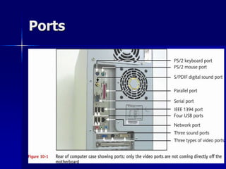
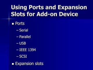
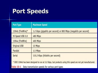
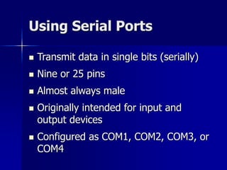
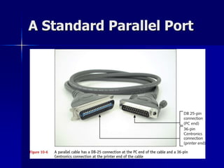
Supporting I/O Devices
Basic Principles of 
Peripheral Installations 
 Both hardware and software must be 
installed (hardware is controlled by 
software) 
 Install all levels of software 
 Device driver must be written 
specifically for the OS 
 More than one peripheral device might 
attempt to use same resources 
 Update drivers, the firmware, or both
Installation Overview 
1. Install the device (internal or external) 
2. Install the device driver 
3. Install the application software
Ports
Using Ports and Expansion 
Slots for Add-on Device 
 Ports 
– Serial 
– Parallel 
– USB 
– IEEE 1394 
– SCSI 
 Expansion slots
Port Speeds
Using Serial Ports 
 Transmit data in single bits (serially) 
 Nine or 25 pins 
 Almost always male 
 Originally intended for input and 
output devices 
 Configured as COM1, COM2, COM3, or 
COM4
Using Serial Ports 
(continued) 
 Port assignments are made in CMOS 
setup 
 Conform to standard interface called 
RS-232c 
 Data Terminal Equipment (DTE) and 
Data Communications Equipment 
(DCE) designations
Port Comparison
Default Port Assignments
Serial Port Specifications
Null Modem Connection 
 Enables data transmission between 
two DTE devices without the need for 
modems 
 Special cable (null modem cable) has 
several wires cross-connected to 
simulate modem connection
Pin Connections for a 25- 
Pin Null Modem Cable
Wire Connections on a 
25-Pin Null Modem Cable
Infrared Transceivers 
 Use resources of a serial port for 
communication 
 Create a virtual infrared serial port and 
virtual infrared port for infrared devices 
 UART logic on the motherboard controls 
serial ports on the board 
 Line-of-sight issue
Using Parallel Ports 
 Transmit data in parallel, eight bits at a 
time 
 Almost always female 
 Originally intended for printers 
 Can be configured as LPT1, LPT2, or LPT3 
 Port assignments are made in CMOS setup 
 Avoid using a cable longer than 15 feet to 
ensure data integrity
Types of Parallel Ports 
 Standard parallel port (SPP) 
– Allows data to flow in only one direction 
– Slowest of the three types 
 Enhanced Parallel Port (EPP) 
– Bi-directional 
 Extended Capabilities Port (ECP) 
– Bi-directional 
– Uses the DMA channel
A Standard Parallel Port
Configuring Parallel Ports 
 Setup can have up to four different 
settings for parallel ports
Using USB Ports 
 Effortless installation of slow peripheral 
devices 
 Much faster than regular serial ports; use 
higher-quality cabling 
 Easier to manage; eliminate need to 
manually resolve resource conflicts 
 Likely to replace serial and parallel ports
Using USB Ports (continued) 
 Allow for hot-swapping; are hot-pluggable 
 Most current motherboards have one to four 
USB ports 
 Managed by a USB host controller 
 As many as 127 USB devices can be daisy-chained 
together using USB devices
USB Ports
USB Host Controller
Requirements for 
Preparing to Install a USB 
Device 
 Motherboard or expansion card that 
provides a USB port 
 OS that supports USB 
 USB device 
 USB device driver
Installing a USB Device 
 Some devices (eg, printers) require the 
device to be plugged in before installation 
 Some devices (eg, scanners) require the 
driver to be installed before the device is 
plugged in 
 Using Device Manager, verify that USB 
controller is installed and working properly
Using IEEE 1394 Ports 
 Transmit data serially; faster than USB 
 Likely to replace SCSI for high-volume, multimedia 
external devices 
 Provide either a 4-pin or 6-pin connector 
 Hot-pluggable 
– Can be daisy-chained together and managed by a 
host controller using one set of system resources 
 Use isochronous data transfer 
Isochronous transfers involve large streams of data. This format is used to move 
continuous, real-time data streams such as voice or video. Data delivery rates are 
predetermined and correspond to the sampling rate o the device.
IEEE 1394 Port Standards 
 IEEE 1394A 
– Supports data speeds up to 1.2 Gbps 
– Allows for cable lengths up to 15 feet 
 IEEE 1394B 
– Supports speeds up to 3.2 Gbps 
– Allows for cable length up to 328 feet
IEEE 1394 Cable 
Connections
Using IEEE 1394 Ports
Keyboards 
 Traditional straight design or 
ergonomic design 
 Two technologies for keys making 
contact 
– Foil contact 
– Metal contact 
 Installing keyboards
Keyboard Connectors 
 PS/2 connector (or mini-DIN) 
– Small, round, with six pins 
 DIN (Deutsche Industrie Norm) connector 
– Round with five pins 
 USB port 
 Wireless connection 
– Requires a driver
Keyboard Connectors 
(continued)
Pinouts for Keyboard 
Connectors
Pinouts for Keyboard 
Connectors 
You'll notice a few things about the table. First, there 
are only four actual signals used in the standard 
keyboard interface; the extra pins on both types of 
connector are not used 
(This mismatch means that the connectors were 
chosen either from existing designs to save 
development costs, or that room was left for future 
expansion that was never used. Both occur commonly 
in the PC industry.)
A Keyboard Adapter 
Since the signals are the same for the two types of connector--they just use different 
pins. This means that simple mechanical adapters can be made to convert between 
the two. These adapters let a keyboard that terminates in a large connector work on a 
system that requires a small connector, and vice-versa.
Troubleshooting 
Keyboards 
 A few keys don’t work 
 Keyboard does not work at all 
 Key continues to repeat after being 
released 
 Keys produce the wrong characters 
 Major spills on the keyboard
Pointing Devices
How a Wheel Mouse 
Works
How a Mouse Connects 
to the Computer 
 Dedicated round mouse port (motherboard 
mouse or PS/2-compatible mouse) 
 Mouse bus card (bus mouse) 
 Serial port (serial mouse) 
 USB port 
 Y-connection with the keyboard 
 Cordless technology
Pointing Devices 
 Touch screens 
 Other pointing devices 
– Trackballs 
– Touch pads
Troubleshooting a Mouse 
 Check mouse port connection 
 Check for dust or dirt; reboot PC 
 Try new mouse 
 Uninstall and reinstall mouse driver; reboot PC 
 Reboot PC and select logged option from startup 
menu to create Bootlog.exe file 
– Continue to boot and check log for errors
Other Devices 
 Scanners 
 Web Cameras 
 Biometric Devices 
 Bar Code Readers 
 Touch Screens

16 supporting io devices

  • 1.
  • 2.
    Basic Principles of Peripheral Installations  Both hardware and software must be installed (hardware is controlled by software)  Install all levels of software  Device driver must be written specifically for the OS  More than one peripheral device might attempt to use same resources  Update drivers, the firmware, or both
  • 3.
    Installation Overview 1.Install the device (internal or external) 2. Install the device driver 3. Install the application software
  • 4.
  • 5.
    Using Ports andExpansion Slots for Add-on Device  Ports – Serial – Parallel – USB – IEEE 1394 – SCSI  Expansion slots
  • 6.
  • 7.
    Using Serial Ports  Transmit data in single bits (serially)  Nine or 25 pins  Almost always male  Originally intended for input and output devices  Configured as COM1, COM2, COM3, or COM4
  • 8.
    Using Serial Ports (continued)  Port assignments are made in CMOS setup  Conform to standard interface called RS-232c  Data Terminal Equipment (DTE) and Data Communications Equipment (DCE) designations
  • 9.
  • 10.
  • 11.
  • 12.
    Null Modem Connection  Enables data transmission between two DTE devices without the need for modems  Special cable (null modem cable) has several wires cross-connected to simulate modem connection
  • 13.
    Pin Connections fora 25- Pin Null Modem Cable
  • 14.
    Wire Connections ona 25-Pin Null Modem Cable
  • 15.
    Infrared Transceivers Use resources of a serial port for communication  Create a virtual infrared serial port and virtual infrared port for infrared devices  UART logic on the motherboard controls serial ports on the board  Line-of-sight issue
  • 16.
    Using Parallel Ports  Transmit data in parallel, eight bits at a time  Almost always female  Originally intended for printers  Can be configured as LPT1, LPT2, or LPT3  Port assignments are made in CMOS setup  Avoid using a cable longer than 15 feet to ensure data integrity
  • 17.
    Types of ParallelPorts  Standard parallel port (SPP) – Allows data to flow in only one direction – Slowest of the three types  Enhanced Parallel Port (EPP) – Bi-directional  Extended Capabilities Port (ECP) – Bi-directional – Uses the DMA channel
  • 18.
  • 19.
    Configuring Parallel Ports  Setup can have up to four different settings for parallel ports
  • 20.
    Using USB Ports  Effortless installation of slow peripheral devices  Much faster than regular serial ports; use higher-quality cabling  Easier to manage; eliminate need to manually resolve resource conflicts  Likely to replace serial and parallel ports
  • 21.
    Using USB Ports(continued)  Allow for hot-swapping; are hot-pluggable  Most current motherboards have one to four USB ports  Managed by a USB host controller  As many as 127 USB devices can be daisy-chained together using USB devices
  • 22.
  • 23.
  • 24.
    Requirements for Preparingto Install a USB Device  Motherboard or expansion card that provides a USB port  OS that supports USB  USB device  USB device driver
  • 25.
    Installing a USBDevice  Some devices (eg, printers) require the device to be plugged in before installation  Some devices (eg, scanners) require the driver to be installed before the device is plugged in  Using Device Manager, verify that USB controller is installed and working properly
  • 26.
    Using IEEE 1394Ports  Transmit data serially; faster than USB  Likely to replace SCSI for high-volume, multimedia external devices  Provide either a 4-pin or 6-pin connector  Hot-pluggable – Can be daisy-chained together and managed by a host controller using one set of system resources  Use isochronous data transfer Isochronous transfers involve large streams of data. This format is used to move continuous, real-time data streams such as voice or video. Data delivery rates are predetermined and correspond to the sampling rate o the device.
  • 27.
    IEEE 1394 PortStandards  IEEE 1394A – Supports data speeds up to 1.2 Gbps – Allows for cable lengths up to 15 feet  IEEE 1394B – Supports speeds up to 3.2 Gbps – Allows for cable length up to 328 feet
  • 28.
    IEEE 1394 Cable Connections
  • 29.
  • 30.
    Keyboards  Traditionalstraight design or ergonomic design  Two technologies for keys making contact – Foil contact – Metal contact  Installing keyboards
  • 31.
    Keyboard Connectors PS/2 connector (or mini-DIN) – Small, round, with six pins  DIN (Deutsche Industrie Norm) connector – Round with five pins  USB port  Wireless connection – Requires a driver
  • 32.
  • 33.
  • 34.
    Pinouts for Keyboard Connectors You'll notice a few things about the table. First, there are only four actual signals used in the standard keyboard interface; the extra pins on both types of connector are not used (This mismatch means that the connectors were chosen either from existing designs to save development costs, or that room was left for future expansion that was never used. Both occur commonly in the PC industry.)
  • 35.
    A Keyboard Adapter Since the signals are the same for the two types of connector--they just use different pins. This means that simple mechanical adapters can be made to convert between the two. These adapters let a keyboard that terminates in a large connector work on a system that requires a small connector, and vice-versa.
  • 36.
    Troubleshooting Keyboards A few keys don’t work  Keyboard does not work at all  Key continues to repeat after being released  Keys produce the wrong characters  Major spills on the keyboard
  • 37.
  • 38.
    How a WheelMouse Works
  • 39.
    How a MouseConnects to the Computer  Dedicated round mouse port (motherboard mouse or PS/2-compatible mouse)  Mouse bus card (bus mouse)  Serial port (serial mouse)  USB port  Y-connection with the keyboard  Cordless technology
  • 40.
    Pointing Devices Touch screens  Other pointing devices – Trackballs – Touch pads
  • 41.
    Troubleshooting a Mouse  Check mouse port connection  Check for dust or dirt; reboot PC  Try new mouse  Uninstall and reinstall mouse driver; reboot PC  Reboot PC and select logged option from startup menu to create Bootlog.exe file – Continue to boot and check log for errors
  • 42.
    Other Devices Scanners  Web Cameras  Biometric Devices  Bar Code Readers  Touch Screens