Downloaded 251 times

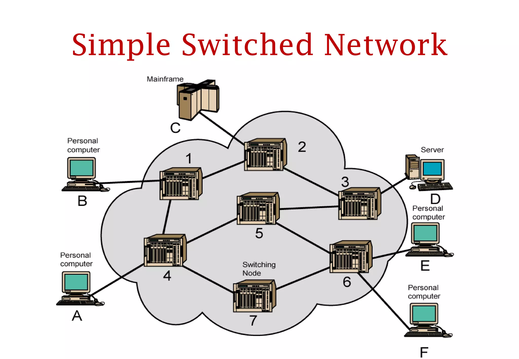
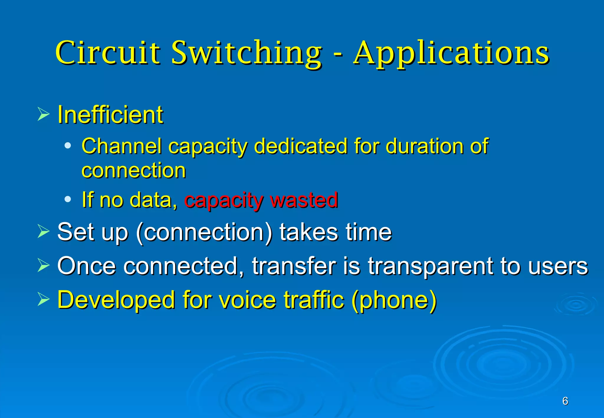
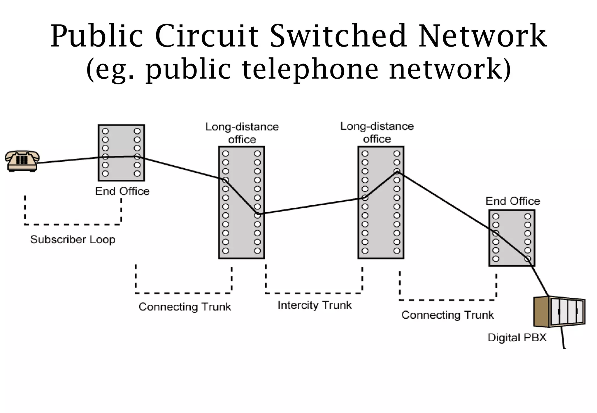
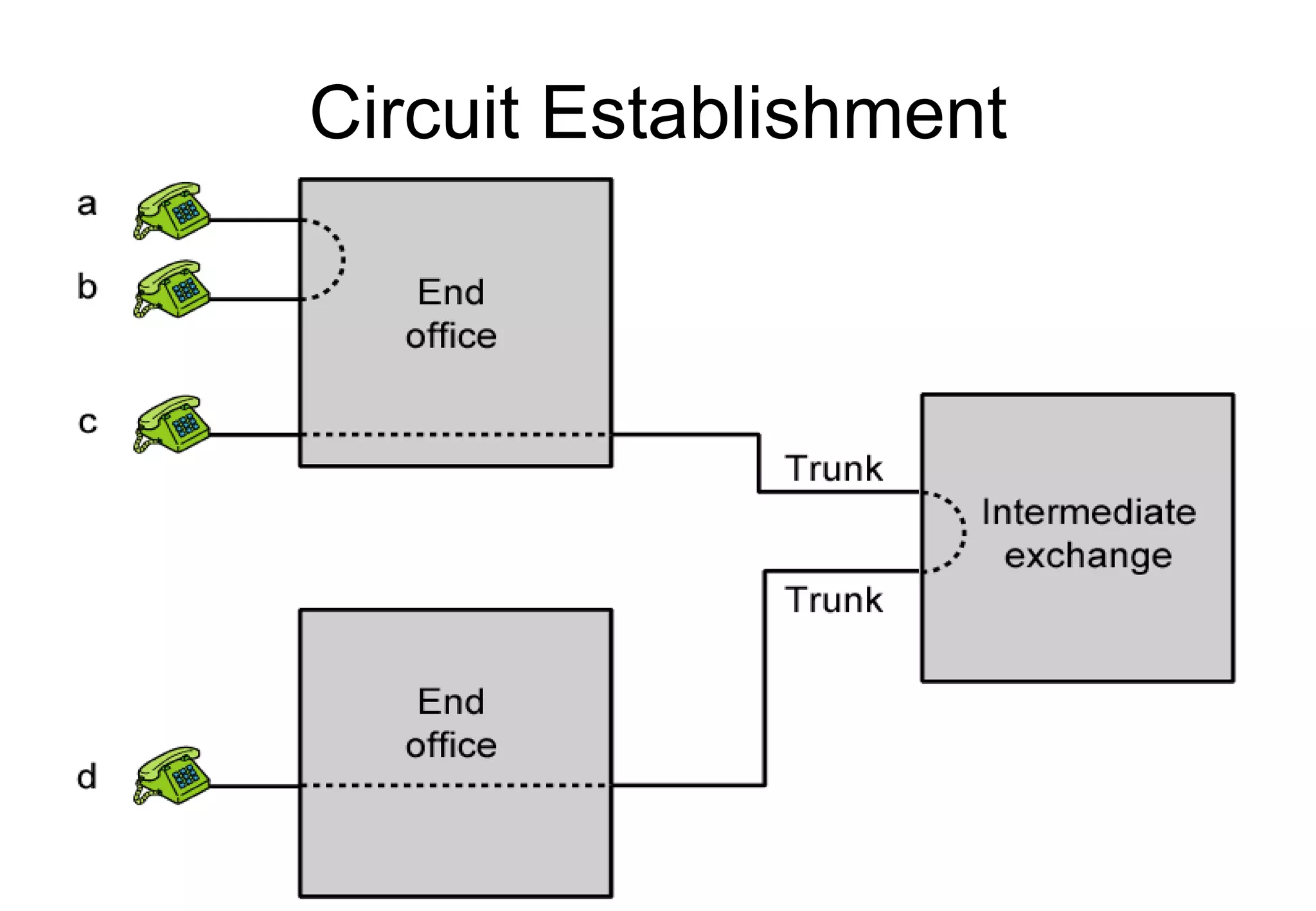
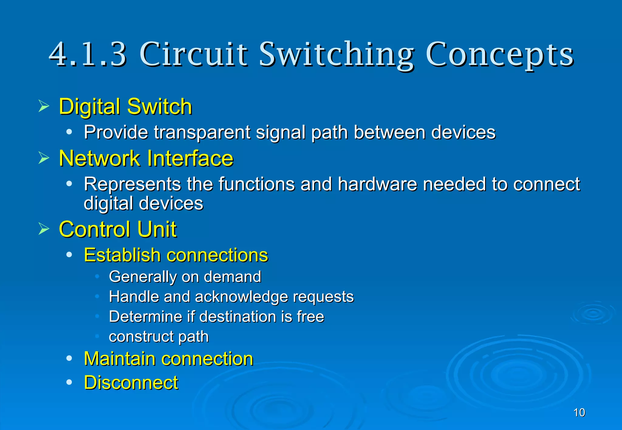
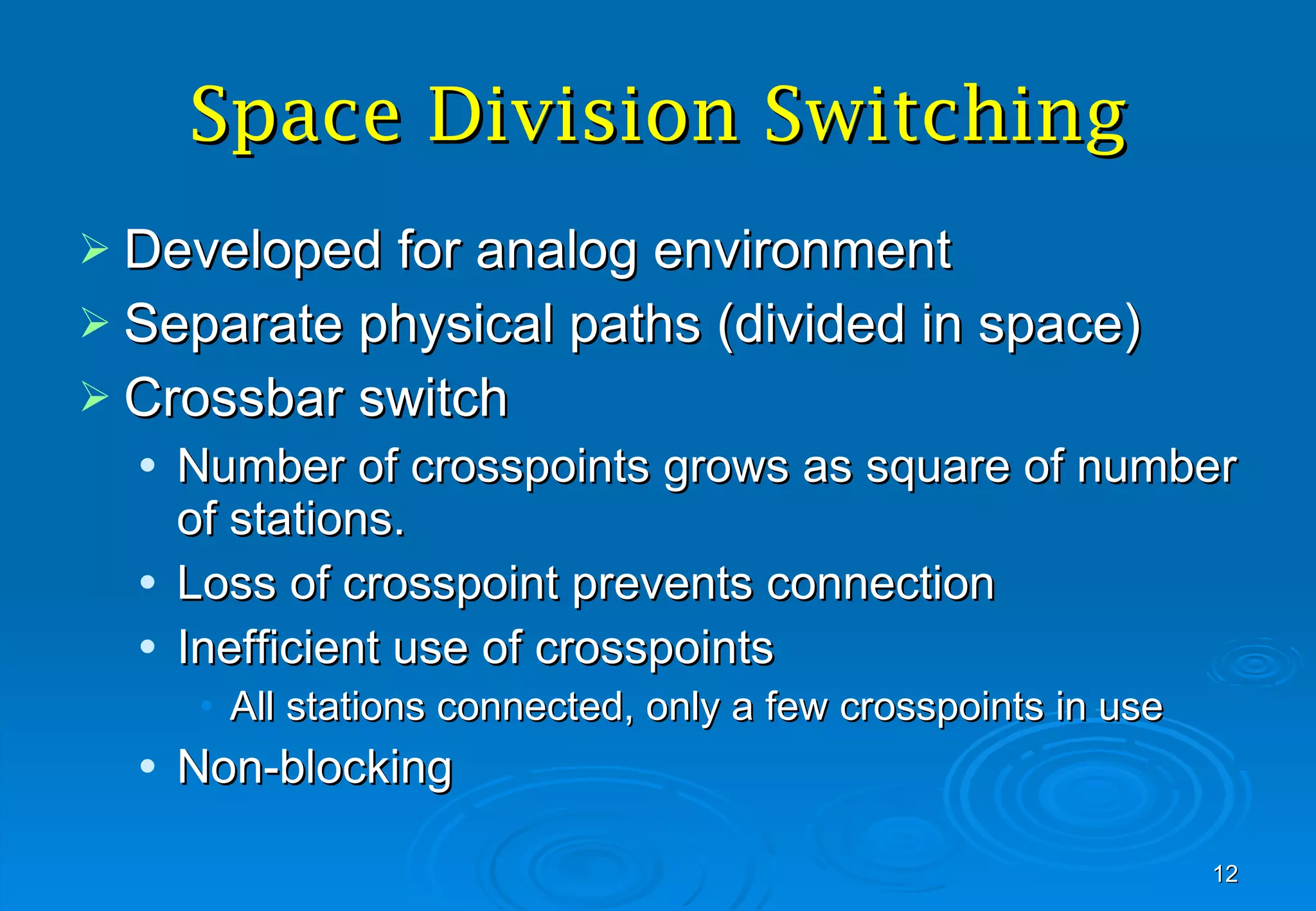
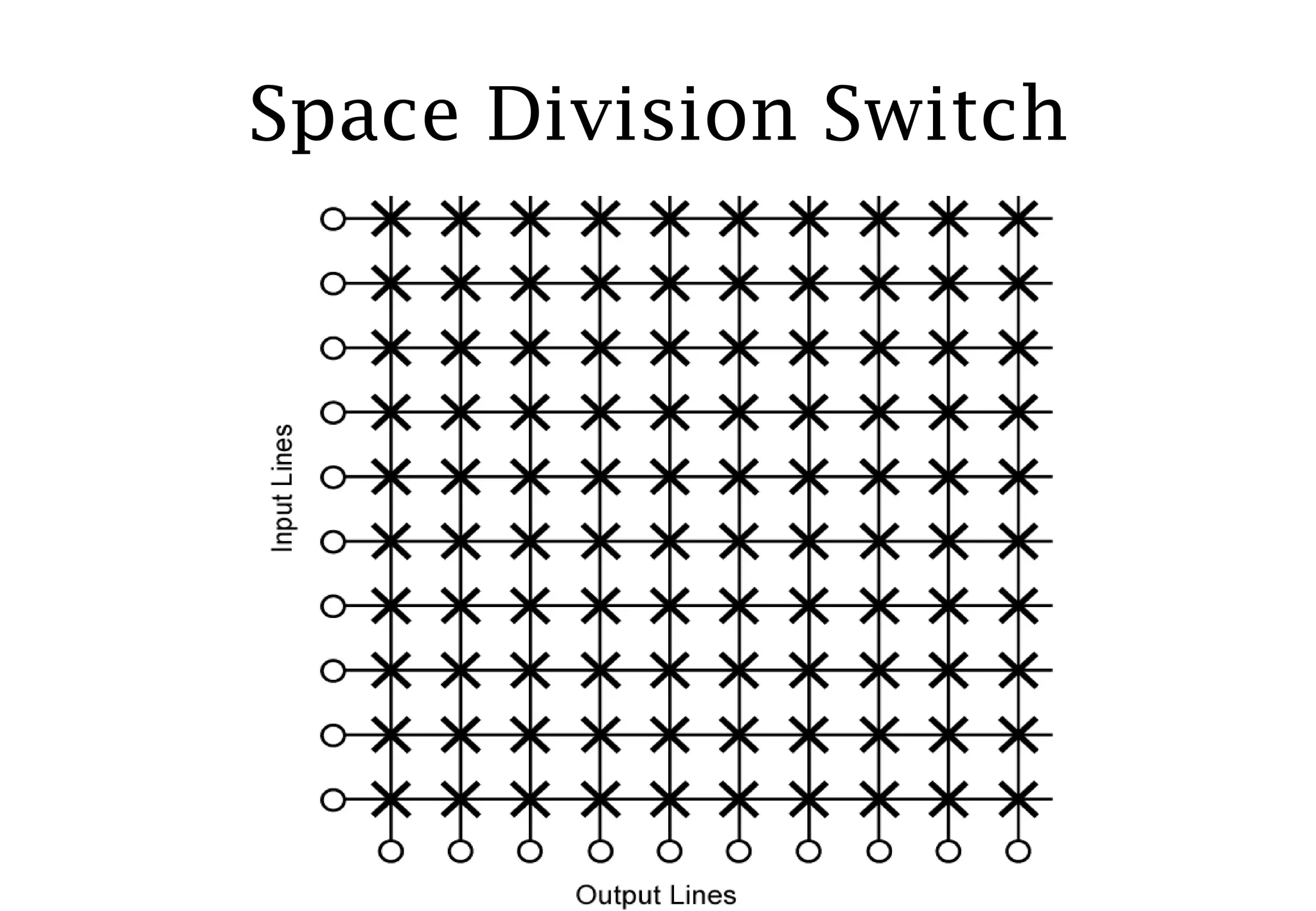
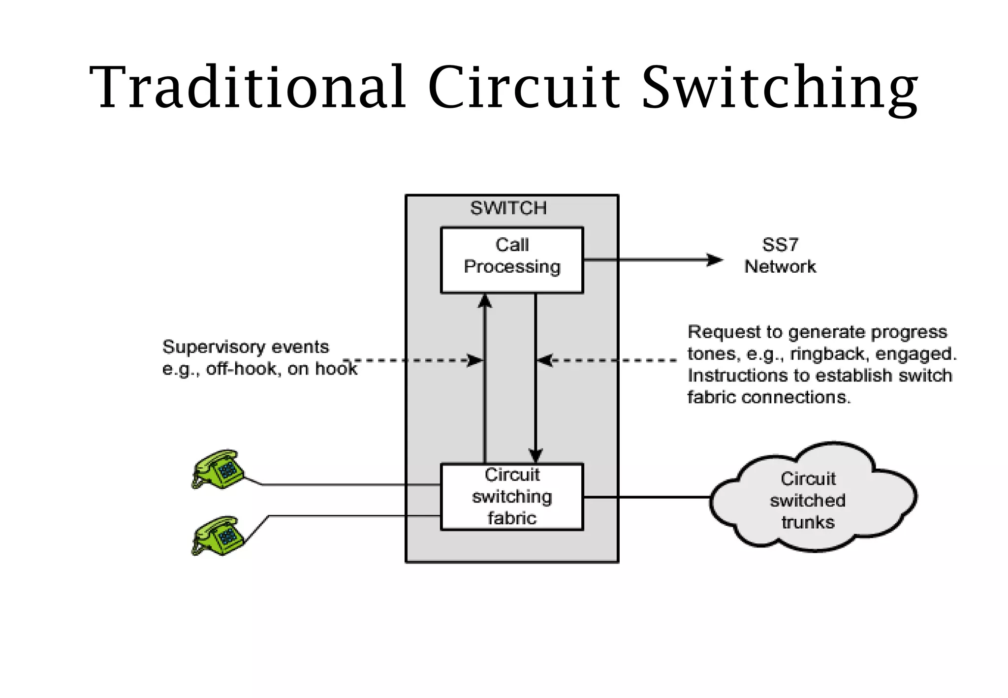
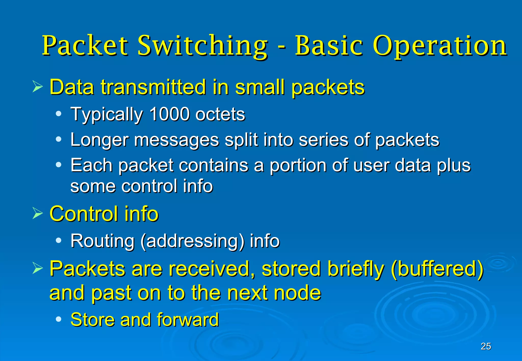
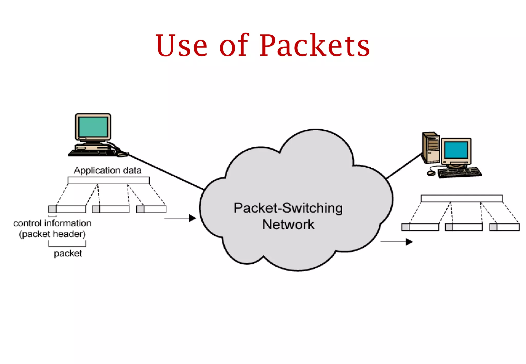
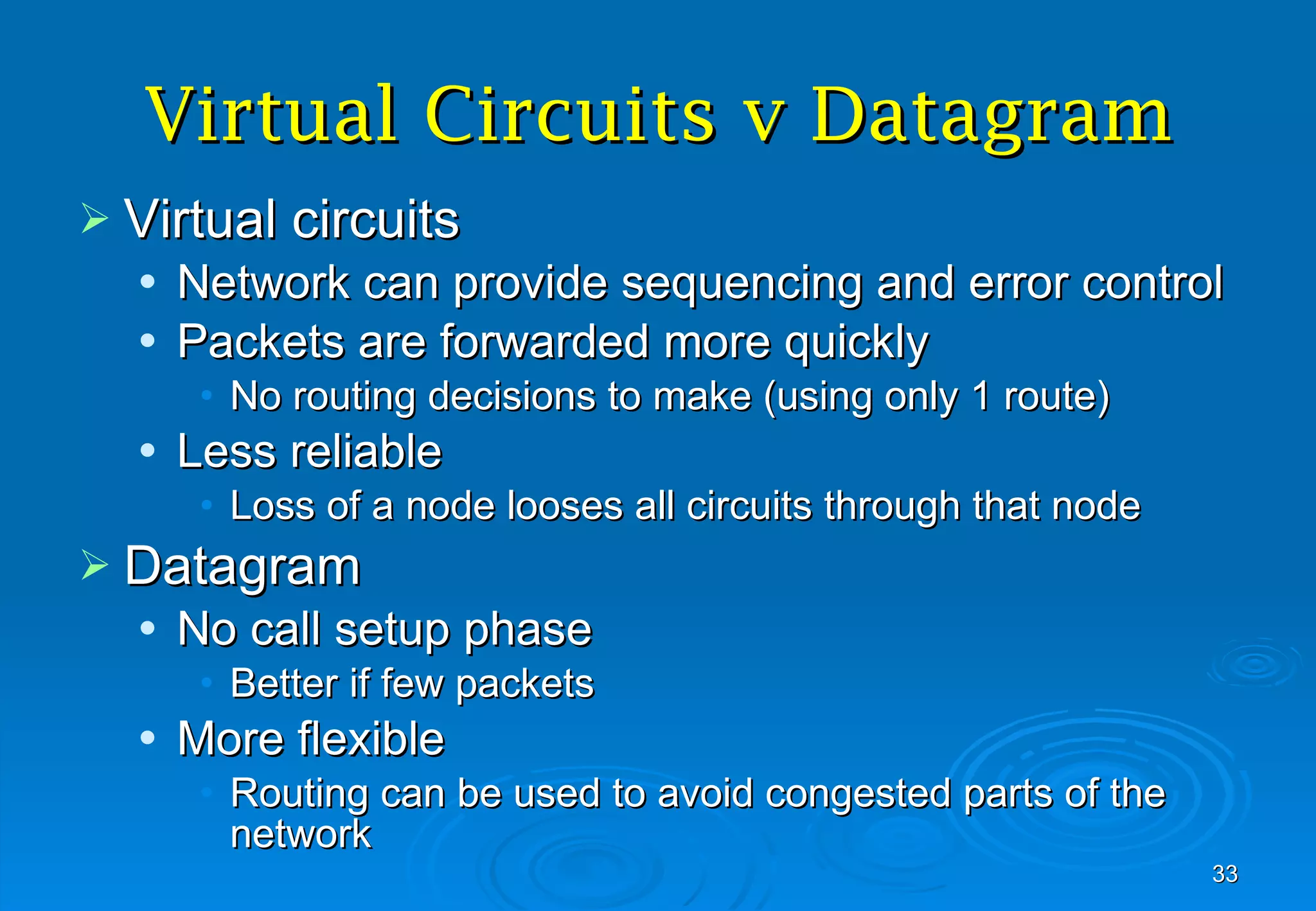

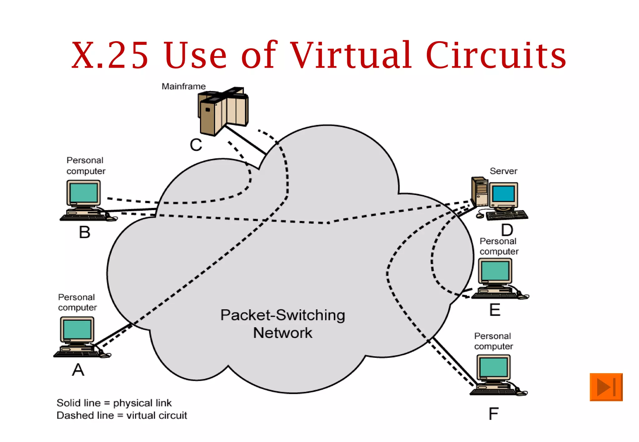
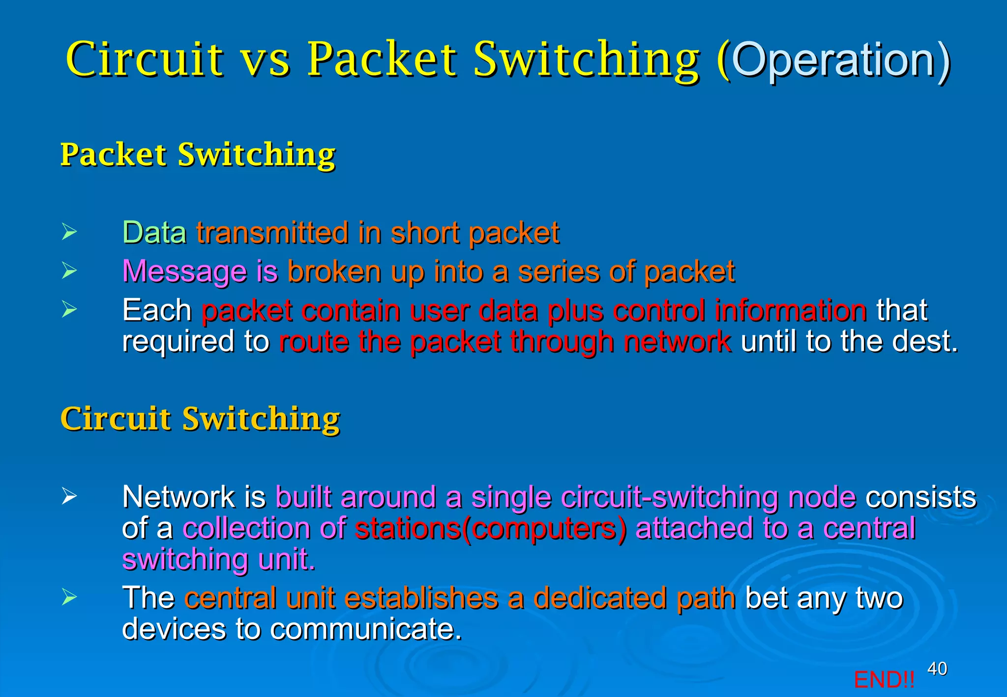

Circuit switching and packet switching are two methods for transferring data across networks. Circuit switching establishes a dedicated communication path between two stations by reserving bandwidth for the duration of the call. Packet switching breaks messages into packets that are transmitted independently across the network and reassembled at the destination. It allows for more efficient use of bandwidth by allowing packets from multiple messages to share transmission resources.


![2[1].1 data transmission](https://cdn.slidesharecdn.com/ss_thumbnails/21-1-datatransmission-111203164944-phpapp01-thumbnail.jpg?width=640&height=640&fit=bounds)


