Switched Network
• Anetwork is a set of connected devices.
• Whenever we have multiple devices, we have the
problem of how to connect them to make one-to-one
communication possible.
• One solution is to make a point-to-point connection
between each pair of devices (mesh or star topology).
— impractical and wasteful when applied to very large
networks.
• Multipoint connection –bus topology
- ruled out because the distances between devices and the total
number of devices increases beyond the capacities of the
3.
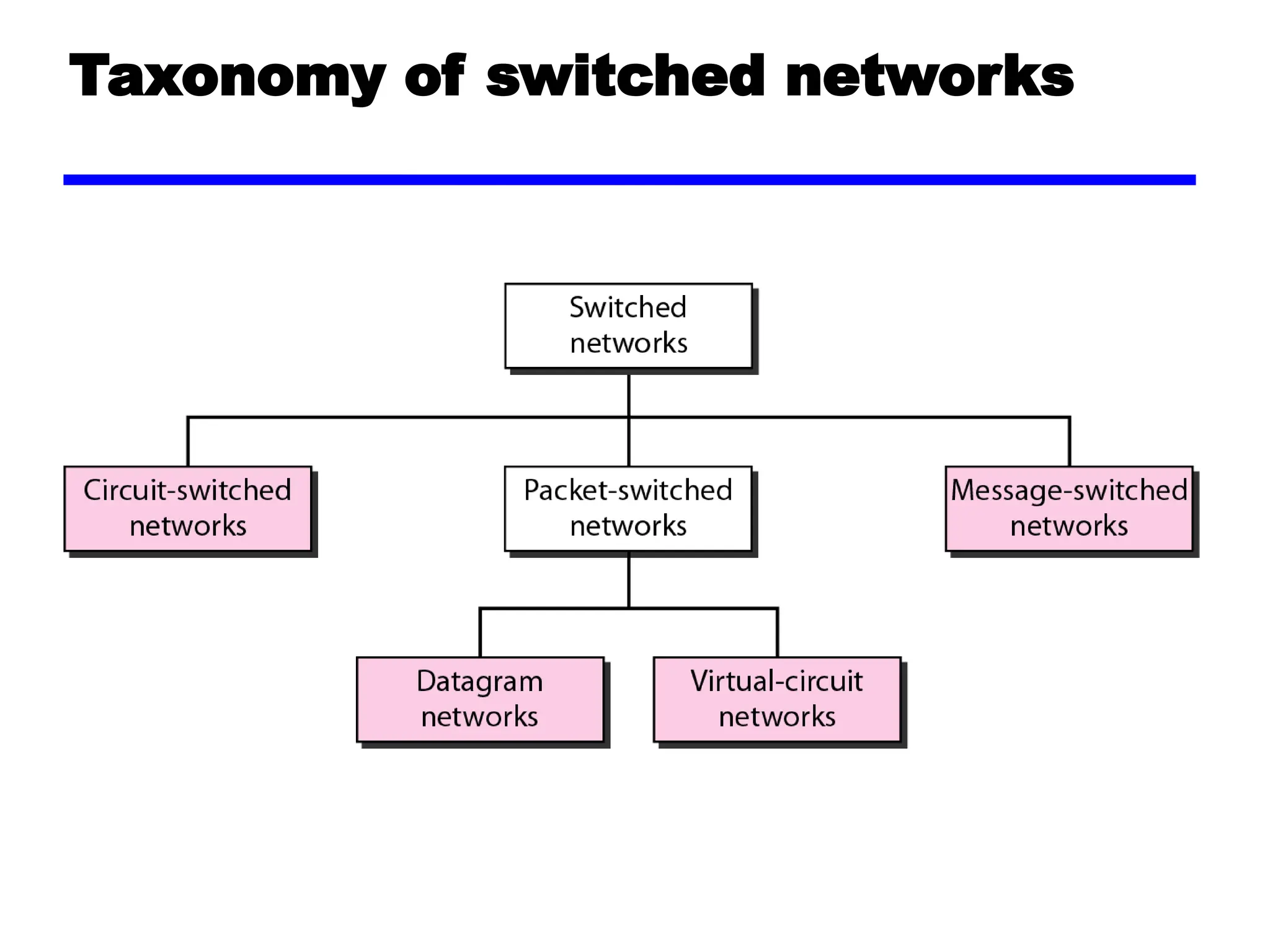
• A bettersolution is switching. A switched network
consists of a series of interlinked nodes, called
switches.
• Switches are devices capable of creating temporary
connections between two or more devices linked to
the switch.
• In a switched network, some of these nodes are
connected to the end systems (computers or
telephones, for example). Others are used only for
routing.
4.
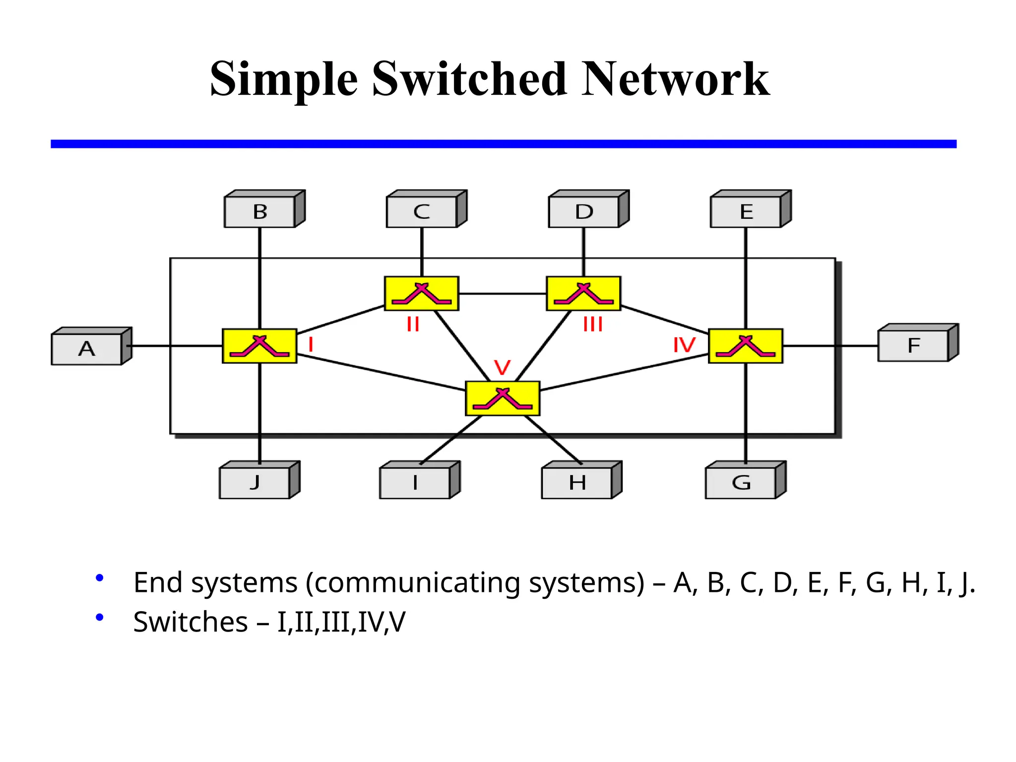
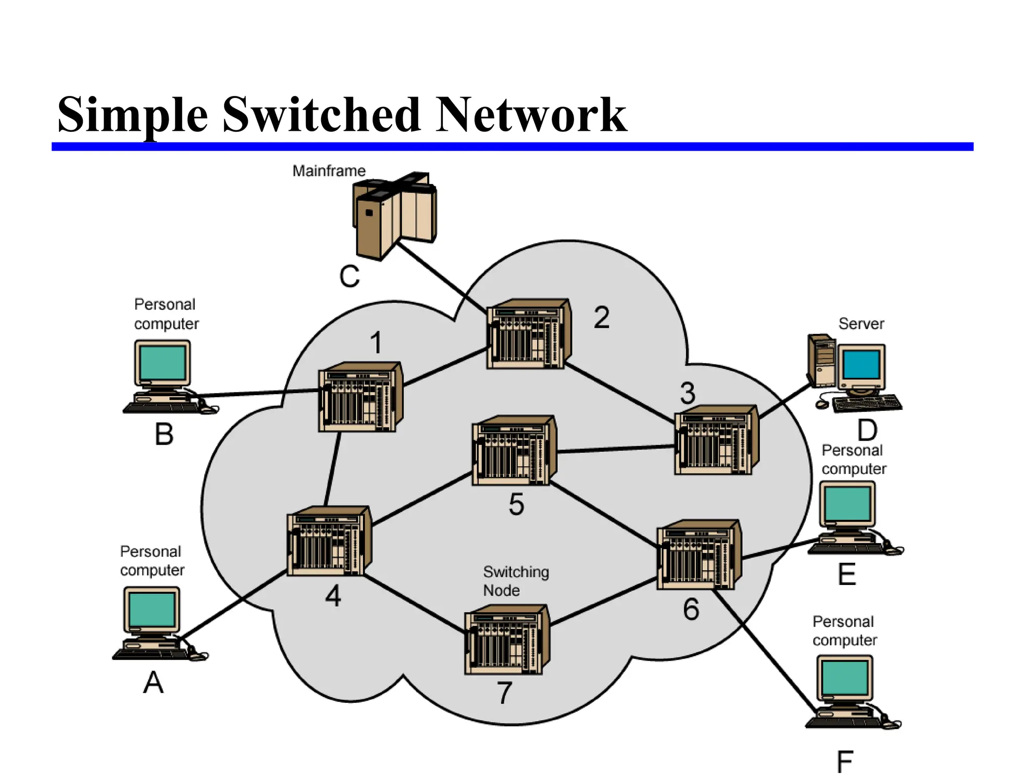
Simple Switched Network
•End systems (communicating systems) – A, B, C, D, E, F, G, H, I, J.
• Switches – I,II,III,IV,V
Switching Networks
• Longdistance transmission is typically done over a
network of switched nodes
• Nodes not concerned with content of data
• End devices are stations
—Computer, terminal, phone, etc.
• A collection of nodes and connections is a
communications network
• Data routed being switched from node to node
7.
Nodes
• Nodes mayconnect to other nodes only, or to stations
and other nodes
• Node to node links usually multiplexed
• Network is usually partially connected
—Some redundant connections are desirable for reliability
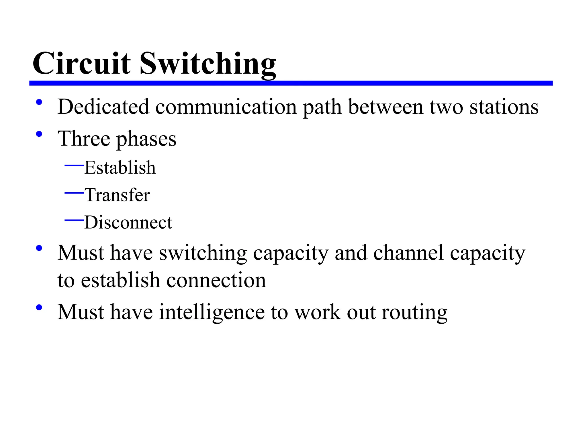
Circuit Switching
• Dedicatedcommunication path between two stations
• Three phases
—Establish
—Transfer
—Disconnect
• Must have switching capacity and channel capacity
to establish connection
• Must have intelligence to work out routing
10.
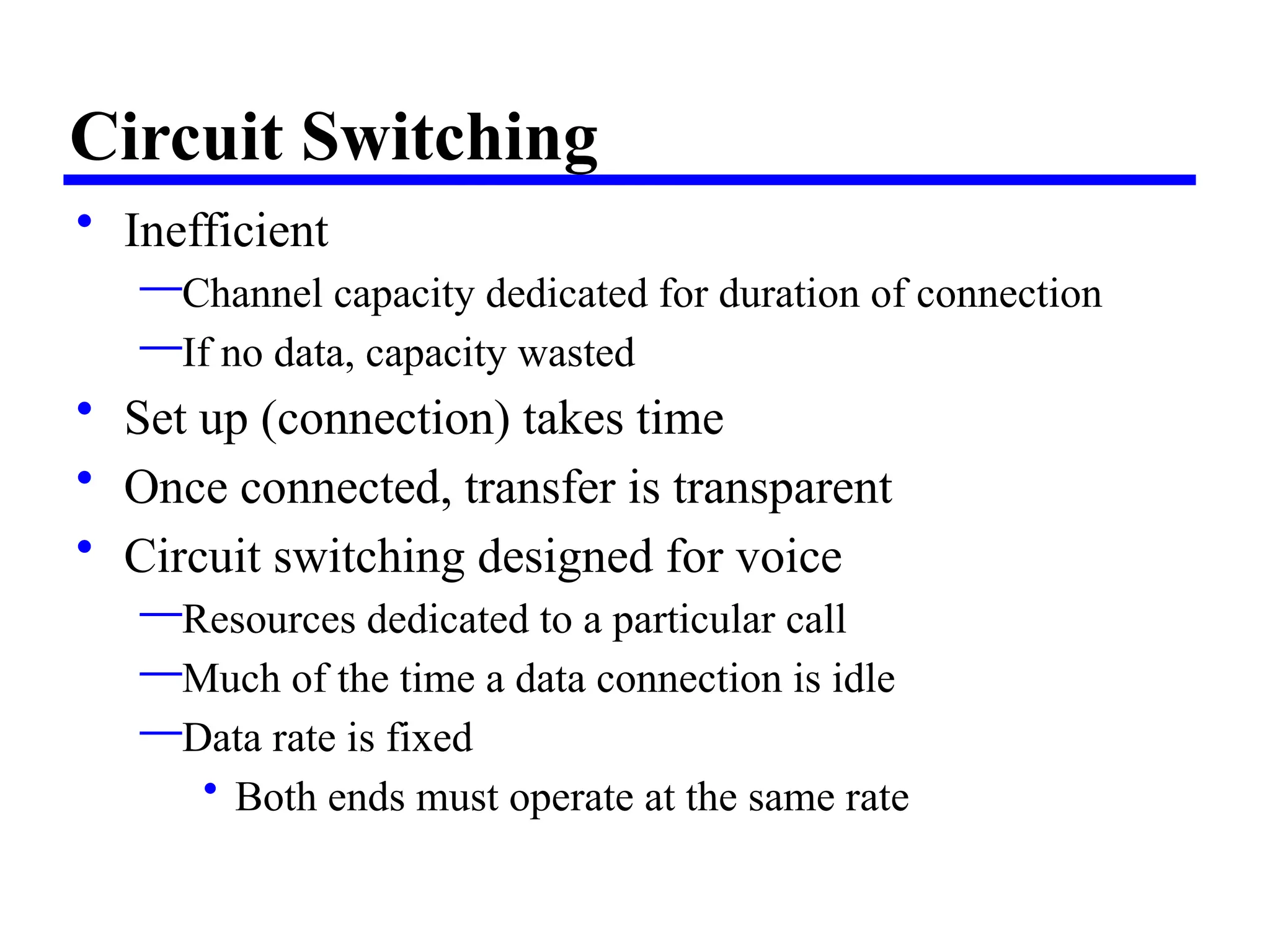
Circuit Switching
• Inefficient
—Channelcapacity dedicated for duration of connection
—If no data, capacity wasted
• Set up (connection) takes time
• Once connected, transfer is transparent
• Circuit switching designed for voice
—Resources dedicated to a particular call
—Much of the time a data connection is idle
—Data rate is fixed
• Both ends must operate at the same rate
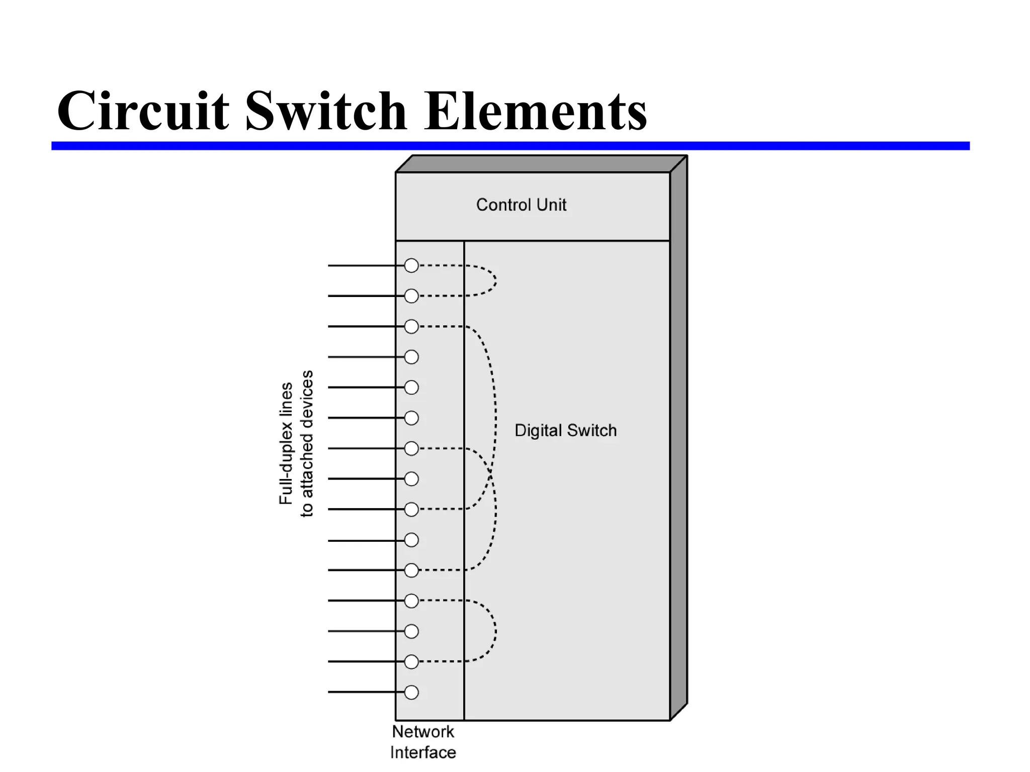
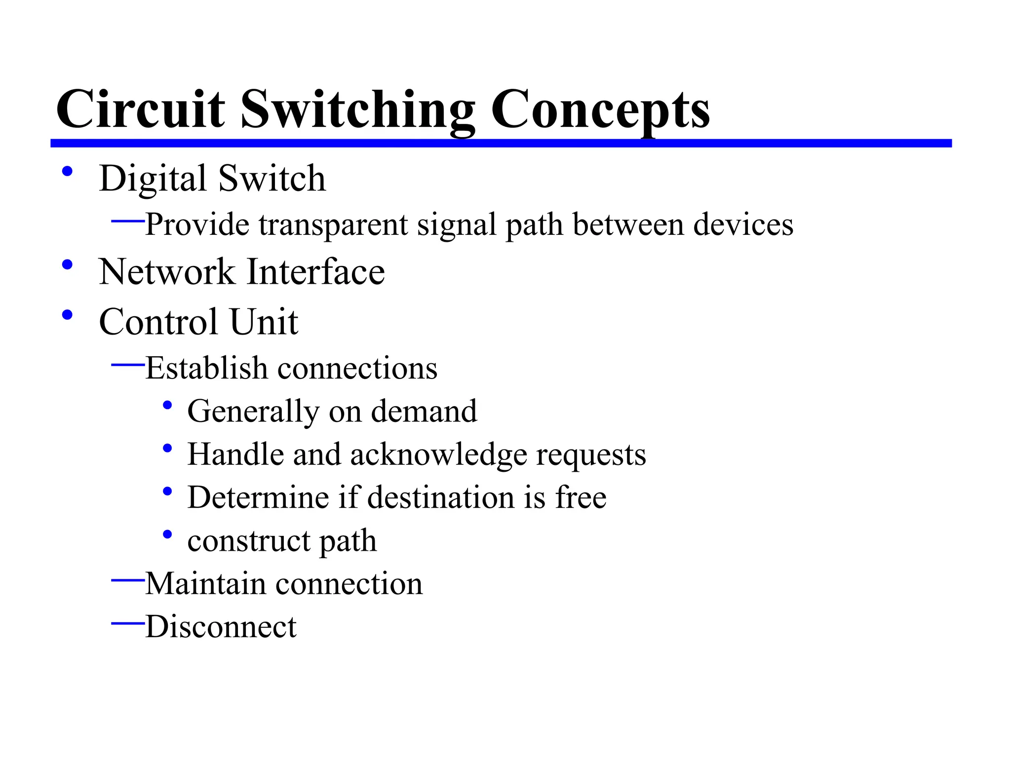
Circuit Switching Concepts
•Digital Switch
—Provide transparent signal path between devices
• Network Interface
• Control Unit
—Establish connections
• Generally on demand
• Handle and acknowledge requests
• Determine if destination is free
• construct path
—Maintain connection
—Disconnect
15.
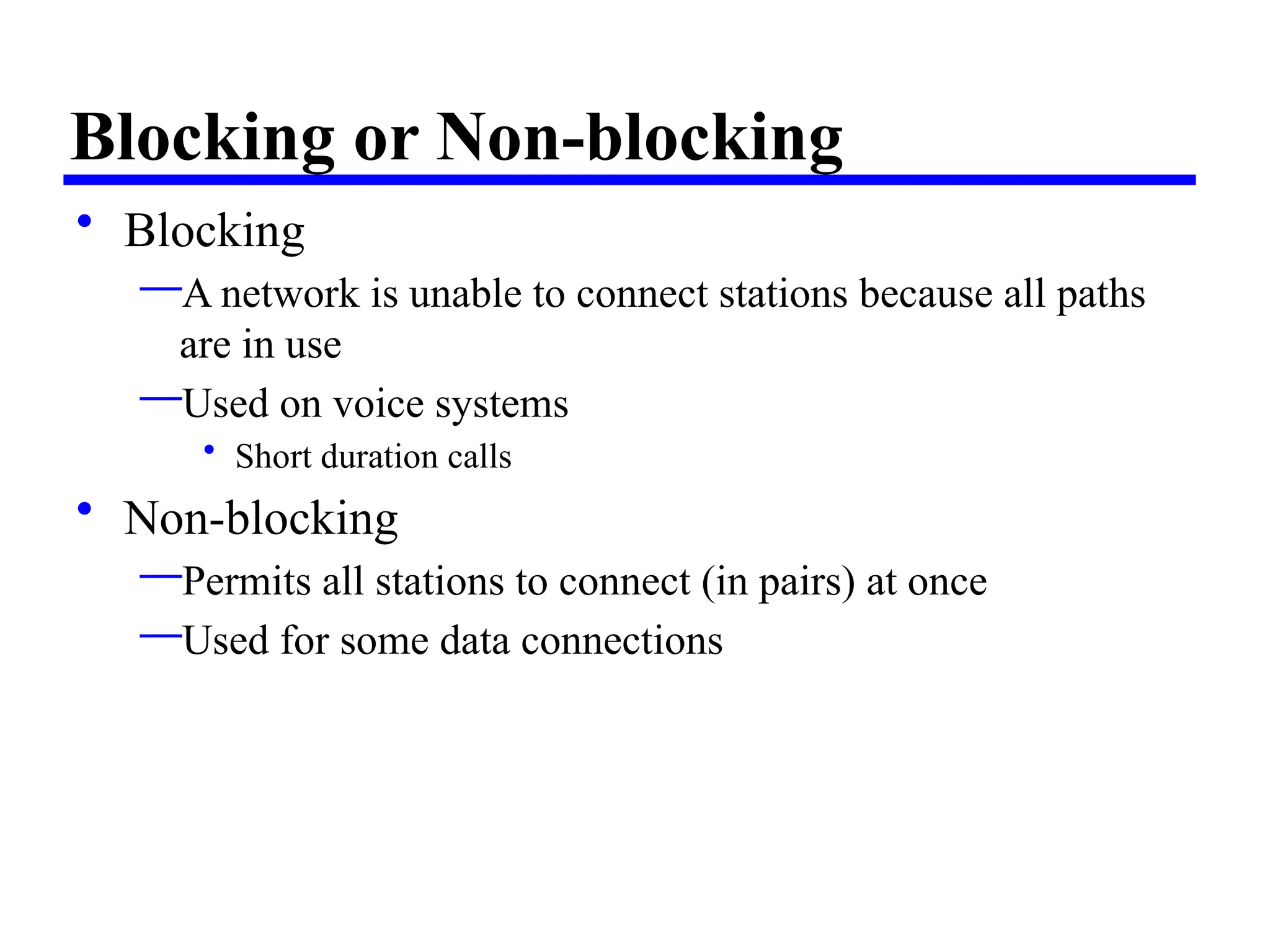
Blocking or Non-blocking
•Blocking
—A network is unable to connect stations because all paths
are in use
—Used on voice systems
• Short duration calls
• Non-blocking
—Permits all stations to connect (in pairs) at once
—Used for some data connections
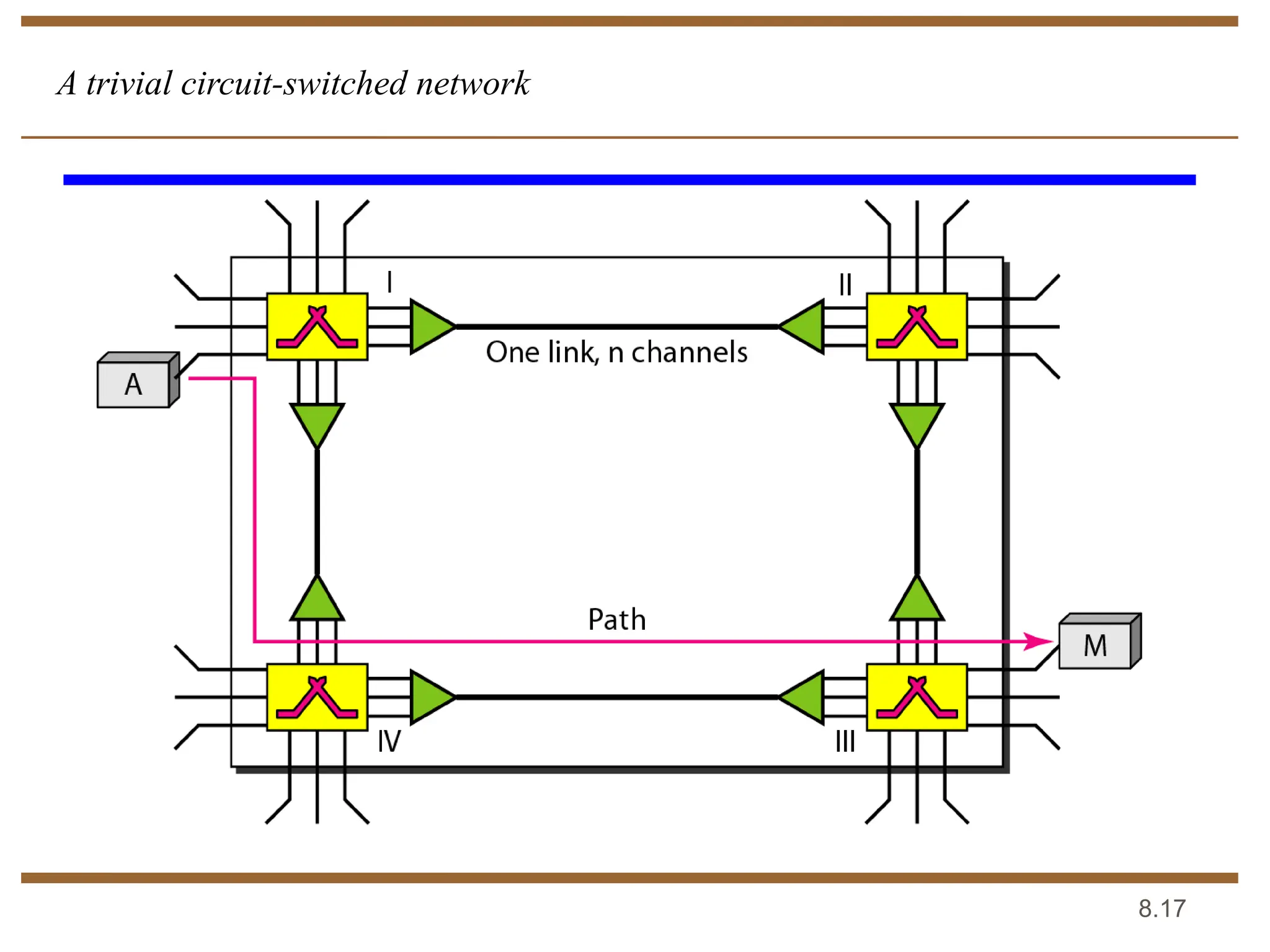
8.18
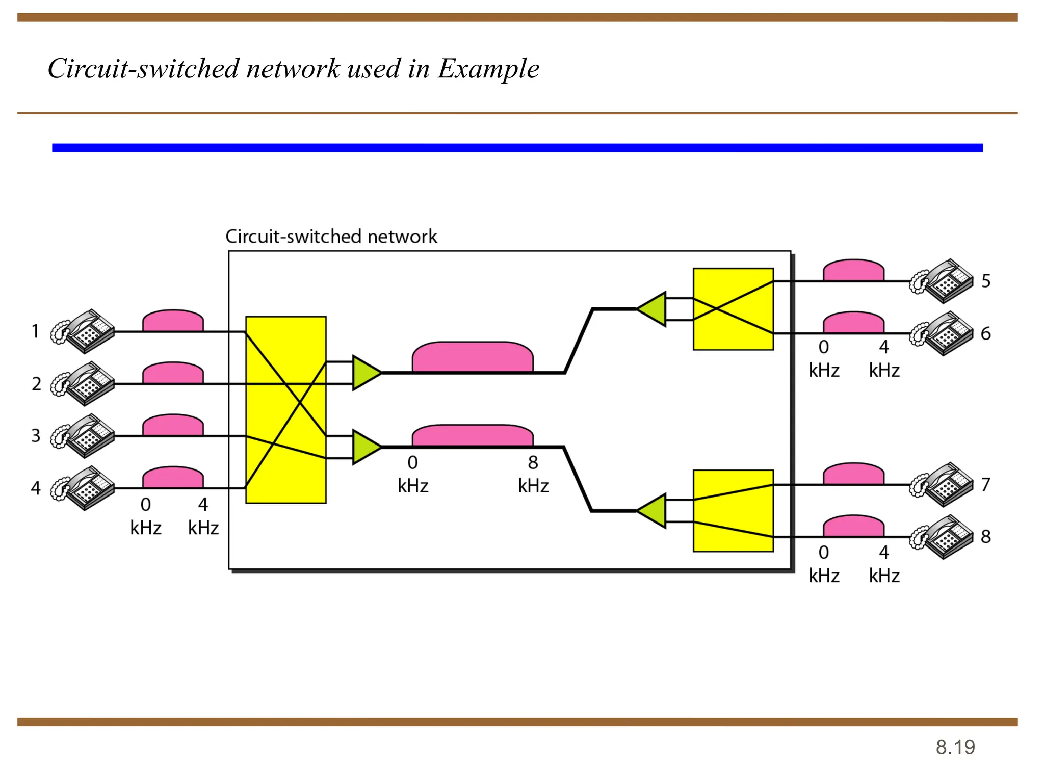
As a trivialexample, let us use a circuit-switched network
to connect eight telephones in a small area.
Communication is through 4-kHz voice channels. We
assume that each link uses FDM to connect a maximum of
two voice channels. The bandwidth of each link is then 8
kHz. Figure 8.4 shows the situation. Telephone 1 is
connected to telephone 7; 2 to 5; 3 to 8; and 4 to 6. Of
course the situation may change when new connections are
made. The switch controls the connections.
Example
Packet Switching Principles
•In a packet-switched network, there is no resource
reservation; resources are allocated on demand.
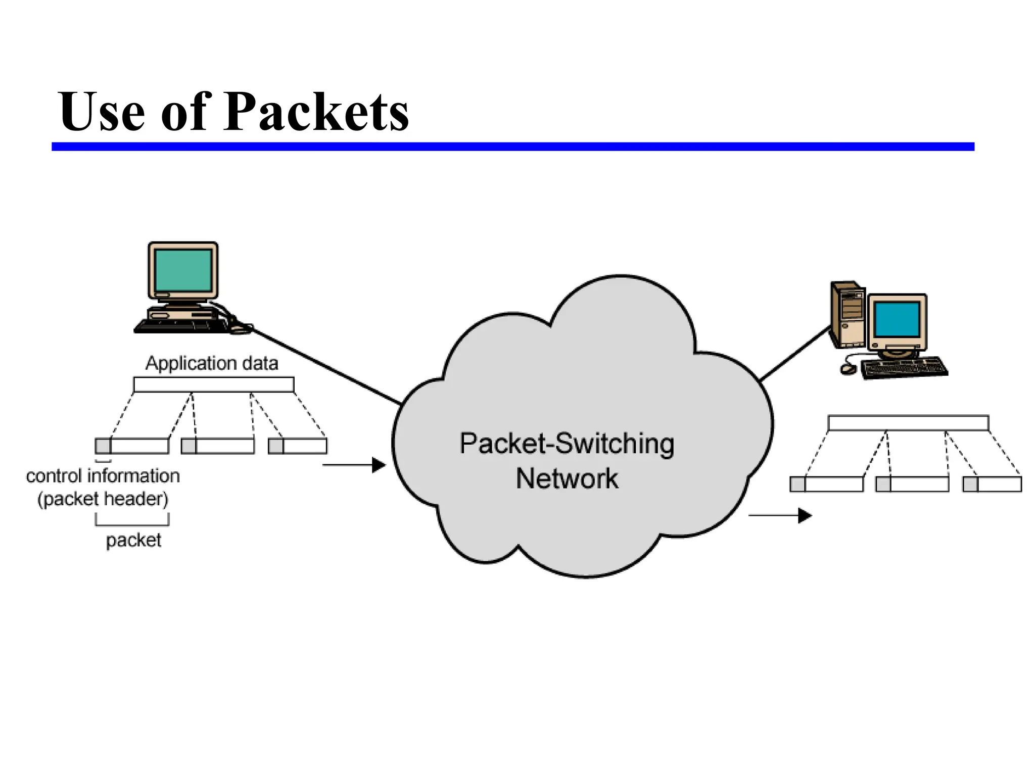
• Data transmitted in small packets
—Typically 1000 octets
—Longer messages split into series of packets
—Each packet contains a portion of user data plus some
control info
• Control info
—Routing (addressing) info
• Packets are received, stored briefly (buffered) and
past on to the next node
Advantages
• Line efficiency
—Singlenode to node link can be shared by many packets
over time
—Packets queued and transmitted as fast as possible
• Data rate conversion
—Each station connects to the local node at its own speed
—Nodes buffer data if required to equalize rates
• Packets are accepted even when network is busy
—Delivery may slow down
• Priorities can be used
22.
Packet Switching Technique
•Station breaks long message into packets
• Packets sent one at a time to the network
• Packets handled in two ways
—Datagram Approach
—Virtual circuit Approach
23.
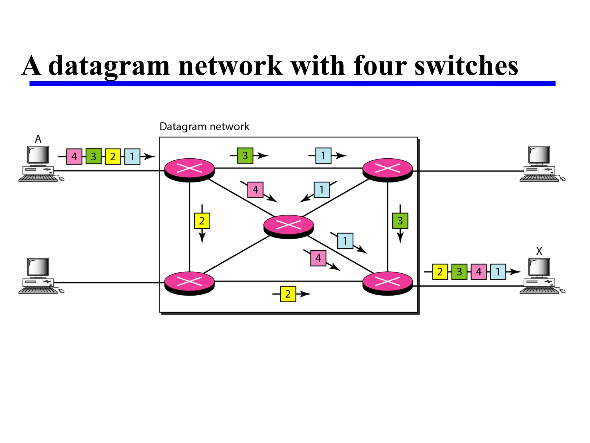
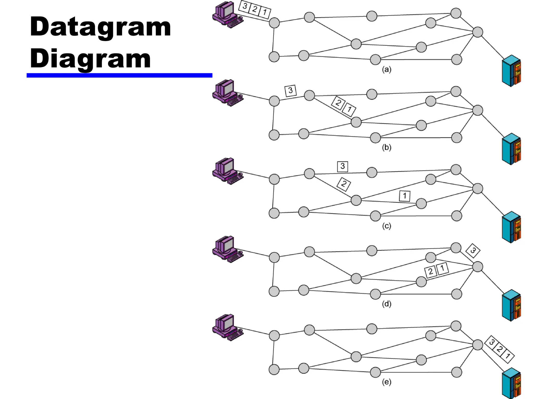
Datagram Approach
• Eachpacket treated independently
• Packets can take any practical route
• Packets may arrive out of order
• Packets may go missing
• Up to receiver to re-order packets and recover from
missing packets.
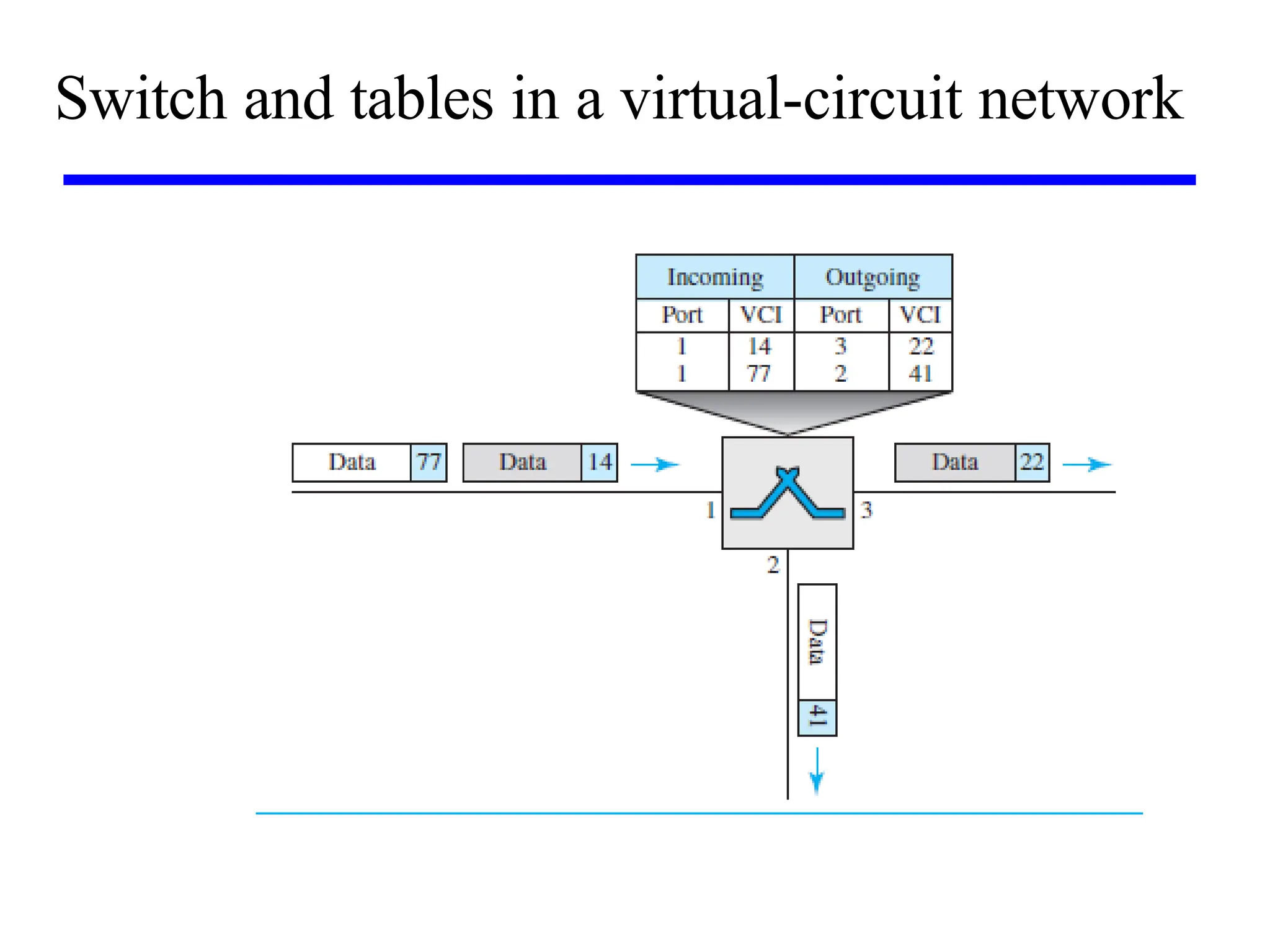
• A switch in a datagram network uses a routing table
that is based on the destination address.
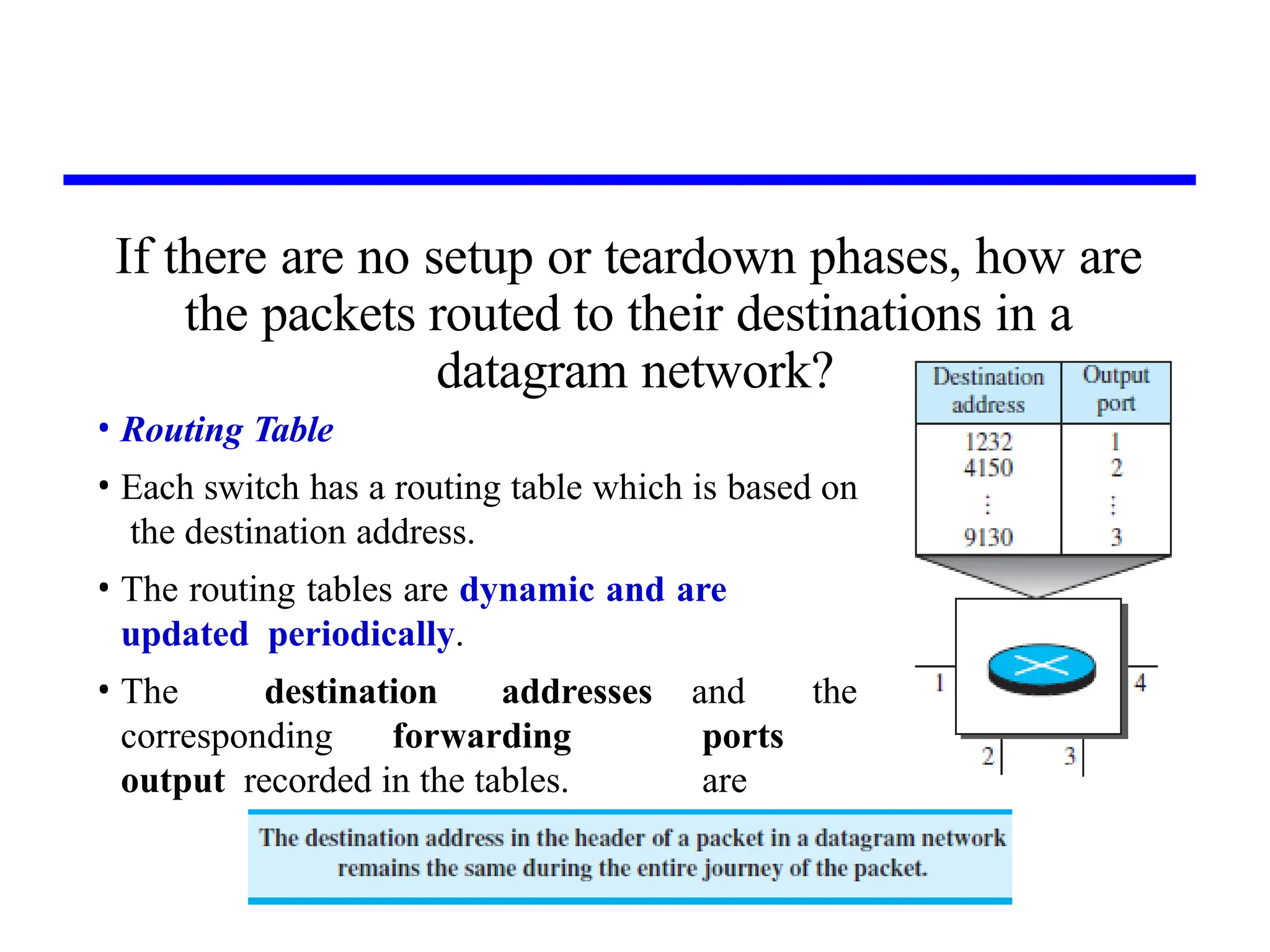
If there areno setup or teardown phases, how are
the packets routed to their destinations in a
datagram network?
• Routing Table
• Each switch has a routing table which is based on
the destination address.
• The routing tables are dynamic and are
updated periodically.
• The destination addresses
corresponding forwarding
output recorded in the tables.
and the
ports
are
27.
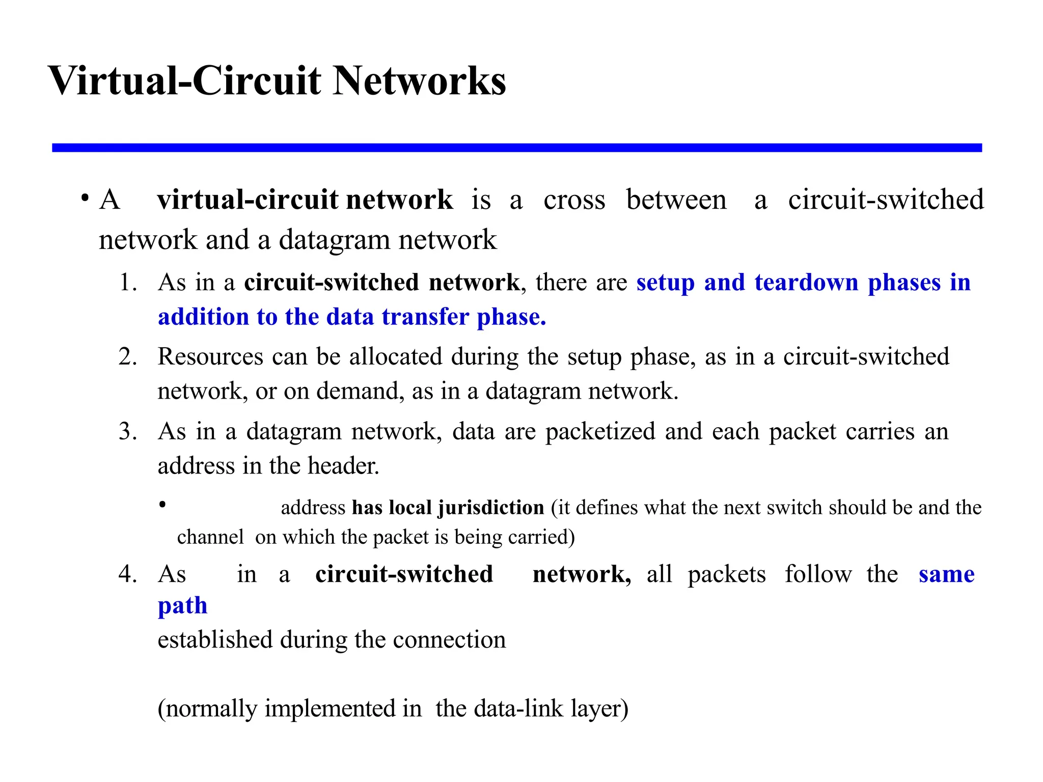
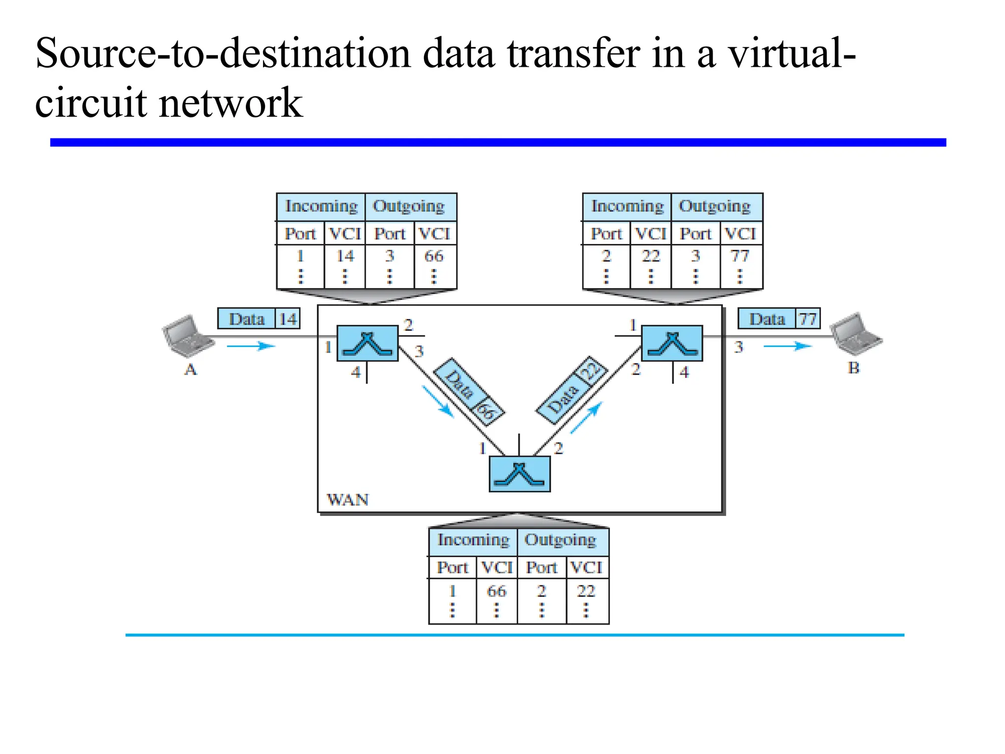
Virtual-Circuit Networks
• Avirtual-circuit network is a cross between a circuit-switched
network and a datagram network
1. As in a circuit-switched network, there are setup and teardown phases in
addition to the data transfer phase.
2. Resources can be allocated during the setup phase, as in a circuit-switched
network, or on demand, as in a datagram network.
3. As in a datagram network, data are packetized and each packet carries an
address in the header.
• address has local jurisdiction (it defines what the next switch should be and the
channel on which the packet is being carried)
4. As in a circuit-switched network, all packets follow the same
path
established during the connection
(normally implemented in the data-link layer)
28.
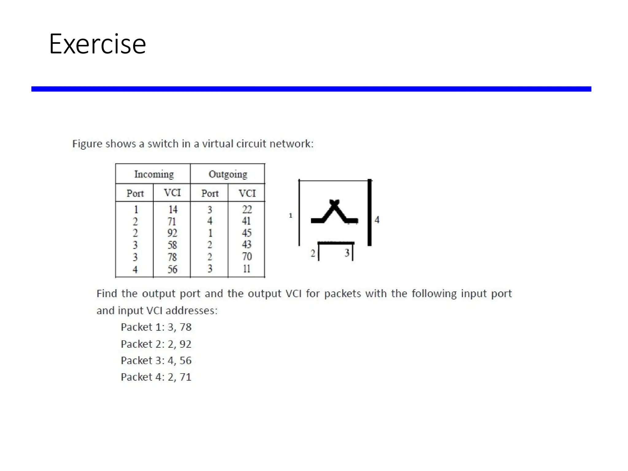
Addressing in Virtualcircuit Networks
• Global -A source or a destination needs to have a global address— an
address that can be unique in the scope of the network
• Local (virtual-circuit identifier) or label-used for data transfer is a
small number that has only switch scope; it is used by a frame
between two switches
• Each switch can use its own unique set of VCIs.
29.
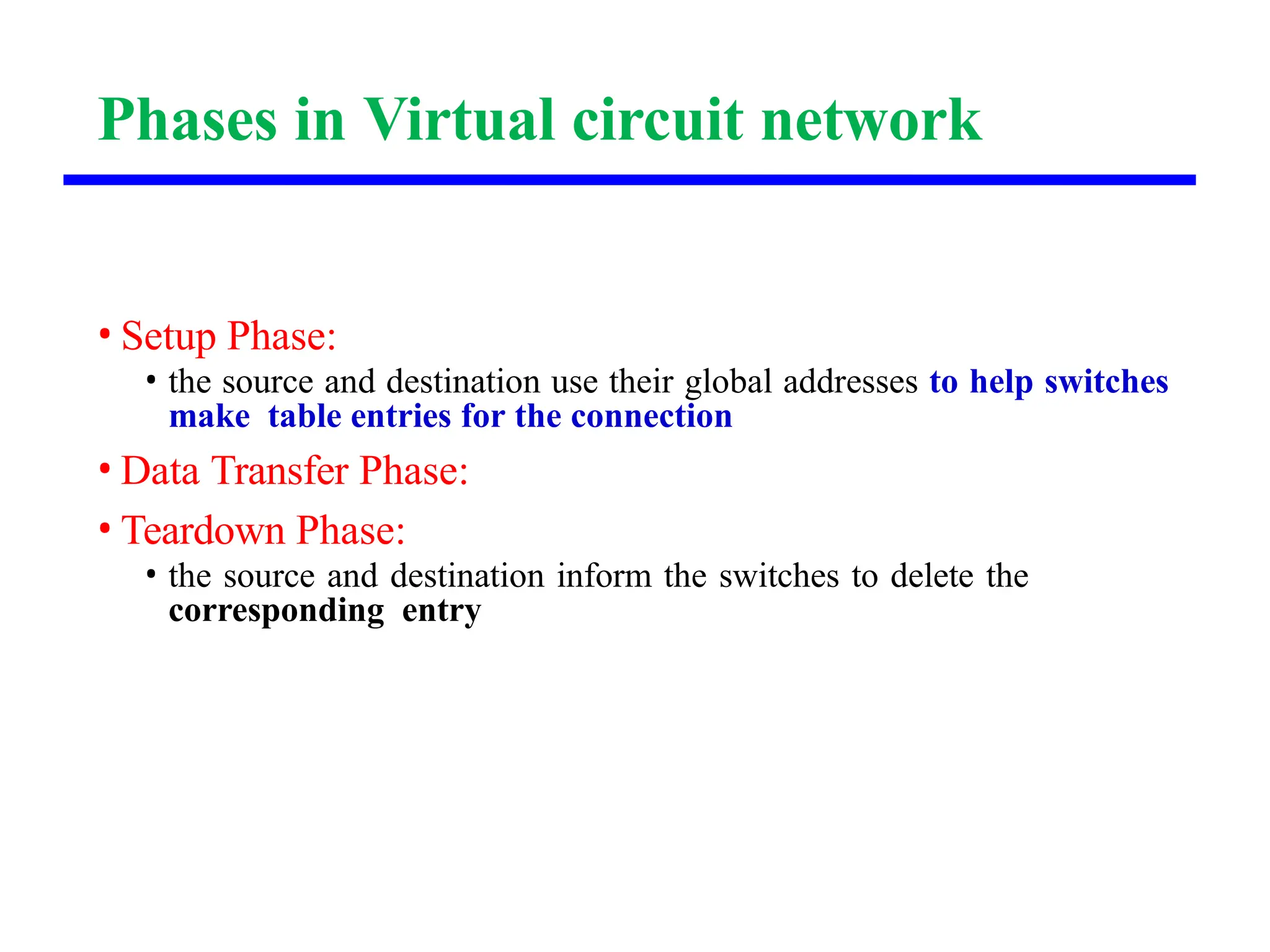
Phases in Virtualcircuit network
• Setup Phase:
• the source and destination use their global addresses to help switches
make table entries for the connection
• Data Transfer Phase:
• Teardown Phase:
• the source and destination inform the switches to delete the
corresponding entry
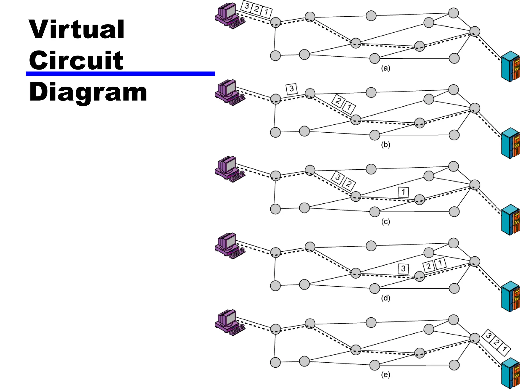
Virtual Circuit Approach
•Preplanned route established before any packets sent
• Call request and call accept packets establish
connection (handshake)
• Each packet contains a virtual circuit identifier
instead of destination address
• No routing decisions required for each packet
• Clear request to drop circuit
• Not a dedicated path
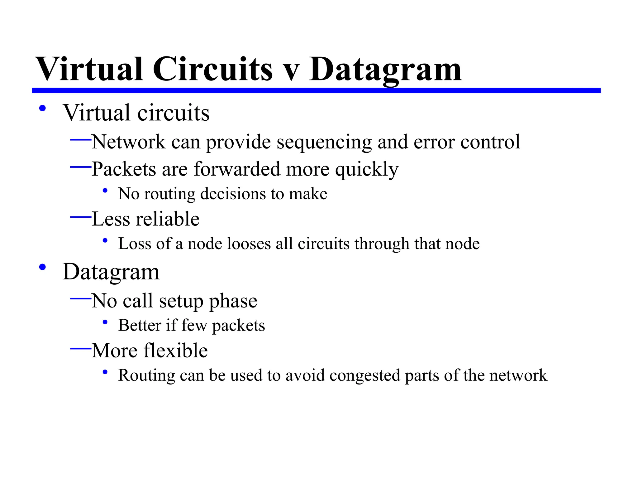
Virtual Circuits vDatagram
• Virtual circuits
—Network can provide sequencing and error control
—Packets are forwarded more quickly
• No routing decisions to make
—Less reliable
• Loss of a node looses all circuits through that node
• Datagram
—No call setup phase
• Better if few packets
—More flexible
• Routing can be used to avoid congested parts of the network
Cell Switching
• CellSwitching is a connection oriented switching technique in
which message is transmitted in the form of packets of same size.
• Cell switching is similar to packet switching as it operates in a
similar way to packet switching but uses small fixed length cells
for data transport.
• Used in Asynchronous Transfer Mode networks.
• Cell switching can handle multiple data types, i.e. voice, video
and
data. Moreover, cell switching is typically a high bandwidth and
high speed technology.
• Cell switching is essentially an attempt to combine the best of
circuit switching and packet switching.