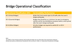
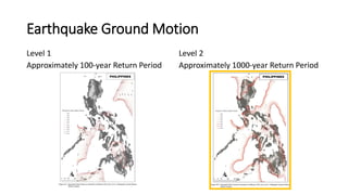
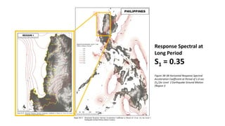
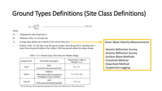
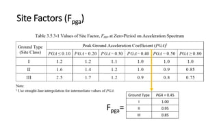
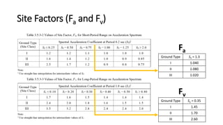
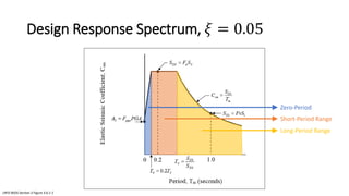
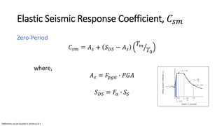
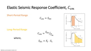
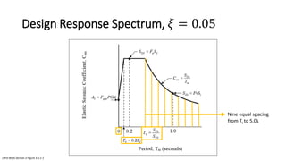
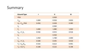
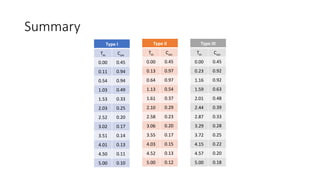
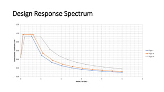
RESPONSE SPECTRUM
Bridges Division
Bureau of Design
The DPWH Guide Specifications for Seismic
Bridge Design is prepared under the
Project for Study on Improvement of
Bridges through Disaster Mitigating
Measure for Large Scale Earthquakes in
the Republic of the Philippines
Applicability of Specifications
These Specifications shall be taken to apply to the design and
construction of conventional bridges to resist the effects of earthquake
motion.
Conventional bridges:
• Flat Slab
• Reinforced Concrete Deck Girder (RCDG)
• Prestressed Concrete Deck Girder (PSCG)
Bridge Operational Classification
Operational Classification (OC) Serviceability Performance
OC-I (Critical Bridges) Brides that must remain open to all traffic after the Level 2
design earthquake.
OC-II (Essential Bridges) Bridges that should be as a minimum, be open to emergency
vehicles and for security/defense purposes within a short period
after the Level 2 design earthquake.
OC-III (Other Bridges) All other bridges not required to satisfy OC-I or OC-II
performance.
Note:
The DPWH or those having jurisdiction shall classify the bridge into one of the above three operational categories.
Detailed descriptions of Operational Classification (OC) can found in Table 3.2-1 Operational Classification of Bridges
Earthquake Ground Motion
Level 1
Approximately 100-year Return Period
Level 2
Approximately 1000-year Return Period
Peak Ground Acceleration
PGA = 0.45
Figure 3B-02 Horizontal Peak Ground
Acceleration Coefficient (PGA) for Level 2
Earthquake Ground Motion (Region I)
Response Spectral at
Short Period
SS = 0.9
Figure 3B-20 Horizontal Response Spectral
Acceleration Coefficient at Period of 0.20-sec
(SS) for Level 2 Earthquake Ground Motion
(Region I)
Response Spectral at
Long Period
S1 = 0.35
Figure 3B-38 Horizontal Response Spectral
Acceleration Coefficient at Period of 1.0-sec
(S1) for Level 2 Earthquake Ground Motion
(Region I)
Ground Types Definitions (Site Class Definitions)
Shear Wave Velocity Measurements
-Seismic Refraction Survey
-Seismic Reflection Survey
-Surface Wave Methods
-Crosshole Method
-Downhole Method
-Suspension Logging
Site Factors (Fpga)
Ground Type PGA = 0.45
I 1.00
II 0.95
III 0.85
Fpga=
Site Factors (Fa and Fv)
Ground Type S1 = 0.35
I 1.45
II 1.70
III 2.60
Ground Type SS = 1.3
I 1.040
II 1.080
III 1.020
Fa
Fv
Design Response Spectrum, 𝜉 = 0.05
LRFD BSDS Section 3 Figure 3.6.1-1
Zero-Period
Short-Period Range
Long-Period Range
Elastic Seismic Response Coefficient, 𝐶𝑠𝑚
Zero-Period
𝐶𝑠𝑚 = 𝐴𝑠 + 𝑆𝐷𝑆 − 𝐴𝑠 ൗ
𝑇𝑚
𝑇0
where,
𝐴𝑠 = 𝐹𝑝𝑔𝑎 ∙ 𝑃𝐺𝐴
𝑆𝐷𝑆 = 𝐹𝑎 ∙ 𝑆𝑆
Definitions can be located in Section 3.6.2
Elastic Seismic Response Coefficient, 𝐶𝑠𝑚
Short-Period Range
𝐶𝑠𝑚 = 𝑆𝐷𝑆
Long-Period Range
𝐶𝑠𝑚 = ൗ
𝑆𝐷1
𝑇𝑚
where,
𝑆𝐷1 = 𝐹𝑣 ⋅ 𝑆1
Definitions can be located in Section 3.6.2
Design Response Spectrum, 𝜉 = 0.05
LRFD BSDS Section 3 Figure 3.6.1-1
Nine equal spacing
from Ts to 5.0s
Summary
Ground Type I II III
PGA 0.450
Fpga 1.000 0.950 0.850
AS = Fpga PGA 0.450 0.428 0.383
SS 0.900
Fa 1.040 1.080 1.020
SDS = Fa SS 0.936 0.972 0.918
S1 0.350
Fv 1.450 1.700 2.600
SD1 = Fv S1 0.508 0.595 0.910
TS = SD1/SDS 0.542 0.612 0.991
TO = 0.2 TS 0.108 0.122 0.198
Summary
Type I
Tm Csm
0.00 0.45
0.11 0.94
0.54 0.94
1.03 0.49
1.53 0.33
2.03 0.25
2.52 0.20
3.02 0.17
3.51 0.14
4.01 0.13
4.50 0.11
5.00 0.10
Type II
Tm Csm
0.00 0.45
0.13 0.97
0.64 0.97
1.13 0.54
1.61 0.37
2.10 0.29
2.58 0.23
3.06 0.20
3.55 0.17
4.03 0.15
4.52 0.13
5.00 0.12
Type III
Tm Csm
0.00 0.45
0.23 0.92
1.16 0.92
1.59 0.63
2.01 0.48
2.44 0.39
2.87 0.33
3.29 0.28
3.72 0.25
4.15 0.22
4.57 0.20
5.00 0.18
Design Response Spectrum
0.00
0.20
0.40
0.60
0.80
1.00
1.20
0 1 2 3 4 5 6
Elastic
Seismic
Coefficient,
Csm
Period, Tm (sec)
Type I
Type II
Type III
End
Bridges Division

10-Response-Spectrum-Region-I.pdf

  • 1.
  • 2.
    The DPWH GuideSpecifications for Seismic Bridge Design is prepared under the Project for Study on Improvement of Bridges through Disaster Mitigating Measure for Large Scale Earthquakes in the Republic of the Philippines
  • 3.
    Applicability of Specifications TheseSpecifications shall be taken to apply to the design and construction of conventional bridges to resist the effects of earthquake motion. Conventional bridges: • Flat Slab • Reinforced Concrete Deck Girder (RCDG) • Prestressed Concrete Deck Girder (PSCG)
  • 4.
    Bridge Operational Classification OperationalClassification (OC) Serviceability Performance OC-I (Critical Bridges) Brides that must remain open to all traffic after the Level 2 design earthquake. OC-II (Essential Bridges) Bridges that should be as a minimum, be open to emergency vehicles and for security/defense purposes within a short period after the Level 2 design earthquake. OC-III (Other Bridges) All other bridges not required to satisfy OC-I or OC-II performance. Note: The DPWH or those having jurisdiction shall classify the bridge into one of the above three operational categories. Detailed descriptions of Operational Classification (OC) can found in Table 3.2-1 Operational Classification of Bridges
  • 5.
    Earthquake Ground Motion Level1 Approximately 100-year Return Period Level 2 Approximately 1000-year Return Period
  • 6.
    Peak Ground Acceleration PGA= 0.45 Figure 3B-02 Horizontal Peak Ground Acceleration Coefficient (PGA) for Level 2 Earthquake Ground Motion (Region I)
  • 7.
    Response Spectral at ShortPeriod SS = 0.9 Figure 3B-20 Horizontal Response Spectral Acceleration Coefficient at Period of 0.20-sec (SS) for Level 2 Earthquake Ground Motion (Region I)
  • 8.
    Response Spectral at LongPeriod S1 = 0.35 Figure 3B-38 Horizontal Response Spectral Acceleration Coefficient at Period of 1.0-sec (S1) for Level 2 Earthquake Ground Motion (Region I)
  • 9.
    Ground Types Definitions(Site Class Definitions) Shear Wave Velocity Measurements -Seismic Refraction Survey -Seismic Reflection Survey -Surface Wave Methods -Crosshole Method -Downhole Method -Suspension Logging
  • 10.
    Site Factors (Fpga) GroundType PGA = 0.45 I 1.00 II 0.95 III 0.85 Fpga=
  • 11.
    Site Factors (Faand Fv) Ground Type S1 = 0.35 I 1.45 II 1.70 III 2.60 Ground Type SS = 1.3 I 1.040 II 1.080 III 1.020 Fa Fv
  • 12.
    Design Response Spectrum,𝜉 = 0.05 LRFD BSDS Section 3 Figure 3.6.1-1 Zero-Period Short-Period Range Long-Period Range
  • 13.
    Elastic Seismic ResponseCoefficient, 𝐶𝑠𝑚 Zero-Period 𝐶𝑠𝑚 = 𝐴𝑠 + 𝑆𝐷𝑆 − 𝐴𝑠 ൗ 𝑇𝑚 𝑇0 where, 𝐴𝑠 = 𝐹𝑝𝑔𝑎 ∙ 𝑃𝐺𝐴 𝑆𝐷𝑆 = 𝐹𝑎 ∙ 𝑆𝑆 Definitions can be located in Section 3.6.2
  • 14.
    Elastic Seismic ResponseCoefficient, 𝐶𝑠𝑚 Short-Period Range 𝐶𝑠𝑚 = 𝑆𝐷𝑆 Long-Period Range 𝐶𝑠𝑚 = ൗ 𝑆𝐷1 𝑇𝑚 where, 𝑆𝐷1 = 𝐹𝑣 ⋅ 𝑆1 Definitions can be located in Section 3.6.2
  • 15.
    Design Response Spectrum,𝜉 = 0.05 LRFD BSDS Section 3 Figure 3.6.1-1 Nine equal spacing from Ts to 5.0s
  • 16.
    Summary Ground Type III III PGA 0.450 Fpga 1.000 0.950 0.850 AS = Fpga PGA 0.450 0.428 0.383 SS 0.900 Fa 1.040 1.080 1.020 SDS = Fa SS 0.936 0.972 0.918 S1 0.350 Fv 1.450 1.700 2.600 SD1 = Fv S1 0.508 0.595 0.910 TS = SD1/SDS 0.542 0.612 0.991 TO = 0.2 TS 0.108 0.122 0.198
  • 17.
    Summary Type I Tm Csm 0.000.45 0.11 0.94 0.54 0.94 1.03 0.49 1.53 0.33 2.03 0.25 2.52 0.20 3.02 0.17 3.51 0.14 4.01 0.13 4.50 0.11 5.00 0.10 Type II Tm Csm 0.00 0.45 0.13 0.97 0.64 0.97 1.13 0.54 1.61 0.37 2.10 0.29 2.58 0.23 3.06 0.20 3.55 0.17 4.03 0.15 4.52 0.13 5.00 0.12 Type III Tm Csm 0.00 0.45 0.23 0.92 1.16 0.92 1.59 0.63 2.01 0.48 2.44 0.39 2.87 0.33 3.29 0.28 3.72 0.25 4.15 0.22 4.57 0.20 5.00 0.18
  • 18.
    Design Response Spectrum 0.00 0.20 0.40 0.60 0.80 1.00 1.20 01 2 3 4 5 6 Elastic Seismic Coefficient, Csm Period, Tm (sec) Type I Type II Type III
  • 19.