SlideShare a Scribd company logo
1 of 46
Download to read offline
Honeywell HC²
Technical Design
Version: 1.0
Effective Date: 06-Jun-2014
Prepared by:
Danby Anchors
Paul Fries
Jon Chancellor
Elaine Kendall
Carl Kennedy
Don Lloyd
Rick Nurkka
Fabian Duarte
Mike Schmidt
Graham Shute
Project Name Hybrid Cloud Computing Platform HC2 Project ID 1019170
Service Owner Jacquet, Patrick Sponsor’s Organization HITS – SDD
Service Executive Kevin Hardenburg Date
Customer/Requestor Randy White Document Author Elaine Kendall
Initiation Date 05/01/2014 Target Completion Date 06/30/2015
Technical Design Document Page: 2 of 46
This document is published as part of an electronic document repository.
User is responsible for referencing the most recently published electronic version.
HONEYWELL CONFIDENTIAL
Table of Contents
Table of Contents......................................................................................................................... 2
1. Introduction.......................................................................................................................... 7
1.1 Purpose/Usage............................................................................................................................7
1.2 Executive Summary.....................................................................................................................7
1.3 Objective & Scope.......................................................................................................................7
1.4 Design Principles.........................................................................................................................8
1.4.1 Customer experience.........................................................................................................................8
1.4.2 Simplicity............................................................................................................................................8
1.4.3 Leverage existing work where possible .............................................................................................9
1.4.4 Modularity and flexibility...................................................................................................................9
1.4.5 Service integration.............................................................................................................................9
1.4.6 Service availability..............................................................................................................................9
1.4.7 Reliable delivery.................................................................................................................................9
1.5 Assumptions & Constraints.........................................................................................................9
1.5.1 Assumptions.......................................................................................................................................9
1.5.2 Constraints.......................................................................................................................................10
2. Topology and High-Level Design ........................................................................................ 10
2.1 Phase I.......................................................................................................................................10
2.1.1 High Level Logical Diagram ..............................................................................................................10
2.1.2 Tiered Deployment Basic Components............................................................................................11
2.1.3 Low Level Physical Design Diagram .................................................................................................12
2.1.4 Phase I: Beta.....................................................................................................................................12
2.1.5 Phase I: Production ..........................................................................................................................13
2.1.6 Disaster Recovery ............................................................................................................................13
2.2 Phase II......................................................................................................................................13
2.2.1 High Level Logical Diagram ..............................................................................................................13
2.2.2 Disaster Recovery ............................................................................................................................14
2.3 Phase III.....................................................................................................................................15
2.4 Phase IV.....................................................................................................................................15
3. Service Architecture ........................................................................................................... 15
3.1 User Requirements ...................................................................................................................15
3.1.1 Phase I..............................................................................................................................................15
3.1.2 Phase II.............................................................................................................................................15
3.2 Business Requirements.............................................................................................................15
3.2.1 Phase I..............................................................................................................................................15
3.2.2 Phase II.............................................................................................................................................16
3.3 Functional and Non-Functional Requirements.........................................................................16
3.4 Competitive Landscape Analysis...............................................................................................16
3.5 Service Components .................................................................................................................16
3.5.1 Phase I..............................................................................................................................................16
3.5.2 Phase II.............................................................................................................................................17
4. Service Specific Details....................................................................................................... 17
Technical Design Document Page: 3 of 46
This document is published as part of an electronic document repository.
User is responsible for referencing the most recently published electronic version.
HONEYWELL CONFIDENTIAL
4.1 Software....................................................................................................................................18
4.1.1 Phase I..............................................................................................................................................18
4.1.2 Phase II.............................................................................................................................................18
4.2 Hardware ..................................................................................................................................18
4.2.1 Phase I..............................................................................................................................................18
4.2.2 Phase II.............................................................................................................................................19
4.3 BMC Remedy.............................................................................................................................19
4.3.1 Phase I..............................................................................................................................................19
4.3.2 Phase II.............................................................................................................................................19
4.4 Host Name Database ................................................................................................................20
4.4.1 Phase I..............................................................................................................................................20
4.4.2 Phase II.............................................................................................................................................20
4.5 Infoblox .....................................................................................................................................20
4.5.1 Phase I..............................................................................................................................................20
4.5.2 Phase II.............................................................................................................................................21
4.6 Puppet.......................................................................................................................................21
4.6.1 Phase I..............................................................................................................................................21
4.6.2 Phase II.............................................................................................................................................21
4.7 TSF Database.............................................................................................................................21
4.7.1 Phase I..............................................................................................................................................21
4.7.2 Phase II.............................................................................................................................................21
4.8 ITBM Database..........................................................................................................................21
4.8.1 Phase I..............................................................................................................................................21
4.8.2 Phase II.............................................................................................................................................22
4.9 iPXE Build ..................................................................................................................................22
4.9.1 Phase I..............................................................................................................................................22
4.9.2 Phase II.............................................................................................................................................22
4.10 Client Support ...........................................................................................................................22
4.10.1 Phase I..............................................................................................................................................22
4.10.2 Phase II.............................................................................................................................................22
4.11 Legacy Support..........................................................................................................................22
4.12 Policies ......................................................................................................................................22
4.12.1 Phase I..............................................................................................................................................22
4.12.2 Phase II.............................................................................................................................................22
5. Availability Management ................................................................................................... 23
5.1 Component Summary...............................................................................................................23
5.1.1 Phase I..............................................................................................................................................23
5.1.2 Phase II.............................................................................................................................................23
5.1.2.1 ESXi Hypervisor ..............................................................................................................23
5.1.2.2 vCenter...........................................................................................................................24
5.1.2.3 Cisco Unified Computing System (UCS) .........................................................................24
5.1.2.4 Current Availability.........................................................................................................24
5.2 Targets ......................................................................................................................................25
5.2.1 Phase I..............................................................................................................................................25
5.2.2 Phase II.............................................................................................................................................25
5.3 Improvement Plans...................................................................................................................25
5.3.1 Phase I..............................................................................................................................................25
Technical Design Document Page: 4 of 46
This document is published as part of an electronic document repository.
User is responsible for referencing the most recently published electronic version.
HONEYWELL CONFIDENTIAL
5.3.2 Phase II.............................................................................................................................................25
5.4 Expectations or Opportunities..................................................................................................25
5.4.1 Phase I..............................................................................................................................................25
5.4.2 Phase II.............................................................................................................................................25
6. Capacity Management ....................................................................................................... 26
6.1 Compute....................................................................................................................................26
6.1.1 Phase I..............................................................................................................................................26
6.1.2 Phase II.............................................................................................................................................26
6.1.2.1 VCPU Algorithm Functionality........................................................................................26
6.2 Network ....................................................................................................................................26
6.2.1 Phase I..............................................................................................................................................26
6.2.2 Phase II.............................................................................................................................................27
6.3 Storage......................................................................................................................................27
6.3.1 Phase I..............................................................................................................................................27
6.3.1.1 Disk Space ......................................................................................................................27
6.3.1.2 Disk I/O...........................................................................................................................28
6.3.1.3 Storage Area Network (SAN)..........................................................................................28
6.3.1.4 SAN Benefits...................................................................................................................28
6.3.1.5 Storage Disk....................................................................................................................28
6.3.1.6 Storage Disk Benefits .....................................................................................................28
6.3.1.7 Storage Infrastructure....................................................................................................29
6.3.1.8 Disk Storage....................................................................................................................29
6.3.1.9 Storage Stack..................................................................................................................29
6.3.1.10 VSP Port Distribution......................................................................................................30
6.3.2 Phase II.............................................................................................................................................30
7. Continuity Management .................................................................................................... 30
7.1 Network Traffic .........................................................................................................................31
7.1.1 Phase I..............................................................................................................................................31
7.1.2 Phase II.............................................................................................................................................31
7.2 Backup.......................................................................................................................................31
7.2.1 Phase I..............................................................................................................................................31
7.2.2 Phase II.............................................................................................................................................31
7.3 Recovery....................................................................................................................................31
7.3.1 Phase I..............................................................................................................................................31
7.3.2 Phase II.............................................................................................................................................31
8. Log Management................................................................................................................ 32
8.1 CPO Log Management ..............................................................................................................32
8.1.1 Phase I..............................................................................................................................................32
8.1.2 Phase II.............................................................................................................................................33
8.2 Service Portal log management................................................................................................33
8.2.1 Phase I..............................................................................................................................................33
8.2.2 Phase II.............................................................................................................................................33
8.3 Host Log Management..............................................................................................................33
8.3.1 Phase I..............................................................................................................................................33
8.3.2 Phase II.............................................................................................................................................34
8.4 Central Virtual Service Management Log Management...........................................................34
Technical Design Document Page: 5 of 46
This document is published as part of an electronic document repository.
User is responsible for referencing the most recently published electronic version.
HONEYWELL CONFIDENTIAL
8.4.1 Phase I..............................................................................................................................................34
8.4.2 Phase II.............................................................................................................................................34
8.5 Sentinel Log Manager (SLM) Integration and Overview...........................................................34
8.5.1 Phase I..............................................................................................................................................34
8.5.2 Phase II.............................................................................................................................................35
9. Metrics Plan........................................................................................................................ 35
10. Monitoring & Event Management ..................................................................................... 35
10.1 Capacity Management Monitoring...........................................................................................35
10.1.1 Phase I..............................................................................................................................................35
10.1.2 Phase II.............................................................................................................................................35
10.2 Service Monitoring....................................................................................................................36
10.2.1 Phase I..............................................................................................................................................36
10.2.2 Phase II.............................................................................................................................................36
10.3 Application Monitoring.............................................................................................................36
10.3.1 Phase I..............................................................................................................................................36
10.3.2 Phase II.............................................................................................................................................36
11. Personas ............................................................................................................................. 36
11.1 Phase I.......................................................................................................................................36
11.2 Phases II to IV............................................................................................................................37
12. Security Management -...................................................................................................... 37
12.1 Security Groups.........................................................................................................................38
12.1.1 Phase I..............................................................................................................................................38
12.1.2 Phase II.............................................................................................................................................38
12.2 Requirements............................................................................................................................38
12.2.1 Phase I..............................................................................................................................................38
12.2.1 Phase II.............................................................................................................................................39
12.3 Data Privacy ..............................................................................................................................40
12.3.1 Phase I..............................................................................................................................................40
12.3.2 Phase II.............................................................................................................................................40
12.4 Restrictions ...............................................................................................................................40
12.4.1 Phase I..............................................................................................................................................40
12.4.2 Phase II.............................................................................................................................................40
12.5 Firewall Rules ............................................................................................................................41
12.5.1 Phase I..............................................................................................................................................41
12.5.1 Phase II.............................................................................................................................................41
12.6 Component Classification .........................................................................................................42
12.6.1 Phase I..............................................................................................................................................42
12.6.2 Phase II.............................................................................................................................................42
13. Supplier Management........................................................................................................ 42
13.1 Contract Determination............................................................................................................42
13.1.1 Phase I..............................................................................................................................................42
13.1.2 Phase II.............................................................................................................................................42
13.2 Responsibilities .........................................................................................................................42
13.2.1 Phase I..............................................................................................................................................42
13.2.2 Phase II.............................................................................................................................................42
13.3 Procedures................................................................................................................................42
Technical Design Document Page: 6 of 46
This document is published as part of an electronic document repository.
User is responsible for referencing the most recently published electronic version.
HONEYWELL CONFIDENTIAL
13.3.1 Phase I..............................................................................................................................................42
13.3.2 Phase II.............................................................................................................................................42
13.4 Access........................................................................................................................................43
13.4.1 Phase I..............................................................................................................................................43
13.4.2 Phase II.............................................................................................................................................43
14. Reports ............................................................................................................................... 43
14.1.1 Phase I..............................................................................................................................................43
14.1.2 Phase II.............................................................................................................................................43
15. Document History .............................................................................................................. 44
16. Document Approvals.......................................................................................................... 45
16.1 Document Approvals – Phase I .................................................................................................45
16.2 Document Approvals – Phase II................................................................................................46
Technical Design Document Page: 7 of 46
This document is published as part of an electronic document repository.
User is responsible for referencing the most recently published electronic version.
HONEYWELL CONFIDENTIAL
1. Introduction
1.1Purpose/Usage
The Technical Design document contains the technical components required for developing and
designing the service. It is produced by the Service Design and Deployment team with input from the
initial components identified in the Service Design Package (SDP), including, but not limited to:
 Business, Functional and Non-Functional Requirements
 Existing Standards
 Competitive Landscape Analysis
The following sections include information received from individuals and teams within SDD:
 Availability Management
 Capacity Management
 Continuity Management
The following sections include information individuals and teams outside of SDD:
 Metrics Plan
 Personas
 Monitoring & Event Management
1.2Executive Summary
Honeywell is creating an application hosting environment that will provide a flexible yet stable
alternative to classic server virtualization. The goal of this Hybrid Cloud Computing (HC²) service is to
supply hardware and software resource availability through readily accessible, managed online services.
The HC² platform is where hundreds of employees will be able to run their compute tools and processes
as online assets rather than actually installing them on their own computers. All of the workload
processing and file saving will be done in the cloud and users will plug into that cloud every day to do
their daily computing.
The most basic requirement of our cloud platform will be to manage and organize employee customer
workloads. These ‘workloads’ are independent applications or collections of code that can be executed
independently. For our purposes, workloads are considered well-planned services of very small compute
processes or complete applications where the technical details of the backend are kept away from the
customer user.
The Cloud Management Platform (CMP) will actively manage these dynamic workloads to monitor how
the applications are running as well as control the full lifecycle of the development environments. Cloud
utilization data will be evaluated in order to determine how much an individual department or SBG
should be charged for its use of the cloud services.
1.3Objective & Scope
HC² platform will provide access to behind the scenes advanced applications and high-end server assets
that will facilitate rapid workload provisioning and de-provisioning, while ensuring complete application
redundancy and resiliency for those workloads. It will further supply the ability to request application or
compute services from a self service web portal. All deployment will be automated, including integration
with various tools HITS uses today, such as Remedy CMDB, hostname selection tool, IP addresses, etc.
The figure below illustrates the services that will be provided and the timeline of the phased releases.
Technical Design Document Page: 8 of 46
This document is published as part of an electronic document repository.
User is responsible for referencing the most recently published electronic version.
HONEYWELL CONFIDENTIAL
Phase I will:
 Drive systematic design and creation of a foundation that will ultimately enable behind the scenes
system patching and upgrading for those applications that can support cloud aware infrastructure
 Enable developers to focus on development rather than infrastructure platform provisioning
 Provide a customer development IT platform alternative by replacing the need to stand up their own
environment or leveraging unsecured external cloud solutions
 Enable an effective and efficient path for customer IT development to procure cloud applications
through IaaS services (PaaS will be available in later phases)
 Be used to drive the systematic design and creation of a foundation that will ultimately enable a
robust and resilient application hosting environment for cloud compatible applications
 Provide a secure development environment behind the firewall that will eventually expand to the
intranet, extranet and ultimately hybrid cloud services
1.4Design Principles
HC² is being designed to provide an accelerated means for developers and application owners to
instantiate and orchestrate cloud workloads. It will leverage existing assets and Honeywell images
where available, while introducing top of the line scalable servers and network components. Any
available existing technologies will be leveraged to serve platform needs. The final HC² environment will
provide the required level of service availability with optimal service integration and flexibility.
1.4.1 Customer experience
HC² will be enabling an innovative computing platform by prioritizing design decisions around user
experience, considering how those decisions impact the customer and potential business impacts.
1.4.2 Simplicity
HC² will be designed to simplify administration of infrastructure platforms using automation and service
quality enhancements. Phase I will offer IAAS (Infrastructure as a Service) with Windows and Linux.
Some processes will be kept to a manual mode for time-to-market, rather than designing with full
functionality and for all IT services. Cloud architects will use this initial phase to standardize and simplify
services, processes and technology choices.
Using a manual process where necessary will be used in order to simplify design work and spread it over
time until exact consumer needs are better understood.
Technical Design Document Page: 9 of 46
This document is published as part of an electronic document repository.
User is responsible for referencing the most recently published electronic version.
HONEYWELL CONFIDENTIAL
1.4.3 Leverage existing work where possible
HC² will be designed to avoid disruptive and costly hardware and software updates that can adversely
affect current investments in technology or work already put into security and other policies. Cloud
architects will consider current investments and leverage existing assets and people where possible
while still replacing and modernizing where necessary.
1.4.4 Modularity and flexibility
Due to customer requirement variations and evolution, the platform will be designed with maximum
flexibility and minimal dependencies to account for the changeable environment. Cloud architects will
strive to provide ample flexibility, while adhering to the project/design service budget.
1.4.5 Service integration
Cloud services (IaaS, SaaS, PaaS) will be provided in phased releases, as the platform matures, to provide
the right combination for the best computing experience. The cloud service menu will be designed to
respond to different user types, groups and projects. The cloud architects will spend significant design
time on the integration of components.
1.4.6 Service availability
HC² will provide a service menu that clearly provides an understanding of the tradeoff between service
availability and pricing. The functional design will be in line with HITS service-level objectives (SLOs) and
service-level agreement (SLA).
1.4.7 Reliable delivery
HC² will be designed to offer maximum reliability with dependable service support options being
introduced in later phases. Cloud services will be integrated to provide a stable and trusted environment
while maximizing the use of proven technologies.
1.5Assumptions & Constraints
1.5.1 Assumptions
 Service primarily targeted toward Honeywell developers
 Ability to execute workloads at any time in batch mode or in real time
 Service capabilities will be supplied according to user account security settings
 The platform will be able to handle self-contained entities with no dependencies or entire
applications being used by groups of customers
 Submitter will be a SBG Architect/Focal point with delegated funding approval
 Infrastructure Service Request (ISR) ordering process is being deployed using the Transfer of
Services Form (TSF) process
 Finance will review and move TSF data to gold copy in future phases
 Internet capability from individual workloads (structured and controlled)
 Users will have console access to their workloads
 Workloads will be self-supported in Phase I
 Current server IP addresses will change as new subnets are added for automated networking
Technical Design Document Page: 10 of 46
This document is published as part of an electronic document repository.
User is responsible for referencing the most recently published electronic version.
HONEYWELL CONFIDENTIAL
1.5.2 Constraints
 Unable to host ITAR data in all phases of cloud
 Phase I will be developed on resources in DCW only
 Backups not included
o Snapshot only recovery
o 2 Snapshots per VM
 Phase I is self supported and will have no service desk interaction
 Micro-segmentation will not be supported in cloud due to current Firewall standards
 There is no current training plan in place for educating customers in the use of applications with
the cloud in mind
 There may be authorization and security policies associated with using particular cloud services
 At the time of this service release, the VM Build Rooms are only present in DCE/DCW
o So the service is only available in those 2 data centers
 Supports only Windows 2008 R2, Linux Redhat 5.x and 6.x guests
2. Topology and High-Level Design
2.1Phase I
2.1.1 High Level Logical Diagram
Phase I will be developed on resources in DCW only, VLAN backed and behind the firewall as diagrammed
here:
Technical Design Document Page: 11 of 46
This document is published as part of an electronic document repository.
User is responsible for referencing the most recently published electronic version.
HONEYWELL CONFIDENTIAL
2.1.2 Tiered Deployment Basic Components
The below diagram depicts clear segregation between the Web, Application and DB Tiers.
Application Tier
Internet
Perimeter Firewall
Web Server
IIS 7.0 | Apache 2.2
RDBM Server
MSSQL / Oracle
Web Tier Database Tier
App Zone
Firewall
DB Zone
Firewall
Prime Service Catalog
Process Orchestrator
Technical Design Document Page: 12 of 46
This document is published as part of an electronic document repository.
User is responsible for referencing the most recently published electronic version.
HONEYWELL CONFIDENTIAL
2.1.3 Low Level Physical Design Diagram
2.1.4 Phase I: Beta
The primary goal in this release is to provide an environment for users to assess the viability of their
cloud workloads in a secure setting.
This release will initially provide the following services to customers for beta testing:
 Automated Provisioning
 OS Linux RHEL6
 OS Windows 2008/2012
 Windows & Linux App dev environments (PaaS)
 Limited PaaS capabilities leveraging Cloud Foundry
 Puppet will be leveraged for OS and Application configuration
o Puppet will be in the background with no customer visibility
 This will provide a dev/test environment that defines self-service and virtualization capabilities while
providing embedded security prior to production rollout.
Technical Design Document Page: 13 of 46
This document is published as part of an electronic document repository.
User is responsible for referencing the most recently published electronic version.
HONEYWELL CONFIDENTIAL
2.1.5 Phase I: Production
Phase I Production will be developed on resources in DCW only, behind the firewall. The primary goal of
this release is to expand the development of Phase I applications to provide additional user offerings,
verify life cycle risks and increase resource pools. The environment will be dynamic and provide an
income stream through billing resource pools of virtual assets.
The Production release of Phase I will provide:
 More users
 Adjust workload functionality based on Phase I discoveries
 Improved service offerings
2.1.6 Disaster Recovery
Disaster recovery will be in place for the CMP only for Phase I. Phase I will not include customer workload
data recovery options.
2.2Phase II
2.2.1 High Level Logical Diagram
Technical Design Document Page: 14 of 46
This document is published as part of an electronic document repository.
User is responsible for referencing the most recently published electronic version.
HONEYWELL CONFIDENTIAL
Phase II will:
 Provide a robust classic server virtualization environment running in a live-production, private cloud
environment on the Honeywell intranet residing on resources in DCE & DCW
 Provide security compliant self-provisioning of cloud workloads with:
o Engineering Cloud Enabled applications
o Infrastructure Cloud Enabled applications
o Integration with Platform as a Service (PaaS) is planned for iterative releases
Disaster recovery will be provided in future releases.
2.2.2 Disaster Recovery
 Disaster recovery will be in place for the CMP only components for Phase II
o The Cloud Management Platform infrastructure will have an identical Hardware and VLAN
configuration in DCW and DCE
o The DCW CMP VM servers will be replicated from DCW to DCE and will be readily available
in the event of the CMT DR Event
o The technology used to facilitate the replication will be the vSphere Replication technology
that is now standard with the VMware ESXi Standard
 Recovery procedure will proceed as follows:
1. Bring CMP online
2. Bring all DBs online
3. Bring IAC specific VMs online
4. Leverage secondary VC to manage VMs from source host
 In order to provide Service Disaster Recovery, the service is to be developed with expansion through
multiple datacenters with similar hardware and identical hypervisor software versions
o This allows for the necessary portability of individual workloads from datacenter to datacenter
 Individual workload disaster recovery is covered in detail in the Continuity Section of this document
UsersNetwork Network
CMP Databases
CMP Databases
Database ReplicationPrimary Site (DCW)
DR Site (DCE)
VR Server
vCenter
Server
VR Server
vCenter
Server
CMP
VM
CMP
VM
CMP
VM
CMP
VM
CMP
VM
CMP
VM
vSphere Replication
OR
Storage Based Replication
CMP Host Cluster CMP Host Cluster
Storage Storage
Technical Design Document Page: 15 of 46
This document is published as part of an electronic document repository.
User is responsible for referencing the most recently published electronic version.
HONEYWELL CONFIDENTIAL
2.3Phase III
Phase III will be a live-production, DMZ cloud environment with internet capabilities residing on
resources in DCE & DCW. The primary goal of Phase III will be to provide internet facing workloads with
disaster recovery and PaaS. The full DR design will be included at that time.
2.4Phase IV
Phase IV will be a live-production, hybrid environment of internal and external resource offerings with
hardware residing in DCE & DCW. This phase will provide the capability to authenticate between VMs
server instances communicate with other server instances. It will provide public cloud services such as
Azure, Amazon, etc., additional resources on-demand and offer features available from external
providers that are not available internally, such as object storage.
3. Service Architecture
The Cloud Management Platform (CMP) will ultimately reside on the outside of the firewall, so the
workloads for Phase I that are spinning up will travel through the firewall. Phase II workloads will not reside
behind a firewall.
The Cloud Service will be released in phased deployments of increasing features and functionality.
3.1User Requirements
3.1.1 Phase I
The Cloud Management Platform in Phase I will have the following customer capabilities:
 Customer can Log in to the CMP
o Puppet template
 Customer can select services and applications from a Service Catalog
 The VM will be delivered based on the selections
 The customer will have access to the VM
o Console and SSH access
 Customer will be able to decommission the VM
3.1.2 Phase II
Users must have an LDAP EID.
3.2Business Requirements
3.2.1 Phase I
The Cloud Management Platform will:
 Provide an improved workload monitoring service for self-service provisioning
 Be built on a clustered/fault tolerant infrastructure, thereby reducing downtime
 Reduce end-to-end workload provisioning time
 Provide chargeback capabilities
Technical Design Document Page: 16 of 46
This document is published as part of an electronic document repository.
User is responsible for referencing the most recently published electronic version.
HONEYWELL CONFIDENTIAL
 Provide the ability to provision both internally as well as on an external Public Cloud (hybrid
model) to allow for finance charge back
 Allow end users to monitor workload performance and self adjust resources
 Include a PaaS offering with a fully integrated development environment
 Provide the ability to:
o Easily interface with existing systems
o HITS ownership of system administration
o Incorporate into existing user provisioning systems
o Deploy n-tier environments
o Support for web, middleware and database
 Meet compliance and security requirements and adhere to dependencies
 Leverage a self service web portal for Disaster Recovery rather than relying on the ISR process
3.2.2 Phase II
No additional business requirements are needed for Phase II.
3.3Functional and Non-Functional Requirements
The functional and non-functional requirements are extrapolated from the base business requirements
and shall include items such as:
Availability Continuity Interface Personas Solutioning
Capabilities Financial Metrics Security Support
Capacity Implementation Monitoring SLA Training
Please reference the SDP Requirements Traceability Document:
HC² Rqmts SDP 06
HITS Requirements_Traceability.xlsx
3.4Competitive Landscape Analysis
A full proof of concept was performed between VMware and Cisco solutions. Cisco CIAC was chosen.
Please reference the 08-HC²-Competitive-Landscape-Analysis:
08-HC²-Competitive-L
andscape-Analysis.xls
3.5Service Components
3.5.1 Phase I
 Dell R620 servers behind its own FW
 Design will facilitate single sign on accessibility
 VLAN backed network as described in the Cisco VLAN Orchestration High Level Design document
found in the Network section of this document
Technical Design Document Page: 17 of 46
This document is published as part of an electronic document repository.
User is responsible for referencing the most recently published electronic version.
HONEYWELL CONFIDENTIAL
 Each application or workload providing a business function is deployed into its own network layer
2 “container”
 Each virtual network can support up to a /24 assigned to it
o These IPs are assigned to each VM yet are not routed outside the virtual network
 Each container has 1+ routed IPs
o They are still RFC1918 addresses, but are routed on the EWN
 Additional IPs are used for things like HTTPS hosting sites where each branded site gets its own IP
so the SSL certificates work properly
o Normal use case is 1
 The routed IP is tied to a location
o If the location is moved, it is assigned a new routed IP
 Cloud Management Platform would update the DNS entries as part of the move
 The Cloud does not participate in the IGP
 The Cloud appears as a set of L2 connections to the datacenter fabric
 3 tiered apps are still done on 1 VLAN
3.5.2 Phase II
 Cisco UCS servers
 Design will facilitate single sign on accessibility
 VLAN backed network as described in the Cisco VLAN Orchestration High Level Design document
found in the Network section of this document
 Additional IP addresses can be requested for a cloud Virtual Server
o One production EWN
 (Enterprise Wide Network)
o See HC² RunBook for detailed instruction
 The routed IP address for a VM is tied to its specific location
o If a VM is required to move to a new location, an IP address can be requested in the target
location and the VM can be moved
o Moving a VM will require manual tasks from the EC support team
o The Cloud Management Platform would update the DNS entries as part of the move
 Allocate a generic IP address exactly the same as classic server virtualization procedures
 3 tiered apps are still done on 1 VLAN
4. Service Specific Details
The Service catalog will contain a list of service catalog items available to the customer, for example,
Windows 2008 R2, RHEL 6, LAMP Stack, etc.
When a customer places an order, IAC's internal automation processes the work to build the requested
workload. Once the build is complete, IAC will notify the customer via email and the provisioned workload
will be visible in the user’s management console.
HITS internal personnel will support the infrastructure required to run the provisioned workloads, i.e.
Physical compute hosts, Hypervisor, networking, etc, but will the workloads themselves are self supported
by the customer.
Future iterations will include a request process in the service catalog for "new" service catalog items.
Technical Design Document Page: 18 of 46
This document is published as part of an electronic document repository.
User is responsible for referencing the most recently published electronic version.
HONEYWELL CONFIDENTIAL
4.1Software
4.1.1 Phase I
 IAC bundle
o Process Orchestrator, PNSC (Prime Network Services Controller), Service Catalog, Cisco
Server Provisioner
 Infoblox
 Puppet
 Cloud Foundry
 VMware Hypervisor
 Windows/Linux
 SQL
4.1.2 Phase II
No additional software will be utilized for Phase II.
4.2Hardware
4.2.1 Phase I
 The following new servers are installed:
o 3 CMP, 3 Edge, 2 Firewall, 9 Compute
 1 Rack for Phase I
 Top of rack 10G switches
NOTE: Please reference SDP28 Service Catalog Content document for more information.
Technical Design Document Page: 19 of 46
This document is published as part of an electronic document repository.
User is responsible for referencing the most recently published electronic version.
HONEYWELL CONFIDENTIAL
4.2.2 Phase II
Phase II will use HITS Standard UCS hardware components. Please review the embedded Standards
document for detailed information.
4.3BMC Remedy
4.3.1 Phase I
The Remedy call interaction occurs via a WSDL API. Follow the link below to see the detailed solution for
setting up the web service interface to Remedy for various functions including CI Modify, CMT Create
/Modify, INC Create/Modify and Task Create/Modify.
Web_Service_Interfac
es_with_ITSM_v1_0_WithModifyRequirements.pdf
A Configuration Item (CI) is required to create, modify and maintain the CI record through the item life
cycle. Items such as vDC’s, VM’s, component relationships, etc. make up the hybrid cloud.
https://qremedy.dce.honeywell.com/arsys/WSDL/public/qarsys.honeywel
l.com/COE_AST_CIInterfaceCreate
CI Create/Modify QA
https://remedy.dcw.honeywell.com/arsys/WSDL/public/arsys.honeywell.c
om/COE_AST_CIInterfaceCreate
CI Create/Modify Prod
A Change Management Ticket (CMT) is required to create the CMT and modify it as it progresses through
the change. The CMT will also task individuals and/or automation to perform the task required to
complete the CMT. The CMT will use the CI Modify connector to update the CI.
https://qremedy.dce.honeywell.com/arsys/wsdl/public/qarsys.honeywell.
com/COE_CHG_ChangeInterface_Create
CMT Create/Modify QA
https://remedy.dcw.honeywell.com/arsys/WSDL/public/arsys.honeywell.c
om/COE_CHG_ChangeInterface_Create
CMT Create/Modify Prod
An Incident Ticket (INC) is required in creating and modifying the INC as it progresses through the
incident. The INC will task individuals and/or automation to perform tasks required to complete the INC.
https://qremedy.dce.honeywell.com/arsys/WSDL/public/qarsys.honeywel
l.com/COE_HPD_Incident_Interface_Create
INC Create QA
https://remedy.dcw.honeywell.com/arsys/WSDL/public/arsys.honeywell.c
om/COE_HPD_Incident_Interface_Create
INC Create Prod
http://10.216.22.29:8080/arsys/WSDL/public/de08u2516-
fwd.dce.honeywell.com/COE_HPD_Incident_Interface_Modify
INC Modify QA
https://remedy.dcw.honeywell.com/arsys/WSDL/public/qarsys.honeywell.
com/COE_HPD_Incident_Interface_Modify
INC Modify Prod
4.3.2 Phase II
In addition to Phase I functionality described above, Phase II will include the ability to create Remedy
Work Orders.
A Remedy Work Order will be leveraged to facilitate specific tasks within server build processes. This will
be a standard Work Order creation process that will be leveraged by a variety of specific server build
tasks. The Remedy Work Order will leverage the Remedy CMDB to track progression of tasks throughout
the Production Server Build process. Once all Work Orders are completed, the server provisioning
process will complete and move to the finalization phases of the overall cloud deployment function.
Technical Design Document Page: 20 of 46
This document is published as part of an electronic document repository.
User is responsible for referencing the most recently published electronic version.
HONEYWELL CONFIDENTIAL
4.4Host Name Database
4.4.1 Phase I
This service integrates with the Host Name database. After receiving a Hostname, the workflow will
proceed to Infoblox to receive IP and DNS. The following list details the interaction:
 CMP interaction occurs via a WSDL API call to the host name db
http://10.192.24.109:90/CreateHostNameUtil.asmx?WSDL Host Name QA
http://10.192.24.108:91/CreateHostNameUtil.asmx?WSDL Host Name Prod
 CMP will have to pass the following variables to request a hostname:
o Static
 LID code – unique for cloud
 Type = Virtual Host
 ISR#
 Model #
o Dynamic
 OS Type = W (= Windows) or U (=Linux)
 Assigned To:
 Assigned By:
 Notes (optional field)
 Example of the return; hccpw12345
o NOTE: A Host name must never be reused
4.4.2 Phase II
No changes are to be made to the Host Name Database architecture for Phase II.
4.5Infoblox
4.5.1 Phase I
This service integrates with Infoblox, which will be configured identically in DCE and DCW.
 Stand up a dedicated Infoblox environment
 CMP will interact with Infoblox via a provided plug-in for the Cisco process orchestrator
o CMP will be able to reserve IP addresses
o CMP will be able to create DNS ‘A’ records
o Return IP addresses back to the pool upon deprovisioning
o Remove ‘A’ records upon deprovisioning
 Will act as authoritative for a dedicated TLD for cloud
o The existing enterprise DNS system [IP control] will have a forwarder record that points
to Infoblox for the cloud TLD
 CIAC comes with sample code for Infoblox integration out of the box via Perl Infoblox module
 Customers can also invoke Infoblox via the WAPI REST API**, which was tested using Infoblox
IPAM Express free software through the following steps:
o Retrieve Port groups and UCS VLANs
o Infoblox Get IP Address via WAPI
o Set Multiple Variables
Technical Design Document Page: 21 of 46
This document is published as part of an electronic document repository.
User is responsible for referencing the most recently published electronic version.
HONEYWELL CONFIDENTIAL
**NOTE: There are apparent limitations. There could be a concurrency issue where multiple VM’s can
request an IP and get the same address. This needs to be addressed.
4.5.2 Phase II
No changes are being made to Infoblox design are being made for Phase II.
4.6Puppet
4.6.1 Phase I
 Will run on RHEL 6 servers
 Will be deployed as 3 dedicated Linux VMs; Puppet Master, Puppet Database, Puppet Console
 During the provisioning of a workload in the CMP, the infrastructure support team will be able to
customize application availability and workload structure based on templates created in Puppet
o For example, customers can create a Linux VM and choose to enable Apache Web service
4.6.2 Phase II
Puppet for Phase II will include the following design requirements:
 Puppet Master will reside within the CMP environment for each datacenter
 Puppet architecture will facilitate management of workloads in all four zones of the datacenter
 License management will be based on a distributed model
 Puppet will be leverage for adding applications such as Oracle to Linux VM Workloads
 Multiple Puppet Masters will be leveraged throughout the Honeywell Enterprise
 Puppet will evaluated for configuration management usage
4.7TSF Database
4.7.1 Phase I
The service integrates with the TSF database. Once automation finishes gathering server information, it
pulls cost data from the TSF database and presents costs to User and SBG Financial approver work flow.
TSF DB interaction occurs via a SQL call to the TSF db. DB calls directly for TSF database. No Web service is
available.
AZ18U659.honeywell.com - SQL DB: EREC TSF QA Read
AZ18U658.honeywell.com - SQL DB: EREC TSF Prod Read
AZ18U659.honeywell.com - SQL DB: EREC TSF QA Write
AZ18U658.honeywell.com - SQL DB: EREC TSF Prod Write
4.7.2 Phase II
No changes to be made for Phase II.
4.8ITBM Database
4.8.1 Phase I
The ITBM Database is out of scope for Phase I.
Technical Design Document Page: 22 of 46
This document is published as part of an electronic document repository.
User is responsible for referencing the most recently published electronic version.
HONEYWELL CONFIDENTIAL
4.8.2 Phase II
 The finance TSF database will be used with the strategic plan to migrate to the BMC ITBM module
 Initially on the rollout of the ITBM module it will feed the TSF DB for an extended term until all
services are developed into the Service Integration Project sometime in 2015
 Current technical requirements are not defined for the ITBM SI project and therefore at the writing
of this document creation interaction and use of the ITBM module is TBD
4.9iPXE Build
4.9.1 Phase I
This service integrates with iPXE build. Once the CMP automation gathers the information necessary for
server configuration and financial approvals are completed, the CMP will initiate and interact with iPXE
and create the VDC’s and VMs as defined in the service request.
4.9.2 Phase II
There will be no change to the design for Phase II. However, a change to the network design for Phase II
has resulted in the ability to centralize iPXE VMs, which permits the iPXE component to accommodate
workloads for both Phase I and Phase II workloads in HC2.
4.10 Client Support
4.10.1 Phase I
No specific client support is required. Customers will connect to the VM workloads by leveraging the
standard processes for their specific OS. End users do not have individual VM workload console access.
4.10.2 Phase II
No changes are being made for Phase II.
4.11 Legacy Support
This is not applicable as this is a new service.
4.12 Policies
4.12.1 Phase I
No specific policies are in place for Phase I.
4.12.2 Phase II
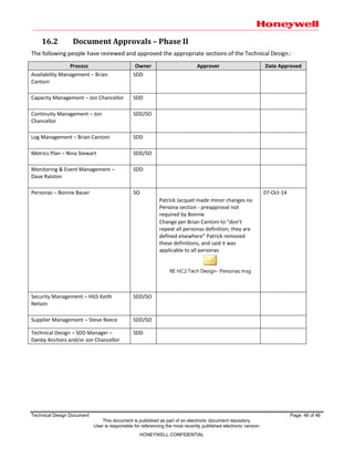
 Cloning Policy
A VM Workload clone is defined as an exact, file level copy of another VM workload. Clones are only
allowed in the existing production virtualization service if the operating system of the copy has
undergone the necessary sterilization procedures. This is required to ensure that the unique identifiers
on each software installation remain unique on the Honeywell production network.
Technical Design Document Page: 23 of 46
This document is published as part of an electronic document repository.
User is responsible for referencing the most recently published electronic version.
HONEYWELL CONFIDENTIAL
 Snapshot Policy
A snapshot is a feature of virtualization that allows a VM workload to be placed into a specific frozen
mode for a short, specified duration of time. During this timeframe, all changes to the VM workload are
stored in a temporary delta file. The VM Policy allows for durations of up to 72 hours. Longer timeframes
place the VM at risk of corruption and will take longer times to commit any changes to the original VM.
All snapshots are to be executed under the existing Honeywell Change Management Policy (CMP).
5. Availability Management
5.1Component Summary
5.1.1 Phase I
Availability for Phase I is focused on CMP functionality only. Support services are limited to HITS internal
personnel. Customer workloads will be self supported. There are no support personnel who will be
providing availability support outside of business hours. There are no reporting functions available in
Phase I. Resiliency in the individual components due to the redundancy of the underlying infrastructure
made available by the hypervisor platform.
5.1.2 Phase II
The table below lists the current component summary for Phase II.
Service Outage Impact Description Target
Projected
Availability
Windows 0.7 hrs/mo of
unplanned
down time
- Failure of the underlying physical hypervisor
is mitigated by automatically restarting them
onto a surviving node
- OS support has the same SLA from the
supplier on both physical and virtual servers
Gold
Support
99.9 % 99.9 %
ESX 0.7 hrs/mo of
unplanned
down time
- Failure of vSphere Server will result in
outages on all VMs that are hosted on it
Gold
Support
99.9 % 99.9 %
RHEL 0.7 hrs/mo of
unplanned
down time
- Failure of the underlying physical hypervisor
is mitigated by automatically restarting them
onto a surviving node
- OS support has the same SLA from the
supplier on both physical and virtual servers
Gold
Support
99.9 % 99.9 %
Storage 0.7 hrs/mo of
unplanned
down time
Failure of the underlying physical storage
system will affect all VMs hosted on that
storage system
Gold
Support
99.9 % 99.9 %
5.1.2.1 ESXi Hypervisor
Availability will be partially managed through the built-in High Availability (HA) feature in the
VMware ESXi Hypervisor. In the event of a single ESXi Host failure, other ESXi Hosts in the same
cluster or group of hosts will begin systematically bringing the VMs that were running on the host at
the time of failure, back online. The Recovery Time Objective (RTO) of these individual workloads,
considered one VM instance, is approximately 120 seconds.
Technical Design Document Page: 24 of 46
This document is published as part of an electronic document repository.
User is responsible for referencing the most recently published electronic version.
HONEYWELL CONFIDENTIAL
5.1.2.2 vCenter
The VMware vCenter Server has a feature called vMotion, which facilitates additional Service
Availability. If planned or emergency changes require a single ESXi Host be taken offline, server
administrators can leverage vMotion to evacuate a single node with no outage to the workloads.
This allows 100% uptime for VMs, while individual ESXi hosts go through regular maintenance.
Because a workload resides on shared SAN LUNs that are presented to a group of physical ESXi
hosts, a VM is able to properly function on any of the available ESXi hosts.
Cluster groups will be built with an ‘N+1’ configuration, where ‘N’ is defined as the total amount of
compute required to host all current customer workloads. This design ensures that a single ESXi host
outage will not impact performance.
Each physical ESXi host will have two Converged Network Adapters (CNA) that will facilitate
additional availability by providing redundancy for network or SAN, planned or unplanned
connectivity outages.
5.1.2.3 Cisco Unified Computing System (UCS)
The Cisco UCS hardware chassis has four power supplies to facilitate the availability of the power
system. In case of a single or dual power supply failure or power feed failure, the remaining power
supplies will continue supporting the system until full power is restored.
There are two Fabric Interconnects (FI) in each UCS Point of Delivery (POD). All chassis and blades
attached to FIs are part of a single, highly available management domain. In the event of a planned
or unplanned outage to a single FI, the second FI will continue to provide all required connectivity
for network and SAN to ensure there are no service outages.
Each UCS Chassis is configured with redundant IO modules and four 10GB uplinks to the FIs. This
configuration ensures that a single IO Module, planned or unplanned outage, will not impact
availability and will provide the necessary redundancy of the uplinks.
NOTE: For UCS servers, all ESXi boot LUNs are SAN-based for additional availability. The SAN
infrastructure will not be detailed here.
For non-UCS ESXi hosts, each server has dual hard drives configured with Raid1. If a single hard drive
fails, the second will immediately take over and continue to function seamlessly.
5.1.2.4 Current Availability
The service components and capabilities detailed above will allow the achievement of the Projected
Availability Metrics provided in the table below.
Service Outage Impact Description
Target
%
Projected
Availability
Virtualization
Infrastructure
0.36
hrs/mo of
unplanned
down time
- Failure of the vCenter will not result in reduced
availability. The workloads continue to run as
expected without the VC.
- Failure of one vSphere node will result in a VM
outages/reduced availability since the VM will
be momentarily offline.
- Failure of multiple vSphere nodes will result in
significant downtime
Clustered
Gold
Support
99.95 99.95
Technical Design Document Page: 25 of 46
This document is published as part of an electronic document repository.
User is responsible for referencing the most recently published electronic version.
HONEYWELL CONFIDENTIAL
Service Outage Impact Description
Target
%
Projected
Availability
Virtual
Workloads
0.7 hrs/mo
of
unplanned
down time
- Failure of the underlying physical hypervisor is
mitigated by automatically restarting them onto
a surviving node (HA)
- OS support has the same SLA from the supplier
on both physical and virtual servers
Gold
Support
99.90 99.90
5.2Targets
5.2.1 Phase I
CMP service availability target will have an internal OLA of no less than 3 business days.
5.2.2 Phase II
No Targeted Availability Metrics are planned at this time.
5.3Improvement Plans
5.3.1 Phase I
Availability support services will be offered in future production releases and will be delivered in a 3 tier
service offering according to billing structure.
5.3.2 Phase II
No changes are being made for Phase II.
5.4Expectations or Opportunities
5.4.1 Phase I
5.4.2 Phase II
Phase II production release service availability target is 7x24x365.
Future phased release targets are
 Gold tier support
o Requirement matches SLA of 99.9%
o Workload uptime expectation is 99.9% for CMP handles
o 4 hour response SLA
 Silver tier support
o Requirement matches SLA of 99.0%
o Workload uptime expectation is 99% for CMP handles
o 8 hour response SLA
 Bronze tier support
o Requirement matches SLA of 95.0%
o Workload uptime expectation is 95% for CMP handles
o 12 x 5 Business days w/ 3 day SLA
Technical Design Document Page: 26 of 46
This document is published as part of an electronic document repository.
User is responsible for referencing the most recently published electronic version.
HONEYWELL CONFIDENTIAL
6. Capacity Management
Capacity management is controlled in three categories; Compute, Network and Storage.
6.1Compute
6.1.1 Phase I
CPU and memory resources per host will be monitored and a host deemed 100% utilized when 80% of
CPU capacity has been allocated.
6.1.2 Phase II
The primary resource constraint in the cloud service is shared CPU. Due to this capacity constraint, an
algorithm has been developed to measure and maintain a VCPU ratio ranging from 4-1 to 5-1.
6.1.2.1 VCPU Algorithm Functionality
The number of CPU cores on a physical server or group of servers (also referred to as a cluster) are
summed and doubled for hyper threading. This provides the number of cores available to service
VM workload needs. Each VM workload has a specific VCPU amount assigned to it at all times. This
number can range from one to sixteen depending on its configuration at the time of report
generation. For example, an Ivy Bridge-based, two socket physical server will have a total of 48
available cores. VM workload totals on this single physical server can be 192, which will generate a
VCPU ratio of 4-1. A VM workload total of 240 would yield a VCPU ratio of 5-1 and is deemed
unacceptable. Please see the table below for a summary:
VCPU Ratios up to 4-1 Acceptable Green
VCPU Ratios of 4-1 to 5-1 Warning Yellow
VCPU Ratios above 5-1 Alert Red
Total RAM capacity is a secondary factor and is also monitored to prevent performance problems.
Each physical server is procured with 256 GB of RAM and total RAM usage remains below 100%
utilized since the most constrained resource is VCPU. As more physical servers are procured to
expand capability, RAM is also expanded and maintains the same level of overall underutilization.
The standard RAM size will be upgraded from 256 GB to 384 GB in Q4 of 2014. This is primarily due
to the introduction of 32 and 64 GB DIMMS to the industry, thus driving down individual 16GB
DIMM average costs. The 384 GB of RAM is provided by 24 DIMMS of 16 GB capacity per DIMM and
is now at a moderate price point. This adjustment to the standard physical host will ensure RAM
capacity is tracked, but no action will be required for this metric.
6.2Network
6.2.1 Phase I
 Bandwidth
There are two Cisco Nexus 5596UP** switches are installed to facilitate uplink/aggregated
connectivity for top of cabinet installed fabric extenders (FEX) and two Checkpoint firewalls (Ref the
Firewall Rules section of this document) isolating the data center network. This pair can support ten
pairs of Cisco Nexus 2232PP FEXs which in turn support 32 physical 1Ru servers per cabinet.
Technical Design Document Page: 27 of 46
This document is published as part of an electronic document repository.
User is responsible for referencing the most recently published electronic version.
HONEYWELL CONFIDENTIAL
There are two Cisco Nexus 2232 FEXs per cabinet installed for physical bandwidth with 40Gb of active
uplinks per Cisco Nexus 2232 FEX (80Gb possible with additional cabling), to facilitate direct server
Converged Network Adapter (CNA) connectivity.
The effective bandwidth in and out of the cloud infrastructure is 10Gb, based on lowest active uplink
size being one 10Gb uplink to each Checkpoint firewall (installed as active/standby pair).
** NOTE: The Cisco Nexus 5596PP switches will be replaced as soon as permanent Cisco Nexus
5672PP are received. This will change our final capacity which will be detailed at that time.
 VLANs
o Management VLANs have been configured to support switch management
o Functional VLANs will be dynamically configured by the cloud management platform for each
set of provisioned VMs
o Please reference the Cisco VLAN Orchestration High Level Design document
HC²_Honeywell_VLAN
_Orchestration_HLD_v2.pdf
 Ports
Cabinet AX120 contains two Nexus 2232PP FEXs to support 32 10Gb Ethernet/FCoE ports and one
Nexus 2248TP to support 32 1Gb Ethernet twisted pair connections implemented for remote console
access, one per server. Cabinet capacity is designed for 32 physical 1RU servers per cabinet, one CNA
connection per FEX, two 10Gb connections and one 1Gb Ethernet remote console port per server.
6.2.2 Phase II
No changes are being made for Phase II.
6.3Storage
6.3.1 Phase I
6.3.1.1 Disk Space
The Honeywell Disk Storage Environment provides the storage capacities necessary to meet the
demands of the enterprise. Storage Array disk drives are ordered on a quarterly basis to meet the
growing demand. Forecasting, trending and customer demand are used to determine the size of the
disk purchase that will be required.
Hitachi Storage Arrays are also designed to allow massive scaling with multiple tiers of disk
performance.
The Virtual Storage Platform can scale to a maximum of 2,521TB Maximum Storage System Capacity
(Physical Capacity). In addition to the massive scale out, VSP platforms have the capability to
‘virtualize’ external disk arrays to provide additional storage capacity.
Currently, the Honeywell environment virtualizes Hitachi Unified Storage (HUS) platforms behind
the Virtual Storage Platform. The HUS can scale to a maximum of 4,511 TB Maximum Storage
System Capacity (Physical Capacity).
Technical Design Document Page: 28 of 46
This document is published as part of an electronic document repository.
User is responsible for referencing the most recently published electronic version.
HONEYWELL CONFIDENTIAL
6.3.1.2 Disk I/O
Honeywell’s current vendor for Block Storage Architecture is Hitachi Data Systems. Currently,
Hitachi Block Storage Arrays deployed within Honeywell are Virtual Storage Platform (VSP),
Universal Storage Platform V (USPV) and Hitachi Unified Storage (HUS). Hitachi Storage Arrays are
designed to meet the needs of high performance enterprise environment.
 Storage Array Disk
Hitachi Storage Arrays come with a variety of disk options ranging from Steady State Drives to
Serial Attached Storage Drives. The storage team, upon request can provide a list of all drive
types and Below is a table of drives available on the storage platform and the
Drive Type Drive Speed RPM Drive Size Interface data transfer
rate (Gbps)
Internal data
transfer rate (MB/s)
15K 136GB 6 176.1 to 242
SAS 10K 300GB 6 194.3 to 283.4
SAS 10K 600GB 6 152.4 to 253.6
SAS 10K 900GB 6 164.9 to 279
 Storage Array Cache
Hitachi Storage Arrays provide caching capabilities to improve Write Response
Acknowledgement times. The Hitachi Storage Arrays are designed to have as low as
Number of Cache Memory
Adapter
1 2 3 4 5 6 7 8
Cache Memory Capacity
(GB)
32 to
128
64 to
256
96 to
384
128 to
512
160 to
640
192 to
768
224 to
896
256 to
1024
 Storage Array Fibre Channel Ports
Hitachi Storage Arrays are capable of providing great capacity of Read/Write
Port Type Speed
Fibre Channel Adapter 200 / 400 / 800 MB/s
Fiber Channel over Ethernet (FCOE) 10Gb/s
6.3.1.3 Storage Area Network (SAN)
 Cisco MDS Technologies
 Cisco UCS FCOE Technology of Day 1
6.3.1.4 SAN Benefits
 Unified Network allowing transition to FCOE
 FCOE is installed and configured in the production environment
 All Storage arrays accessible from fabric
6.3.1.5 Storage Disk
 Hitachi Virtual Storage Platform (VSP)
 Hitachi Unified Storage (HUS)
6.3.1.6 Storage Disk Benefits
 Storage Virtualization Capabilities
 VM Integration Capabilities
Technical Design Document Page: 29 of 46
This document is published as part of an electronic document repository.
User is responsible for referencing the most recently published electronic version.
HONEYWELL CONFIDENTIAL
 Flexibility (Cache/Storage/Ports)
 Migration between tiers – seamless
 Resources can be dedicated ; Ports, Storage
 Continual Expansion
 Disaster Recover Options
o Point in Time Snapshots
o Copies Within Array
o Inter-Array Replication
o Remote Site Replication
6.3.1.7 Storage Infrastructure
 Cisco Fabric with FCOE available in production and ready for transition for HC² Project
6.3.1.8 Disk Storage
 Dedicated Pool of Storage to HC²
o 88TB Usable Storage
o Hitachi Unified Storage
o Performance Centric
o Non-Thin Provisioned
 Function can be made available if needed
 4 Fibre Channel Ports on the VSP Dedicated to VM hosting with 8Gb Fibre Channel Speeds
 Proven Technology for 3 years
 HDS Assessment of VM/Storage Performance
o Performance assessment complete with recommended actions given
o Capgemini will implement changes moving forward
o Storage Manager for vCenter is currently installed in the Lab and ready for testing
6.3.1.9 Storage Stack
Technical Design Document Page: 30 of 46
This document is published as part of an electronic document repository.
User is responsible for referencing the most recently published electronic version.
HONEYWELL CONFIDENTIAL
6.3.1.10 VSP Port Distribution
6.3.2 Phase II
No changes are being made for Phase II.
7. Continuity Management
Hardware fault tolerance will be leveraged to make certain components of the CMP are highly available.
Cisco has provided the necessary networking infrastructure designs and best practice recommendation to
support the Private Cloud. The document is not a line by line configuration design document. It is a
discussion of the design, protocol that will be used and best practices. Reference the HC² Honeywell Cloud
Networking Infrastructure Design document:
HC2_Honeywell_Clou
d_Networking_Infrastructure_Design_LATEST.pdf
Technical Design Document Page: 31 of 46
This document is published as part of an electronic document repository.
User is responsible for referencing the most recently published electronic version.
HONEYWELL CONFIDENTIAL
7.1Network Traffic
7.1.1 Phase I
 Host connections to SAN storage arrays will use Multihop FCoE (Fiber Channel over Ethernet)
o FCoE functionality requires hosts be directly cabled to Cisco Nexus switching platform
capable of encapsulating Fiber Channel traffic (i.e. Cisco Nexus 5000 Series)
 Using Dell R620, 1U servers with FCoE for access to storage for initial project
o This may update as the project progresses
 Dual 10Gb connections will be provided on each Hypervisor for Ethernet traffic
o Connects to separate top-of-rack Cisco Fabric Extenders (FEX)s
 Each FEX connects to a Cisco Nexus 5k in standard leaf/spine architecture
o All VM network traffic will utilize these connections
7.1.2 Phase II
No changes are being made for Phase II.
7.2Backup
7.2.1 Phase I
Existing Honeywell backup procedures owned by the Honeywell Storage and Backup team will be used to
backup CMP virtual machines as well as the CMP itself, vCenter and supporting services databases.
Workloads will not be backed up in Phase I.
7.2.2 Phase II
VM servers are backed up daily by an ESXi-based backup process that allows for a complete image
restore onsite or remote. In the event of a site failure, the HITS backup team can execute a system
restore using a copy of the backup image available at a select remote site. The Backup Team will
determine the specific location of the offsite image. This process will be invoked through the existing
HITS Incident Management process or existing HITS Major Incident Management process.
NOTE: Recovery Point Objective (RPO) and Recovery Time Objective (RTO) are currently unavailable as
they cannot be determined or Guaranteed.
7.3Recovery
7.3.1 Phase I
System Recovery will consist of recovering the databases first and then the VMs will be restored and
connected to the recovered databases.
7.3.2 Phase II
HC² provides two different VM recovery options in different datacenters to ensure service continuity if a
major outage prevents resurrecting the virtualization service locally. They are NetBackup-based and
VSphere replication-based restore processes.
Technical Design Document Page: 32 of 46
This document is published as part of an electronic document repository.
User is responsible for referencing the most recently published electronic version.
HONEYWELL CONFIDENTIAL
When executed in large volumes, both processes will require aggressive action plans to shut down
unnecessary VMs in the target datacenter in order to provide available compute and storage resources
required to run incoming workloads. They must only be executed under the HITS Major Incident process
as it will require prior approval and active engagement from all Honeywell IT Leadership teams. SBG IT
Leadership will provide a list of discretionary VM servers to the Server Administration team conducting
the VM restores. These VMs will be shut down as target VMs are being brought online. The shutdown
and restore order are insignificant as VMware ESXi Hypervisor is able to manage VM environments in an
over-provisioned manner for a short period of time.
For workloads that are preconfigured as being protected by the VSphere replication service, an additional
VM recovery option will be available. The DCE and DCW intranet zones will be configured with a VMware
replication appliance that will manage the remote synchronization of preconfigured VM Servers. Each
server included in this service will be individually configured and managed in the tool and will be set up
to replicate an offline copy of the VM Server. This offline copy will be an exact copy of the original VM to
include the original IP address. In the event of a production system restore, a Server Administrator will
execute the following steps to bring the VM online:
1. Initiate or stop replication (if required)
2. Power up the offline clone of the source server
3. Log into the server with the local administrator account
4. Update the IP address and DNS to a provided or predetermined IP address and validate network
connectivity
5. Reboot VM server and validate the server can be accessed via an active directory account
Once completed, the Application Owner will execute the following:
1. Log into the VM with their administrative account, which will be the same account they have
used on the previous VM server in the source datacenter
2. Execute any application specific tasks required to bring the application online with the new IP
Address
3. Leverage the HITS incident management process to have any application specific DNS entries
updated to reflect the new IP address (if not predefined in an application DR plan)
This service will provide a minimum RPO of 15 minutes. Shorter RPO recovery times cannot be
guaranteed with the current offering. No RTO timeframes are provided since RTO is to be determined
by the specific condition behind each event. An approximate application RTO could be 4 hours, but
cannot be guaranteed as all DR situations could have impacting scenarios that will delay the recovery.
VM recovery priority is to be provided by the SBG and HITS leadership teams and will determine
individual VM RTO. Based on priorities and available resources, it is possible that a RTO could be over
72 hours due to a forced ranking of priority.
8. Log Management
8.1CPO Log Management
8.1.1 Phase I
This service is not applicable for Phase I as there will be no data storage and no logs kept.
Technical Design Document Page: 33 of 46
This document is published as part of an electronic document repository.
User is responsible for referencing the most recently published electronic version.
HONEYWELL CONFIDENTIAL
8.1.2 Phase II
 The cloud support team will review the CPO logs to identify failed build tasks and identify root
causes of each
 This will be executed on a weekly basis and a report will be created based on the severity and
frequency
o The CPO log data will also be used for troubleshooting new workflow creations, changes
to existing workflows, and validation that CPO changes have not caused other failures or
errors in the workload
 Total timeframe of a end to end server build
8.2Service Portal log management
8.2.1 Phase I
This service is not applicable for Phase I as there will be no data storage and no logs kept.
8.2.2 Phase II
Log management for the service portal will provide data pertaining to the number of users who request
VM’s and their associated business groups on a weekly basis. The log information can be used to report
on the following metrics:
 VM workloads that have been requested but were never approved
 Quantity of services deployed to different available environments over a certain time period
 Number of types of applications deployed over a certain period
 Quantity of servers automatically decommissioned vs. manually decommissioned
 Number of failed logins to the portal
 Number of successful logins to the portal
 Length of average leases
 Quantity of VM workloads coming up on lease expiration
 Division of support types being ordered (example 99% gold and 1% Bronze)
8.3Host Log Management
8.3.1 Phase I
This service is not applicable for Phase I as there will be no data storage and no logs kept. Please
reference: Specific Use Case Networks (SUCN) – specifically:
Section 4.1
Honeywell utilizes distinct zones of trust, they are un-trusted, semi-trusted, and trusted. These zones
of trust within the specific use case network portray the environments capabilities to adhere to
policies and standards for patch levels, antivirus, group policy management, and wireless LANs.
The above excerpt does not specifically call out log monitoring, but the intent is that a zone of trust is
measured against a network’s adherence to all standards. Further evidence of this interpretation can be
taken from the definition table in the same document as follows:
Technical Design Document Page: 34 of 46
This document is published as part of an electronic document repository.
User is responsible for referencing the most recently published electronic version.
HONEYWELL CONFIDENTIAL
An Untrusted network, by definition, consists of Untrusted hosts. HGS’s perspective on these networks is
that they are non-compliant and, thereby, must be segmented from our known good environment. With
that said, the expectation is that the businesses will make a best effort to keep these Untrusted
environments as compliant as possible and where it does not conflict with achieving critical business
objectives.
8.3.2 Phase II
Each physical host will be configured to maintain a local copy of all events generated by that specific host.
The log settings will be set so as to maintain the log entries while free space allows and will only begin
overwriting, or “rolling” the event logs, when absolutely necessary. The logs will be available for server
administrators to review in a reactive manner and will, therefore, only be leveraged when necessary. In
addition to this local logging collection, each physical host will also forward events to the next two
environments.
8.4Central Virtual Service Management Log Management
8.4.1 Phase I
This service is not applicable for Phase I as there will be no data storage and no logs kept.
8.4.2 Phase II
For all Hypervisor solutions, there is a centralized management server that will facilitate most central
management functions. The Supplier responsible for service management will use this console to
proactively monitor the environment. This supplier is required to review the logs, on a weekly basis, for
high priority alerts to ensure the overall health and security of the system. Honeywell Server Operations
Leadership team members will also have specific READ access to this central console to audit the health
of the environment on a regular basis.
In addition, the infrastructure will provide the capability to create specific email alerts for events deemed
worthy of an immediate alert. For example, an email alert will be sent if the central logging service
receives an event stating that a storage LUN has reached zero disk space. This specific event should never
be triggered since it is monitored elsewhere and proactively managed.
Multiple iterations of this central management console and associated infrastructure will exist
throughout the enterprise. In many cases, there will be multiple iterations in the global data center.
8.5Sentinel Log Manager (SLM) Integration and Overview
8.5.1 Phase I
This service is not applicable for Phase I as there will be no data storage and no logs kept.
Technical Design Document Page: 35 of 46
This document is published as part of an electronic document repository.
User is responsible for referencing the most recently published electronic version.
HONEYWELL CONFIDENTIAL
8.5.2 Phase II
In addition to the above functions, each host is to be configured to forward all events to the Honeywell
centralized log management servers for storage and reviewing/alerting. Events recorded in different
locations or devices can be correlated and acted upon centrally through this service. For example, failed
password events on a single host might be insignificant; however, when correlated to other intrusion
attempts on other hosts, the events could be actionable.
Additional information on the SLM processes is located here:
 SLM service integration and overview
https://teamsites2013.honeywell.com/sites/logandmonitor/Logging%20and%20Monitoring/SLMOv
erview.pptx
 SLM reporting
https://teamsites2013.honeywell.com/sites/logandmonitor/Logging%20and%20Monitoring/SLM%2
0Reports%20training.pptx
9. Metrics Plan
22_Metrics_Planv3.xl
s
10. Monitoring & Event Management
10.1 Capacity Management Monitoring
10.1.1 Phase I
SiteScope will be used to monitor compute nodes and follow Honeywell standard practices. Business
Process Monitoring (BPM) application monitoring feature will be evaluated for CMP nodes for application
monitoring services for later Cloud service releases.
Operating System Monitors Version
Microsoft Windows Resources 2008, 2012
Microsoft Windows Services State 2008, 2012
UNIX Resources Monitor RHEL 6
Note: Other Windows and UNIX monitors are available such as the Windows Perfmon monitor and the individual
CPU, memory, disk, etc. monitors.
- For Windows, the same operating systems are supported as noted above. For UNIX, the individual monitors can
work on any type of UNIX that supports SSH or telnet. For Linux, RedHat is the only one that has been tested but
individual monitors should also work on any version that supports SSH or telnet.
- Windows Server 2008 remote servers are not supported if User Account Control (UAC) is enabled.
10.1.2 Phase II
Area / Item
Monitored
Capacity
Requirement(s)
% Increase
Needed per
<time period>
Capacity
Threshold(s)
Threshold Response Strategy
(Action to be taken upon reaching threshold)
N/A – Note: Capacity Management Monitoring will be performed as standard server monitoring of the hosted
server images. Default monitoring includes server Availability and CPU, Memory and Disk Utilization.
Technical Design Document Page: 36 of 46
This document is published as part of an electronic document repository.
User is responsible for referencing the most recently published electronic version.
HONEYWELL CONFIDENTIAL
10.2 Service Monitoring
10.2.1 Phase I
Not applicable for Phase I.
10.2.2 Phase II
Name Unit Freq* Casualty Freq* Type Test Notification
Server
Availability
Up/
Down
3 2 consecutive
polling
intervals
Ping SiteScope
Availability
monitoring
using Ping
Alerts generated on events will
appear in the HP BSM Event
Console. Actionable events will
follow the standard Service Desk
process for Incident Management.
Virtualizati
on Service
Monitoring
Up/
Down
5 1 polling
interval
attempt
Service
Manager
SiteScope
Monitoring
of target
server
using WMI
Alerts generated on events will
appear in the HP BSM Event
Console. Actionable events will
follow the standard Service Desk
process for Incident Management.
Email alerts are available as
additional notification.
* Freq is measured in minutes.
10.3 Application Monitoring
10.3.1 Phase I
Application/Device Monitor Environment Version
SiteScope CMP instances only 11.23
ESXi Compute 5.5
10.3.2 Phase II
Application/Device Monitor Environment Version
SiteScope CMP instances only 11.23
ESXi Compute 5.5
IAC CMP 4.0
11. Personas
11.1 Phase I
The Phase I goal is to deploy an APPLICATION DEVELOPMENT cloud environment, isolated behind
firewalls and not reachable via the network by normal “end users”. The following personas are therefore
likely to be top consumers of this specific phase:
 Engineering / R&D / Product Development - Highly technical employees, usually with a high end PC,
early adopter
 Innovator - Cross functional power users, most eager to leverage technology in their segment,
including some IT workers
Technical Design Document Page: 37 of 46
This document is published as part of an electronic document repository.
User is responsible for referencing the most recently published electronic version.
HONEYWELL CONFIDENTIAL
11.2 Phases II to IV
HC² service will be available to all Honeywell employees or contractors for all SBGs. It will apply
identically to all Honeywell personas including but not limited to the following:
 Home Office Worker - Employees that work from home part or full time
 Engineering / R&D / Product Development - Highly technical employees, usually with a high end PC,
early adopter
 Traditional Office Worker - Administrative or professional role. People that come to the office every
day and use the common IT services
 Insides Sales & Service - Internal and external consumer sales and support role, processing home,
web and email service requests and orders
 Innovator - Cross functional power users, most eager to leverage technology in their segment.
Includes some IT workers
12. Security Management -
Question Response
What functionality will be introduced by the project?
Virtual application hosting environment and
virtual workspace
If an existing solution is in place, what new functionality will be
introduced?
N/A
Will this project involve applications internally hosted,
externally hosted, or a combination of the two?
Internally Hosted
What other applications or interfaces may be impacted? None
Will this system interface with any internal Honeywell systems.
Remedy, SQL, TSF Database, Active Directory,
Exchange, SAB
What suppliers, if any, will be involved with the code
development?
Cisco
Indicate what information types will be part of the information scope:
Information Type Yes / No
Chemical Terrorism Vulnerability Information Restricted
Controlled Unclassified Information (CUI) Restricted
Unclassified Controlled Technical Information (UCTI)
Export Controlled Data – Military (e.g., ITAR)
Export Controlled Data – Commercial (e.g., EAR)
Financial Restricted – SOX, etc.
Financial Restricted – PCI (credit card)
Health Information Restricted – HIPAA
Contractually Obligated
Intellectual Property (IP) Restricted
Legally Privileged and Confidential
Retention Restricted
Sensitive Identification Data (SID, Privacy)
None of the above YES
Other – please specify:
No sensitive data should be entered into the
environment
Technical Design Document Page: 38 of 46
This document is published as part of an electronic document repository.
User is responsible for referencing the most recently published electronic version.
HONEYWELL CONFIDENTIAL
12.1 Security Groups
12.1.1 Phase I
All authentication and infrastructure will use the Honeywell LDAP authentication process. The Cloud
Service will be designed for internal Honeywell personnel with anonymous external access.
 All communication between clients and servers will be encrypted using SSL
 Hypervisors will be configured in accordance with HGS policy
 All users of HC² will need to have accounts in a single repository
 Customers (tenants) of HC² will need to have the ability to assign users rights within their
environment
o This will be most easily accomplished by placing users into appropriate security groups
within the authentication repository
 Customers should have ability to control membership to the security groups assigned to their tenant
 Termination or re-assignment of an employee should automatically remove them from the
associated security group
 Security groups should be able to contain other security groups
 User objects in the authentication repository should have the user’s correct e-mail address as this
will be used for system notifications
12.1.2 Phase II
Any VM being brought online for Phase II will follow Honeywell Security Standards. Please reference:
https://teamsites2013.honeywell.com/sites/gsp/default.aspx
 Security features will direct users to the security guidelines specific to the application they are
using on the particular VM
 Additional language will be added to the web portal to help enforce security guidelines where
applicable
 As part of the workflow users will be prompted to review and agree to security guidelines
12.2 Requirements
12.2.1 Phase I
The following table contains security requirements and standards for this service and how they will be
addressed; including physical, logical requirements, disposal and access requirements.
Requirement Addressed Comments
SSR 5451
Requesting HGS Architect
resource for the HITS Virtual
Private Cloud effort
SSR 7125
SDP Security Artifacts for un-
trusted zones
Phase I is considered an Un-trusted network zone
SSR 7125 -
Specific Use
Case Network
(SUCN)
https://teamsites2013.honeywe
ll.com/sites/gsp/Library/Use%20
Model-
%20Specific%20Use%20Case%2
0Networks.pdf#search=sucn
The SUCN Use Model provides guidance associated with the
protection, secure operation, and maintenance of specific
Honeywell networks. Specifically Reference Sections: 4.1.1
‘Untrusted zones’ and 4.2.2 ‘Network Segmentation for
Untrusted Networks’
09-HC²-SDP-Tech-Design

More Related Content

What's hot

Green Asset Management Toolkit: for Multifamily Housing
Green Asset Management Toolkit: for Multifamily HousingGreen Asset Management Toolkit: for Multifamily Housing
Green Asset Management Toolkit: for Multifamily HousingRashard Dyess-Lane
 
Share point configuration guidance for 21 cfr part 11 compliance
Share point configuration guidance for 21 cfr part 11 complianceShare point configuration guidance for 21 cfr part 11 compliance
Share point configuration guidance for 21 cfr part 11 complianceSubhash Chandra
 
B4X XUI - Cross platform layer
B4X XUI - Cross platform layerB4X XUI - Cross platform layer
B4X XUI - Cross platform layerB4X
 
B4X Graphics Programming
B4X Graphics ProgrammingB4X Graphics Programming
B4X Graphics ProgrammingB4X
 
Software Engineering
Software EngineeringSoftware Engineering
Software EngineeringSoftware Guru
 
B4X Programming IDE
B4X Programming IDEB4X Programming IDE
B4X Programming IDEB4X
 
B4X Visual Designer
B4X Visual DesignerB4X Visual Designer
B4X Visual DesignerB4X
 
StaffReport_2012DRLessonsLearned
StaffReport_2012DRLessonsLearnedStaffReport_2012DRLessonsLearned
StaffReport_2012DRLessonsLearnedRajan Mutialu
 
B4X Programming Language Guide v1.9
B4X Programming Language Guide v1.9B4X Programming Language Guide v1.9
B4X Programming Language Guide v1.9B4X
 
B4X Programming Gettings Started v1.9
B4X Programming Gettings Started v1.9B4X Programming Gettings Started v1.9
B4X Programming Gettings Started v1.9B4X
 
B4X SQLite databases
B4X SQLite databasesB4X SQLite databases
B4X SQLite databasesB4X
 
Msf for-agile-software-development-v5-process-guidance2
Msf for-agile-software-development-v5-process-guidance2Msf for-agile-software-development-v5-process-guidance2
Msf for-agile-software-development-v5-process-guidance2Javier Morales
 
B4X IDE
B4X IDEB4X IDE
B4X IDEB4X
 
Jitendra_Kushvaha_M130290CA_FINAL_Document
Jitendra_Kushvaha_M130290CA_FINAL_DocumentJitendra_Kushvaha_M130290CA_FINAL_Document
Jitendra_Kushvaha_M130290CA_FINAL_DocumentJITENDRA KUSHVAHA
 
Graphics with B4X
Graphics with B4XGraphics with B4X
Graphics with B4XB4X
 
B4X Visual Designer
B4X Visual DesignerB4X Visual Designer
B4X Visual DesignerB4X
 
B4X JavaObject and NativeObject
B4X JavaObject and NativeObjectB4X JavaObject and NativeObject
B4X JavaObject and NativeObjectB4X
 
Byron Schaller - Challenge 2 - Virtual Design Master
Byron Schaller - Challenge 2 - Virtual Design MasterByron Schaller - Challenge 2 - Virtual Design Master
Byron Schaller - Challenge 2 - Virtual Design Mastervdmchallenge
 
B4X Cross Platform Projects
B4X Cross Platform ProjectsB4X Cross Platform Projects
B4X Cross Platform ProjectsB4X
 

What's hot (19)

Green Asset Management Toolkit: for Multifamily Housing
Green Asset Management Toolkit: for Multifamily HousingGreen Asset Management Toolkit: for Multifamily Housing
Green Asset Management Toolkit: for Multifamily Housing
 
Share point configuration guidance for 21 cfr part 11 compliance
Share point configuration guidance for 21 cfr part 11 complianceShare point configuration guidance for 21 cfr part 11 compliance
Share point configuration guidance for 21 cfr part 11 compliance
 
B4X XUI - Cross platform layer
B4X XUI - Cross platform layerB4X XUI - Cross platform layer
B4X XUI - Cross platform layer
 
B4X Graphics Programming
B4X Graphics ProgrammingB4X Graphics Programming
B4X Graphics Programming
 
Software Engineering
Software EngineeringSoftware Engineering
Software Engineering
 
B4X Programming IDE
B4X Programming IDEB4X Programming IDE
B4X Programming IDE
 
B4X Visual Designer
B4X Visual DesignerB4X Visual Designer
B4X Visual Designer
 
StaffReport_2012DRLessonsLearned
StaffReport_2012DRLessonsLearnedStaffReport_2012DRLessonsLearned
StaffReport_2012DRLessonsLearned
 
B4X Programming Language Guide v1.9
B4X Programming Language Guide v1.9B4X Programming Language Guide v1.9
B4X Programming Language Guide v1.9
 
B4X Programming Gettings Started v1.9
B4X Programming Gettings Started v1.9B4X Programming Gettings Started v1.9
B4X Programming Gettings Started v1.9
 
B4X SQLite databases
B4X SQLite databasesB4X SQLite databases
B4X SQLite databases
 
Msf for-agile-software-development-v5-process-guidance2
Msf for-agile-software-development-v5-process-guidance2Msf for-agile-software-development-v5-process-guidance2
Msf for-agile-software-development-v5-process-guidance2
 
B4X IDE
B4X IDEB4X IDE
B4X IDE
 
Jitendra_Kushvaha_M130290CA_FINAL_Document
Jitendra_Kushvaha_M130290CA_FINAL_DocumentJitendra_Kushvaha_M130290CA_FINAL_Document
Jitendra_Kushvaha_M130290CA_FINAL_Document
 
Graphics with B4X
Graphics with B4XGraphics with B4X
Graphics with B4X
 
B4X Visual Designer
B4X Visual DesignerB4X Visual Designer
B4X Visual Designer
 
B4X JavaObject and NativeObject
B4X JavaObject and NativeObjectB4X JavaObject and NativeObject
B4X JavaObject and NativeObject
 
Byron Schaller - Challenge 2 - Virtual Design Master
Byron Schaller - Challenge 2 - Virtual Design MasterByron Schaller - Challenge 2 - Virtual Design Master
Byron Schaller - Challenge 2 - Virtual Design Master
 
B4X Cross Platform Projects
B4X Cross Platform ProjectsB4X Cross Platform Projects
B4X Cross Platform Projects
 

Similar to 09-HC²-SDP-Tech-Design

Work Measurement Application - Ghent Internship Report - Adel Belasker
Work Measurement Application - Ghent Internship Report - Adel BelaskerWork Measurement Application - Ghent Internship Report - Adel Belasker
Work Measurement Application - Ghent Internship Report - Adel BelaskerAdel Belasker
 
D4.3. Content and Concept Filter V1
D4.3. Content and Concept Filter V1D4.3. Content and Concept Filter V1
D4.3. Content and Concept Filter V1LinkedTV
 
Ensuring Distributed Accountability in the Cloud
Ensuring Distributed Accountability in the CloudEnsuring Distributed Accountability in the Cloud
Ensuring Distributed Accountability in the CloudSuraj Mehta
 
Indect deliverable d9.4_v20100127
Indect deliverable d9.4_v20100127Indect deliverable d9.4_v20100127
Indect deliverable d9.4_v20100127gruiaz
 
LoCloud - D6.5 Sustainability and Exploitation Plan
LoCloud - D6.5 Sustainability and Exploitation PlanLoCloud - D6.5 Sustainability and Exploitation Plan
LoCloud - D6.5 Sustainability and Exploitation Planlocloud
 
Content and concept filter
Content and concept filterContent and concept filter
Content and concept filterLinkedTV
 
Data over dab
Data over dabData over dab
Data over dabDigris AG
 
Deployment guide series ibm tivoli compliance insight manager sg247531
Deployment guide series ibm tivoli compliance insight manager sg247531Deployment guide series ibm tivoli compliance insight manager sg247531
Deployment guide series ibm tivoli compliance insight manager sg247531Banking at Ho Chi Minh city
 
Design and implementation of a Virtual Reality application for Computational ...
Design and implementation of a Virtual Reality application for Computational ...Design and implementation of a Virtual Reality application for Computational ...
Design and implementation of a Virtual Reality application for Computational ...Lorenzo D'Eri
 
Chat Application [Full Documentation]
Chat Application [Full Documentation]Chat Application [Full Documentation]
Chat Application [Full Documentation]Rajon
 
User manual for Well Plotter 1.0
User manual for Well Plotter 1.0User manual for Well Plotter 1.0
User manual for Well Plotter 1.0HydroOffice.org
 
Vinyl design document
Vinyl design documentVinyl design document
Vinyl design documentspace_mike
 
QBD_1464843125535 - Copy
QBD_1464843125535 - CopyQBD_1464843125535 - Copy
QBD_1464843125535 - CopyBhavesh Jangale
 
Deployment guide series ibm tivoli access manager for e business v6.0 sg247207
Deployment guide series ibm tivoli access manager for e business v6.0 sg247207Deployment guide series ibm tivoli access manager for e business v6.0 sg247207
Deployment guide series ibm tivoli access manager for e business v6.0 sg247207Banking at Ho Chi Minh city
 

Similar to 09-HC²-SDP-Tech-Design (20)

Work Measurement Application - Ghent Internship Report - Adel Belasker
Work Measurement Application - Ghent Internship Report - Adel BelaskerWork Measurement Application - Ghent Internship Report - Adel Belasker
Work Measurement Application - Ghent Internship Report - Adel Belasker
 
D4.3. Content and Concept Filter V1
D4.3. Content and Concept Filter V1D4.3. Content and Concept Filter V1
D4.3. Content and Concept Filter V1
 
Ensuring Distributed Accountability in the Cloud
Ensuring Distributed Accountability in the CloudEnsuring Distributed Accountability in the Cloud
Ensuring Distributed Accountability in the Cloud
 
CS4099Report
CS4099ReportCS4099Report
CS4099Report
 
Indect deliverable d9.4_v20100127
Indect deliverable d9.4_v20100127Indect deliverable d9.4_v20100127
Indect deliverable d9.4_v20100127
 
LoCloud - D6.5 Sustainability and Exploitation Plan
LoCloud - D6.5 Sustainability and Exploitation PlanLoCloud - D6.5 Sustainability and Exploitation Plan
LoCloud - D6.5 Sustainability and Exploitation Plan
 
Content and concept filter
Content and concept filterContent and concept filter
Content and concept filter
 
Data over dab
Data over dabData over dab
Data over dab
 
test6
test6test6
test6
 
Deployment guide series ibm tivoli compliance insight manager sg247531
Deployment guide series ibm tivoli compliance insight manager sg247531Deployment guide series ibm tivoli compliance insight manager sg247531
Deployment guide series ibm tivoli compliance insight manager sg247531
 
Deployment guide series ibm tivoli compliance insight manager sg247531
Deployment guide series ibm tivoli compliance insight manager sg247531Deployment guide series ibm tivoli compliance insight manager sg247531
Deployment guide series ibm tivoli compliance insight manager sg247531
 
Design and implementation of a Virtual Reality application for Computational ...
Design and implementation of a Virtual Reality application for Computational ...Design and implementation of a Virtual Reality application for Computational ...
Design and implementation of a Virtual Reality application for Computational ...
 
Chat Application [Full Documentation]
Chat Application [Full Documentation]Chat Application [Full Documentation]
Chat Application [Full Documentation]
 
Cvavrman
CvavrmanCvavrman
Cvavrman
 
User manual for Well Plotter 1.0
User manual for Well Plotter 1.0User manual for Well Plotter 1.0
User manual for Well Plotter 1.0
 
Vinyl design document
Vinyl design documentVinyl design document
Vinyl design document
 
Final Report - v1.0
Final Report - v1.0Final Report - v1.0
Final Report - v1.0
 
QBD_1464843125535 - Copy
QBD_1464843125535 - CopyQBD_1464843125535 - Copy
QBD_1464843125535 - Copy
 
Deployment guide series ibm tivoli access manager for e business v6.0 sg247207
Deployment guide series ibm tivoli access manager for e business v6.0 sg247207Deployment guide series ibm tivoli access manager for e business v6.0 sg247207
Deployment guide series ibm tivoli access manager for e business v6.0 sg247207
 
Deployment guide series ibm tivoli access manager for e business v6.0 sg247207
Deployment guide series ibm tivoli access manager for e business v6.0 sg247207Deployment guide series ibm tivoli access manager for e business v6.0 sg247207
Deployment guide series ibm tivoli access manager for e business v6.0 sg247207
 

09-HC²-SDP-Tech-Design

  • 1. Honeywell HC² Technical Design Version: 1.0 Effective Date: 06-Jun-2014 Prepared by: Danby Anchors Paul Fries Jon Chancellor Elaine Kendall Carl Kennedy Don Lloyd Rick Nurkka Fabian Duarte Mike Schmidt Graham Shute Project Name Hybrid Cloud Computing Platform HC2 Project ID 1019170 Service Owner Jacquet, Patrick Sponsor’s Organization HITS – SDD Service Executive Kevin Hardenburg Date Customer/Requestor Randy White Document Author Elaine Kendall Initiation Date 05/01/2014 Target Completion Date 06/30/2015
  • 2. Technical Design Document Page: 2 of 46 This document is published as part of an electronic document repository. User is responsible for referencing the most recently published electronic version. HONEYWELL CONFIDENTIAL Table of Contents Table of Contents......................................................................................................................... 2 1. Introduction.......................................................................................................................... 7 1.1 Purpose/Usage............................................................................................................................7 1.2 Executive Summary.....................................................................................................................7 1.3 Objective & Scope.......................................................................................................................7 1.4 Design Principles.........................................................................................................................8 1.4.1 Customer experience.........................................................................................................................8 1.4.2 Simplicity............................................................................................................................................8 1.4.3 Leverage existing work where possible .............................................................................................9 1.4.4 Modularity and flexibility...................................................................................................................9 1.4.5 Service integration.............................................................................................................................9 1.4.6 Service availability..............................................................................................................................9 1.4.7 Reliable delivery.................................................................................................................................9 1.5 Assumptions & Constraints.........................................................................................................9 1.5.1 Assumptions.......................................................................................................................................9 1.5.2 Constraints.......................................................................................................................................10 2. Topology and High-Level Design ........................................................................................ 10 2.1 Phase I.......................................................................................................................................10 2.1.1 High Level Logical Diagram ..............................................................................................................10 2.1.2 Tiered Deployment Basic Components............................................................................................11 2.1.3 Low Level Physical Design Diagram .................................................................................................12 2.1.4 Phase I: Beta.....................................................................................................................................12 2.1.5 Phase I: Production ..........................................................................................................................13 2.1.6 Disaster Recovery ............................................................................................................................13 2.2 Phase II......................................................................................................................................13 2.2.1 High Level Logical Diagram ..............................................................................................................13 2.2.2 Disaster Recovery ............................................................................................................................14 2.3 Phase III.....................................................................................................................................15 2.4 Phase IV.....................................................................................................................................15 3. Service Architecture ........................................................................................................... 15 3.1 User Requirements ...................................................................................................................15 3.1.1 Phase I..............................................................................................................................................15 3.1.2 Phase II.............................................................................................................................................15 3.2 Business Requirements.............................................................................................................15 3.2.1 Phase I..............................................................................................................................................15 3.2.2 Phase II.............................................................................................................................................16 3.3 Functional and Non-Functional Requirements.........................................................................16 3.4 Competitive Landscape Analysis...............................................................................................16 3.5 Service Components .................................................................................................................16 3.5.1 Phase I..............................................................................................................................................16 3.5.2 Phase II.............................................................................................................................................17 4. Service Specific Details....................................................................................................... 17
  • 3. Technical Design Document Page: 3 of 46 This document is published as part of an electronic document repository. User is responsible for referencing the most recently published electronic version. HONEYWELL CONFIDENTIAL 4.1 Software....................................................................................................................................18 4.1.1 Phase I..............................................................................................................................................18 4.1.2 Phase II.............................................................................................................................................18 4.2 Hardware ..................................................................................................................................18 4.2.1 Phase I..............................................................................................................................................18 4.2.2 Phase II.............................................................................................................................................19 4.3 BMC Remedy.............................................................................................................................19 4.3.1 Phase I..............................................................................................................................................19 4.3.2 Phase II.............................................................................................................................................19 4.4 Host Name Database ................................................................................................................20 4.4.1 Phase I..............................................................................................................................................20 4.4.2 Phase II.............................................................................................................................................20 4.5 Infoblox .....................................................................................................................................20 4.5.1 Phase I..............................................................................................................................................20 4.5.2 Phase II.............................................................................................................................................21 4.6 Puppet.......................................................................................................................................21 4.6.1 Phase I..............................................................................................................................................21 4.6.2 Phase II.............................................................................................................................................21 4.7 TSF Database.............................................................................................................................21 4.7.1 Phase I..............................................................................................................................................21 4.7.2 Phase II.............................................................................................................................................21 4.8 ITBM Database..........................................................................................................................21 4.8.1 Phase I..............................................................................................................................................21 4.8.2 Phase II.............................................................................................................................................22 4.9 iPXE Build ..................................................................................................................................22 4.9.1 Phase I..............................................................................................................................................22 4.9.2 Phase II.............................................................................................................................................22 4.10 Client Support ...........................................................................................................................22 4.10.1 Phase I..............................................................................................................................................22 4.10.2 Phase II.............................................................................................................................................22 4.11 Legacy Support..........................................................................................................................22 4.12 Policies ......................................................................................................................................22 4.12.1 Phase I..............................................................................................................................................22 4.12.2 Phase II.............................................................................................................................................22 5. Availability Management ................................................................................................... 23 5.1 Component Summary...............................................................................................................23 5.1.1 Phase I..............................................................................................................................................23 5.1.2 Phase II.............................................................................................................................................23 5.1.2.1 ESXi Hypervisor ..............................................................................................................23 5.1.2.2 vCenter...........................................................................................................................24 5.1.2.3 Cisco Unified Computing System (UCS) .........................................................................24 5.1.2.4 Current Availability.........................................................................................................24 5.2 Targets ......................................................................................................................................25 5.2.1 Phase I..............................................................................................................................................25 5.2.2 Phase II.............................................................................................................................................25 5.3 Improvement Plans...................................................................................................................25 5.3.1 Phase I..............................................................................................................................................25
  • 4. Technical Design Document Page: 4 of 46 This document is published as part of an electronic document repository. User is responsible for referencing the most recently published electronic version. HONEYWELL CONFIDENTIAL 5.3.2 Phase II.............................................................................................................................................25 5.4 Expectations or Opportunities..................................................................................................25 5.4.1 Phase I..............................................................................................................................................25 5.4.2 Phase II.............................................................................................................................................25 6. Capacity Management ....................................................................................................... 26 6.1 Compute....................................................................................................................................26 6.1.1 Phase I..............................................................................................................................................26 6.1.2 Phase II.............................................................................................................................................26 6.1.2.1 VCPU Algorithm Functionality........................................................................................26 6.2 Network ....................................................................................................................................26 6.2.1 Phase I..............................................................................................................................................26 6.2.2 Phase II.............................................................................................................................................27 6.3 Storage......................................................................................................................................27 6.3.1 Phase I..............................................................................................................................................27 6.3.1.1 Disk Space ......................................................................................................................27 6.3.1.2 Disk I/O...........................................................................................................................28 6.3.1.3 Storage Area Network (SAN)..........................................................................................28 6.3.1.4 SAN Benefits...................................................................................................................28 6.3.1.5 Storage Disk....................................................................................................................28 6.3.1.6 Storage Disk Benefits .....................................................................................................28 6.3.1.7 Storage Infrastructure....................................................................................................29 6.3.1.8 Disk Storage....................................................................................................................29 6.3.1.9 Storage Stack..................................................................................................................29 6.3.1.10 VSP Port Distribution......................................................................................................30 6.3.2 Phase II.............................................................................................................................................30 7. Continuity Management .................................................................................................... 30 7.1 Network Traffic .........................................................................................................................31 7.1.1 Phase I..............................................................................................................................................31 7.1.2 Phase II.............................................................................................................................................31 7.2 Backup.......................................................................................................................................31 7.2.1 Phase I..............................................................................................................................................31 7.2.2 Phase II.............................................................................................................................................31 7.3 Recovery....................................................................................................................................31 7.3.1 Phase I..............................................................................................................................................31 7.3.2 Phase II.............................................................................................................................................31 8. Log Management................................................................................................................ 32 8.1 CPO Log Management ..............................................................................................................32 8.1.1 Phase I..............................................................................................................................................32 8.1.2 Phase II.............................................................................................................................................33 8.2 Service Portal log management................................................................................................33 8.2.1 Phase I..............................................................................................................................................33 8.2.2 Phase II.............................................................................................................................................33 8.3 Host Log Management..............................................................................................................33 8.3.1 Phase I..............................................................................................................................................33 8.3.2 Phase II.............................................................................................................................................34 8.4 Central Virtual Service Management Log Management...........................................................34
  • 5. Technical Design Document Page: 5 of 46 This document is published as part of an electronic document repository. User is responsible for referencing the most recently published electronic version. HONEYWELL CONFIDENTIAL 8.4.1 Phase I..............................................................................................................................................34 8.4.2 Phase II.............................................................................................................................................34 8.5 Sentinel Log Manager (SLM) Integration and Overview...........................................................34 8.5.1 Phase I..............................................................................................................................................34 8.5.2 Phase II.............................................................................................................................................35 9. Metrics Plan........................................................................................................................ 35 10. Monitoring & Event Management ..................................................................................... 35 10.1 Capacity Management Monitoring...........................................................................................35 10.1.1 Phase I..............................................................................................................................................35 10.1.2 Phase II.............................................................................................................................................35 10.2 Service Monitoring....................................................................................................................36 10.2.1 Phase I..............................................................................................................................................36 10.2.2 Phase II.............................................................................................................................................36 10.3 Application Monitoring.............................................................................................................36 10.3.1 Phase I..............................................................................................................................................36 10.3.2 Phase II.............................................................................................................................................36 11. Personas ............................................................................................................................. 36 11.1 Phase I.......................................................................................................................................36 11.2 Phases II to IV............................................................................................................................37 12. Security Management -...................................................................................................... 37 12.1 Security Groups.........................................................................................................................38 12.1.1 Phase I..............................................................................................................................................38 12.1.2 Phase II.............................................................................................................................................38 12.2 Requirements............................................................................................................................38 12.2.1 Phase I..............................................................................................................................................38 12.2.1 Phase II.............................................................................................................................................39 12.3 Data Privacy ..............................................................................................................................40 12.3.1 Phase I..............................................................................................................................................40 12.3.2 Phase II.............................................................................................................................................40 12.4 Restrictions ...............................................................................................................................40 12.4.1 Phase I..............................................................................................................................................40 12.4.2 Phase II.............................................................................................................................................40 12.5 Firewall Rules ............................................................................................................................41 12.5.1 Phase I..............................................................................................................................................41 12.5.1 Phase II.............................................................................................................................................41 12.6 Component Classification .........................................................................................................42 12.6.1 Phase I..............................................................................................................................................42 12.6.2 Phase II.............................................................................................................................................42 13. Supplier Management........................................................................................................ 42 13.1 Contract Determination............................................................................................................42 13.1.1 Phase I..............................................................................................................................................42 13.1.2 Phase II.............................................................................................................................................42 13.2 Responsibilities .........................................................................................................................42 13.2.1 Phase I..............................................................................................................................................42 13.2.2 Phase II.............................................................................................................................................42 13.3 Procedures................................................................................................................................42
  • 6. Technical Design Document Page: 6 of 46 This document is published as part of an electronic document repository. User is responsible for referencing the most recently published electronic version. HONEYWELL CONFIDENTIAL 13.3.1 Phase I..............................................................................................................................................42 13.3.2 Phase II.............................................................................................................................................42 13.4 Access........................................................................................................................................43 13.4.1 Phase I..............................................................................................................................................43 13.4.2 Phase II.............................................................................................................................................43 14. Reports ............................................................................................................................... 43 14.1.1 Phase I..............................................................................................................................................43 14.1.2 Phase II.............................................................................................................................................43 15. Document History .............................................................................................................. 44 16. Document Approvals.......................................................................................................... 45 16.1 Document Approvals – Phase I .................................................................................................45 16.2 Document Approvals – Phase II................................................................................................46
  • 7. Technical Design Document Page: 7 of 46 This document is published as part of an electronic document repository. User is responsible for referencing the most recently published electronic version. HONEYWELL CONFIDENTIAL 1. Introduction 1.1Purpose/Usage The Technical Design document contains the technical components required for developing and designing the service. It is produced by the Service Design and Deployment team with input from the initial components identified in the Service Design Package (SDP), including, but not limited to:  Business, Functional and Non-Functional Requirements  Existing Standards  Competitive Landscape Analysis The following sections include information received from individuals and teams within SDD:  Availability Management  Capacity Management  Continuity Management The following sections include information individuals and teams outside of SDD:  Metrics Plan  Personas  Monitoring & Event Management 1.2Executive Summary Honeywell is creating an application hosting environment that will provide a flexible yet stable alternative to classic server virtualization. The goal of this Hybrid Cloud Computing (HC²) service is to supply hardware and software resource availability through readily accessible, managed online services. The HC² platform is where hundreds of employees will be able to run their compute tools and processes as online assets rather than actually installing them on their own computers. All of the workload processing and file saving will be done in the cloud and users will plug into that cloud every day to do their daily computing. The most basic requirement of our cloud platform will be to manage and organize employee customer workloads. These ‘workloads’ are independent applications or collections of code that can be executed independently. For our purposes, workloads are considered well-planned services of very small compute processes or complete applications where the technical details of the backend are kept away from the customer user. The Cloud Management Platform (CMP) will actively manage these dynamic workloads to monitor how the applications are running as well as control the full lifecycle of the development environments. Cloud utilization data will be evaluated in order to determine how much an individual department or SBG should be charged for its use of the cloud services. 1.3Objective & Scope HC² platform will provide access to behind the scenes advanced applications and high-end server assets that will facilitate rapid workload provisioning and de-provisioning, while ensuring complete application redundancy and resiliency for those workloads. It will further supply the ability to request application or compute services from a self service web portal. All deployment will be automated, including integration with various tools HITS uses today, such as Remedy CMDB, hostname selection tool, IP addresses, etc. The figure below illustrates the services that will be provided and the timeline of the phased releases.
  • 8. Technical Design Document Page: 8 of 46 This document is published as part of an electronic document repository. User is responsible for referencing the most recently published electronic version. HONEYWELL CONFIDENTIAL Phase I will:  Drive systematic design and creation of a foundation that will ultimately enable behind the scenes system patching and upgrading for those applications that can support cloud aware infrastructure  Enable developers to focus on development rather than infrastructure platform provisioning  Provide a customer development IT platform alternative by replacing the need to stand up their own environment or leveraging unsecured external cloud solutions  Enable an effective and efficient path for customer IT development to procure cloud applications through IaaS services (PaaS will be available in later phases)  Be used to drive the systematic design and creation of a foundation that will ultimately enable a robust and resilient application hosting environment for cloud compatible applications  Provide a secure development environment behind the firewall that will eventually expand to the intranet, extranet and ultimately hybrid cloud services 1.4Design Principles HC² is being designed to provide an accelerated means for developers and application owners to instantiate and orchestrate cloud workloads. It will leverage existing assets and Honeywell images where available, while introducing top of the line scalable servers and network components. Any available existing technologies will be leveraged to serve platform needs. The final HC² environment will provide the required level of service availability with optimal service integration and flexibility. 1.4.1 Customer experience HC² will be enabling an innovative computing platform by prioritizing design decisions around user experience, considering how those decisions impact the customer and potential business impacts. 1.4.2 Simplicity HC² will be designed to simplify administration of infrastructure platforms using automation and service quality enhancements. Phase I will offer IAAS (Infrastructure as a Service) with Windows and Linux. Some processes will be kept to a manual mode for time-to-market, rather than designing with full functionality and for all IT services. Cloud architects will use this initial phase to standardize and simplify services, processes and technology choices. Using a manual process where necessary will be used in order to simplify design work and spread it over time until exact consumer needs are better understood.
  • 9. Technical Design Document Page: 9 of 46 This document is published as part of an electronic document repository. User is responsible for referencing the most recently published electronic version. HONEYWELL CONFIDENTIAL 1.4.3 Leverage existing work where possible HC² will be designed to avoid disruptive and costly hardware and software updates that can adversely affect current investments in technology or work already put into security and other policies. Cloud architects will consider current investments and leverage existing assets and people where possible while still replacing and modernizing where necessary. 1.4.4 Modularity and flexibility Due to customer requirement variations and evolution, the platform will be designed with maximum flexibility and minimal dependencies to account for the changeable environment. Cloud architects will strive to provide ample flexibility, while adhering to the project/design service budget. 1.4.5 Service integration Cloud services (IaaS, SaaS, PaaS) will be provided in phased releases, as the platform matures, to provide the right combination for the best computing experience. The cloud service menu will be designed to respond to different user types, groups and projects. The cloud architects will spend significant design time on the integration of components. 1.4.6 Service availability HC² will provide a service menu that clearly provides an understanding of the tradeoff between service availability and pricing. The functional design will be in line with HITS service-level objectives (SLOs) and service-level agreement (SLA). 1.4.7 Reliable delivery HC² will be designed to offer maximum reliability with dependable service support options being introduced in later phases. Cloud services will be integrated to provide a stable and trusted environment while maximizing the use of proven technologies. 1.5Assumptions & Constraints 1.5.1 Assumptions  Service primarily targeted toward Honeywell developers  Ability to execute workloads at any time in batch mode or in real time  Service capabilities will be supplied according to user account security settings  The platform will be able to handle self-contained entities with no dependencies or entire applications being used by groups of customers  Submitter will be a SBG Architect/Focal point with delegated funding approval  Infrastructure Service Request (ISR) ordering process is being deployed using the Transfer of Services Form (TSF) process  Finance will review and move TSF data to gold copy in future phases  Internet capability from individual workloads (structured and controlled)  Users will have console access to their workloads  Workloads will be self-supported in Phase I  Current server IP addresses will change as new subnets are added for automated networking
  • 10. Technical Design Document Page: 10 of 46 This document is published as part of an electronic document repository. User is responsible for referencing the most recently published electronic version. HONEYWELL CONFIDENTIAL 1.5.2 Constraints  Unable to host ITAR data in all phases of cloud  Phase I will be developed on resources in DCW only  Backups not included o Snapshot only recovery o 2 Snapshots per VM  Phase I is self supported and will have no service desk interaction  Micro-segmentation will not be supported in cloud due to current Firewall standards  There is no current training plan in place for educating customers in the use of applications with the cloud in mind  There may be authorization and security policies associated with using particular cloud services  At the time of this service release, the VM Build Rooms are only present in DCE/DCW o So the service is only available in those 2 data centers  Supports only Windows 2008 R2, Linux Redhat 5.x and 6.x guests 2. Topology and High-Level Design 2.1Phase I 2.1.1 High Level Logical Diagram Phase I will be developed on resources in DCW only, VLAN backed and behind the firewall as diagrammed here:
  • 11. Technical Design Document Page: 11 of 46 This document is published as part of an electronic document repository. User is responsible for referencing the most recently published electronic version. HONEYWELL CONFIDENTIAL 2.1.2 Tiered Deployment Basic Components The below diagram depicts clear segregation between the Web, Application and DB Tiers. Application Tier Internet Perimeter Firewall Web Server IIS 7.0 | Apache 2.2 RDBM Server MSSQL / Oracle Web Tier Database Tier App Zone Firewall DB Zone Firewall Prime Service Catalog Process Orchestrator
  • 12. Technical Design Document Page: 12 of 46 This document is published as part of an electronic document repository. User is responsible for referencing the most recently published electronic version. HONEYWELL CONFIDENTIAL 2.1.3 Low Level Physical Design Diagram 2.1.4 Phase I: Beta The primary goal in this release is to provide an environment for users to assess the viability of their cloud workloads in a secure setting. This release will initially provide the following services to customers for beta testing:  Automated Provisioning  OS Linux RHEL6  OS Windows 2008/2012  Windows & Linux App dev environments (PaaS)  Limited PaaS capabilities leveraging Cloud Foundry  Puppet will be leveraged for OS and Application configuration o Puppet will be in the background with no customer visibility  This will provide a dev/test environment that defines self-service and virtualization capabilities while providing embedded security prior to production rollout.
  • 13. Technical Design Document Page: 13 of 46 This document is published as part of an electronic document repository. User is responsible for referencing the most recently published electronic version. HONEYWELL CONFIDENTIAL 2.1.5 Phase I: Production Phase I Production will be developed on resources in DCW only, behind the firewall. The primary goal of this release is to expand the development of Phase I applications to provide additional user offerings, verify life cycle risks and increase resource pools. The environment will be dynamic and provide an income stream through billing resource pools of virtual assets. The Production release of Phase I will provide:  More users  Adjust workload functionality based on Phase I discoveries  Improved service offerings 2.1.6 Disaster Recovery Disaster recovery will be in place for the CMP only for Phase I. Phase I will not include customer workload data recovery options. 2.2Phase II 2.2.1 High Level Logical Diagram
  • 14. Technical Design Document Page: 14 of 46 This document is published as part of an electronic document repository. User is responsible for referencing the most recently published electronic version. HONEYWELL CONFIDENTIAL Phase II will:  Provide a robust classic server virtualization environment running in a live-production, private cloud environment on the Honeywell intranet residing on resources in DCE & DCW  Provide security compliant self-provisioning of cloud workloads with: o Engineering Cloud Enabled applications o Infrastructure Cloud Enabled applications o Integration with Platform as a Service (PaaS) is planned for iterative releases Disaster recovery will be provided in future releases. 2.2.2 Disaster Recovery  Disaster recovery will be in place for the CMP only components for Phase II o The Cloud Management Platform infrastructure will have an identical Hardware and VLAN configuration in DCW and DCE o The DCW CMP VM servers will be replicated from DCW to DCE and will be readily available in the event of the CMT DR Event o The technology used to facilitate the replication will be the vSphere Replication technology that is now standard with the VMware ESXi Standard  Recovery procedure will proceed as follows: 1. Bring CMP online 2. Bring all DBs online 3. Bring IAC specific VMs online 4. Leverage secondary VC to manage VMs from source host  In order to provide Service Disaster Recovery, the service is to be developed with expansion through multiple datacenters with similar hardware and identical hypervisor software versions o This allows for the necessary portability of individual workloads from datacenter to datacenter  Individual workload disaster recovery is covered in detail in the Continuity Section of this document UsersNetwork Network CMP Databases CMP Databases Database ReplicationPrimary Site (DCW) DR Site (DCE) VR Server vCenter Server VR Server vCenter Server CMP VM CMP VM CMP VM CMP VM CMP VM CMP VM vSphere Replication OR Storage Based Replication CMP Host Cluster CMP Host Cluster Storage Storage
  • 15. Technical Design Document Page: 15 of 46 This document is published as part of an electronic document repository. User is responsible for referencing the most recently published electronic version. HONEYWELL CONFIDENTIAL 2.3Phase III Phase III will be a live-production, DMZ cloud environment with internet capabilities residing on resources in DCE & DCW. The primary goal of Phase III will be to provide internet facing workloads with disaster recovery and PaaS. The full DR design will be included at that time. 2.4Phase IV Phase IV will be a live-production, hybrid environment of internal and external resource offerings with hardware residing in DCE & DCW. This phase will provide the capability to authenticate between VMs server instances communicate with other server instances. It will provide public cloud services such as Azure, Amazon, etc., additional resources on-demand and offer features available from external providers that are not available internally, such as object storage. 3. Service Architecture The Cloud Management Platform (CMP) will ultimately reside on the outside of the firewall, so the workloads for Phase I that are spinning up will travel through the firewall. Phase II workloads will not reside behind a firewall. The Cloud Service will be released in phased deployments of increasing features and functionality. 3.1User Requirements 3.1.1 Phase I The Cloud Management Platform in Phase I will have the following customer capabilities:  Customer can Log in to the CMP o Puppet template  Customer can select services and applications from a Service Catalog  The VM will be delivered based on the selections  The customer will have access to the VM o Console and SSH access  Customer will be able to decommission the VM 3.1.2 Phase II Users must have an LDAP EID. 3.2Business Requirements 3.2.1 Phase I The Cloud Management Platform will:  Provide an improved workload monitoring service for self-service provisioning  Be built on a clustered/fault tolerant infrastructure, thereby reducing downtime  Reduce end-to-end workload provisioning time  Provide chargeback capabilities
  • 16. Technical Design Document Page: 16 of 46 This document is published as part of an electronic document repository. User is responsible for referencing the most recently published electronic version. HONEYWELL CONFIDENTIAL  Provide the ability to provision both internally as well as on an external Public Cloud (hybrid model) to allow for finance charge back  Allow end users to monitor workload performance and self adjust resources  Include a PaaS offering with a fully integrated development environment  Provide the ability to: o Easily interface with existing systems o HITS ownership of system administration o Incorporate into existing user provisioning systems o Deploy n-tier environments o Support for web, middleware and database  Meet compliance and security requirements and adhere to dependencies  Leverage a self service web portal for Disaster Recovery rather than relying on the ISR process 3.2.2 Phase II No additional business requirements are needed for Phase II. 3.3Functional and Non-Functional Requirements The functional and non-functional requirements are extrapolated from the base business requirements and shall include items such as: Availability Continuity Interface Personas Solutioning Capabilities Financial Metrics Security Support Capacity Implementation Monitoring SLA Training Please reference the SDP Requirements Traceability Document: HC² Rqmts SDP 06 HITS Requirements_Traceability.xlsx 3.4Competitive Landscape Analysis A full proof of concept was performed between VMware and Cisco solutions. Cisco CIAC was chosen. Please reference the 08-HC²-Competitive-Landscape-Analysis: 08-HC²-Competitive-L andscape-Analysis.xls 3.5Service Components 3.5.1 Phase I  Dell R620 servers behind its own FW  Design will facilitate single sign on accessibility  VLAN backed network as described in the Cisco VLAN Orchestration High Level Design document found in the Network section of this document
  • 17. Technical Design Document Page: 17 of 46 This document is published as part of an electronic document repository. User is responsible for referencing the most recently published electronic version. HONEYWELL CONFIDENTIAL  Each application or workload providing a business function is deployed into its own network layer 2 “container”  Each virtual network can support up to a /24 assigned to it o These IPs are assigned to each VM yet are not routed outside the virtual network  Each container has 1+ routed IPs o They are still RFC1918 addresses, but are routed on the EWN  Additional IPs are used for things like HTTPS hosting sites where each branded site gets its own IP so the SSL certificates work properly o Normal use case is 1  The routed IP is tied to a location o If the location is moved, it is assigned a new routed IP  Cloud Management Platform would update the DNS entries as part of the move  The Cloud does not participate in the IGP  The Cloud appears as a set of L2 connections to the datacenter fabric  3 tiered apps are still done on 1 VLAN 3.5.2 Phase II  Cisco UCS servers  Design will facilitate single sign on accessibility  VLAN backed network as described in the Cisco VLAN Orchestration High Level Design document found in the Network section of this document  Additional IP addresses can be requested for a cloud Virtual Server o One production EWN  (Enterprise Wide Network) o See HC² RunBook for detailed instruction  The routed IP address for a VM is tied to its specific location o If a VM is required to move to a new location, an IP address can be requested in the target location and the VM can be moved o Moving a VM will require manual tasks from the EC support team o The Cloud Management Platform would update the DNS entries as part of the move  Allocate a generic IP address exactly the same as classic server virtualization procedures  3 tiered apps are still done on 1 VLAN 4. Service Specific Details The Service catalog will contain a list of service catalog items available to the customer, for example, Windows 2008 R2, RHEL 6, LAMP Stack, etc. When a customer places an order, IAC's internal automation processes the work to build the requested workload. Once the build is complete, IAC will notify the customer via email and the provisioned workload will be visible in the user’s management console. HITS internal personnel will support the infrastructure required to run the provisioned workloads, i.e. Physical compute hosts, Hypervisor, networking, etc, but will the workloads themselves are self supported by the customer. Future iterations will include a request process in the service catalog for "new" service catalog items.
  • 18. Technical Design Document Page: 18 of 46 This document is published as part of an electronic document repository. User is responsible for referencing the most recently published electronic version. HONEYWELL CONFIDENTIAL 4.1Software 4.1.1 Phase I  IAC bundle o Process Orchestrator, PNSC (Prime Network Services Controller), Service Catalog, Cisco Server Provisioner  Infoblox  Puppet  Cloud Foundry  VMware Hypervisor  Windows/Linux  SQL 4.1.2 Phase II No additional software will be utilized for Phase II. 4.2Hardware 4.2.1 Phase I  The following new servers are installed: o 3 CMP, 3 Edge, 2 Firewall, 9 Compute  1 Rack for Phase I  Top of rack 10G switches NOTE: Please reference SDP28 Service Catalog Content document for more information.
  • 19. Technical Design Document Page: 19 of 46 This document is published as part of an electronic document repository. User is responsible for referencing the most recently published electronic version. HONEYWELL CONFIDENTIAL 4.2.2 Phase II Phase II will use HITS Standard UCS hardware components. Please review the embedded Standards document for detailed information. 4.3BMC Remedy 4.3.1 Phase I The Remedy call interaction occurs via a WSDL API. Follow the link below to see the detailed solution for setting up the web service interface to Remedy for various functions including CI Modify, CMT Create /Modify, INC Create/Modify and Task Create/Modify. Web_Service_Interfac es_with_ITSM_v1_0_WithModifyRequirements.pdf A Configuration Item (CI) is required to create, modify and maintain the CI record through the item life cycle. Items such as vDC’s, VM’s, component relationships, etc. make up the hybrid cloud. https://qremedy.dce.honeywell.com/arsys/WSDL/public/qarsys.honeywel l.com/COE_AST_CIInterfaceCreate CI Create/Modify QA https://remedy.dcw.honeywell.com/arsys/WSDL/public/arsys.honeywell.c om/COE_AST_CIInterfaceCreate CI Create/Modify Prod A Change Management Ticket (CMT) is required to create the CMT and modify it as it progresses through the change. The CMT will also task individuals and/or automation to perform the task required to complete the CMT. The CMT will use the CI Modify connector to update the CI. https://qremedy.dce.honeywell.com/arsys/wsdl/public/qarsys.honeywell. com/COE_CHG_ChangeInterface_Create CMT Create/Modify QA https://remedy.dcw.honeywell.com/arsys/WSDL/public/arsys.honeywell.c om/COE_CHG_ChangeInterface_Create CMT Create/Modify Prod An Incident Ticket (INC) is required in creating and modifying the INC as it progresses through the incident. The INC will task individuals and/or automation to perform tasks required to complete the INC. https://qremedy.dce.honeywell.com/arsys/WSDL/public/qarsys.honeywel l.com/COE_HPD_Incident_Interface_Create INC Create QA https://remedy.dcw.honeywell.com/arsys/WSDL/public/arsys.honeywell.c om/COE_HPD_Incident_Interface_Create INC Create Prod http://10.216.22.29:8080/arsys/WSDL/public/de08u2516- fwd.dce.honeywell.com/COE_HPD_Incident_Interface_Modify INC Modify QA https://remedy.dcw.honeywell.com/arsys/WSDL/public/qarsys.honeywell. com/COE_HPD_Incident_Interface_Modify INC Modify Prod 4.3.2 Phase II In addition to Phase I functionality described above, Phase II will include the ability to create Remedy Work Orders. A Remedy Work Order will be leveraged to facilitate specific tasks within server build processes. This will be a standard Work Order creation process that will be leveraged by a variety of specific server build tasks. The Remedy Work Order will leverage the Remedy CMDB to track progression of tasks throughout the Production Server Build process. Once all Work Orders are completed, the server provisioning process will complete and move to the finalization phases of the overall cloud deployment function.
  • 20. Technical Design Document Page: 20 of 46 This document is published as part of an electronic document repository. User is responsible for referencing the most recently published electronic version. HONEYWELL CONFIDENTIAL 4.4Host Name Database 4.4.1 Phase I This service integrates with the Host Name database. After receiving a Hostname, the workflow will proceed to Infoblox to receive IP and DNS. The following list details the interaction:  CMP interaction occurs via a WSDL API call to the host name db http://10.192.24.109:90/CreateHostNameUtil.asmx?WSDL Host Name QA http://10.192.24.108:91/CreateHostNameUtil.asmx?WSDL Host Name Prod  CMP will have to pass the following variables to request a hostname: o Static  LID code – unique for cloud  Type = Virtual Host  ISR#  Model # o Dynamic  OS Type = W (= Windows) or U (=Linux)  Assigned To:  Assigned By:  Notes (optional field)  Example of the return; hccpw12345 o NOTE: A Host name must never be reused 4.4.2 Phase II No changes are to be made to the Host Name Database architecture for Phase II. 4.5Infoblox 4.5.1 Phase I This service integrates with Infoblox, which will be configured identically in DCE and DCW.  Stand up a dedicated Infoblox environment  CMP will interact with Infoblox via a provided plug-in for the Cisco process orchestrator o CMP will be able to reserve IP addresses o CMP will be able to create DNS ‘A’ records o Return IP addresses back to the pool upon deprovisioning o Remove ‘A’ records upon deprovisioning  Will act as authoritative for a dedicated TLD for cloud o The existing enterprise DNS system [IP control] will have a forwarder record that points to Infoblox for the cloud TLD  CIAC comes with sample code for Infoblox integration out of the box via Perl Infoblox module  Customers can also invoke Infoblox via the WAPI REST API**, which was tested using Infoblox IPAM Express free software through the following steps: o Retrieve Port groups and UCS VLANs o Infoblox Get IP Address via WAPI o Set Multiple Variables
  • 21. Technical Design Document Page: 21 of 46 This document is published as part of an electronic document repository. User is responsible for referencing the most recently published electronic version. HONEYWELL CONFIDENTIAL **NOTE: There are apparent limitations. There could be a concurrency issue where multiple VM’s can request an IP and get the same address. This needs to be addressed. 4.5.2 Phase II No changes are being made to Infoblox design are being made for Phase II. 4.6Puppet 4.6.1 Phase I  Will run on RHEL 6 servers  Will be deployed as 3 dedicated Linux VMs; Puppet Master, Puppet Database, Puppet Console  During the provisioning of a workload in the CMP, the infrastructure support team will be able to customize application availability and workload structure based on templates created in Puppet o For example, customers can create a Linux VM and choose to enable Apache Web service 4.6.2 Phase II Puppet for Phase II will include the following design requirements:  Puppet Master will reside within the CMP environment for each datacenter  Puppet architecture will facilitate management of workloads in all four zones of the datacenter  License management will be based on a distributed model  Puppet will be leverage for adding applications such as Oracle to Linux VM Workloads  Multiple Puppet Masters will be leveraged throughout the Honeywell Enterprise  Puppet will evaluated for configuration management usage 4.7TSF Database 4.7.1 Phase I The service integrates with the TSF database. Once automation finishes gathering server information, it pulls cost data from the TSF database and presents costs to User and SBG Financial approver work flow. TSF DB interaction occurs via a SQL call to the TSF db. DB calls directly for TSF database. No Web service is available. AZ18U659.honeywell.com - SQL DB: EREC TSF QA Read AZ18U658.honeywell.com - SQL DB: EREC TSF Prod Read AZ18U659.honeywell.com - SQL DB: EREC TSF QA Write AZ18U658.honeywell.com - SQL DB: EREC TSF Prod Write 4.7.2 Phase II No changes to be made for Phase II. 4.8ITBM Database 4.8.1 Phase I The ITBM Database is out of scope for Phase I.
  • 22. Technical Design Document Page: 22 of 46 This document is published as part of an electronic document repository. User is responsible for referencing the most recently published electronic version. HONEYWELL CONFIDENTIAL 4.8.2 Phase II  The finance TSF database will be used with the strategic plan to migrate to the BMC ITBM module  Initially on the rollout of the ITBM module it will feed the TSF DB for an extended term until all services are developed into the Service Integration Project sometime in 2015  Current technical requirements are not defined for the ITBM SI project and therefore at the writing of this document creation interaction and use of the ITBM module is TBD 4.9iPXE Build 4.9.1 Phase I This service integrates with iPXE build. Once the CMP automation gathers the information necessary for server configuration and financial approvals are completed, the CMP will initiate and interact with iPXE and create the VDC’s and VMs as defined in the service request. 4.9.2 Phase II There will be no change to the design for Phase II. However, a change to the network design for Phase II has resulted in the ability to centralize iPXE VMs, which permits the iPXE component to accommodate workloads for both Phase I and Phase II workloads in HC2. 4.10 Client Support 4.10.1 Phase I No specific client support is required. Customers will connect to the VM workloads by leveraging the standard processes for their specific OS. End users do not have individual VM workload console access. 4.10.2 Phase II No changes are being made for Phase II. 4.11 Legacy Support This is not applicable as this is a new service. 4.12 Policies 4.12.1 Phase I No specific policies are in place for Phase I. 4.12.2 Phase II  Cloning Policy A VM Workload clone is defined as an exact, file level copy of another VM workload. Clones are only allowed in the existing production virtualization service if the operating system of the copy has undergone the necessary sterilization procedures. This is required to ensure that the unique identifiers on each software installation remain unique on the Honeywell production network.
  • 23. Technical Design Document Page: 23 of 46 This document is published as part of an electronic document repository. User is responsible for referencing the most recently published electronic version. HONEYWELL CONFIDENTIAL  Snapshot Policy A snapshot is a feature of virtualization that allows a VM workload to be placed into a specific frozen mode for a short, specified duration of time. During this timeframe, all changes to the VM workload are stored in a temporary delta file. The VM Policy allows for durations of up to 72 hours. Longer timeframes place the VM at risk of corruption and will take longer times to commit any changes to the original VM. All snapshots are to be executed under the existing Honeywell Change Management Policy (CMP). 5. Availability Management 5.1Component Summary 5.1.1 Phase I Availability for Phase I is focused on CMP functionality only. Support services are limited to HITS internal personnel. Customer workloads will be self supported. There are no support personnel who will be providing availability support outside of business hours. There are no reporting functions available in Phase I. Resiliency in the individual components due to the redundancy of the underlying infrastructure made available by the hypervisor platform. 5.1.2 Phase II The table below lists the current component summary for Phase II. Service Outage Impact Description Target Projected Availability Windows 0.7 hrs/mo of unplanned down time - Failure of the underlying physical hypervisor is mitigated by automatically restarting them onto a surviving node - OS support has the same SLA from the supplier on both physical and virtual servers Gold Support 99.9 % 99.9 % ESX 0.7 hrs/mo of unplanned down time - Failure of vSphere Server will result in outages on all VMs that are hosted on it Gold Support 99.9 % 99.9 % RHEL 0.7 hrs/mo of unplanned down time - Failure of the underlying physical hypervisor is mitigated by automatically restarting them onto a surviving node - OS support has the same SLA from the supplier on both physical and virtual servers Gold Support 99.9 % 99.9 % Storage 0.7 hrs/mo of unplanned down time Failure of the underlying physical storage system will affect all VMs hosted on that storage system Gold Support 99.9 % 99.9 % 5.1.2.1 ESXi Hypervisor Availability will be partially managed through the built-in High Availability (HA) feature in the VMware ESXi Hypervisor. In the event of a single ESXi Host failure, other ESXi Hosts in the same cluster or group of hosts will begin systematically bringing the VMs that were running on the host at the time of failure, back online. The Recovery Time Objective (RTO) of these individual workloads, considered one VM instance, is approximately 120 seconds.
  • 24. Technical Design Document Page: 24 of 46 This document is published as part of an electronic document repository. User is responsible for referencing the most recently published electronic version. HONEYWELL CONFIDENTIAL 5.1.2.2 vCenter The VMware vCenter Server has a feature called vMotion, which facilitates additional Service Availability. If planned or emergency changes require a single ESXi Host be taken offline, server administrators can leverage vMotion to evacuate a single node with no outage to the workloads. This allows 100% uptime for VMs, while individual ESXi hosts go through regular maintenance. Because a workload resides on shared SAN LUNs that are presented to a group of physical ESXi hosts, a VM is able to properly function on any of the available ESXi hosts. Cluster groups will be built with an ‘N+1’ configuration, where ‘N’ is defined as the total amount of compute required to host all current customer workloads. This design ensures that a single ESXi host outage will not impact performance. Each physical ESXi host will have two Converged Network Adapters (CNA) that will facilitate additional availability by providing redundancy for network or SAN, planned or unplanned connectivity outages. 5.1.2.3 Cisco Unified Computing System (UCS) The Cisco UCS hardware chassis has four power supplies to facilitate the availability of the power system. In case of a single or dual power supply failure or power feed failure, the remaining power supplies will continue supporting the system until full power is restored. There are two Fabric Interconnects (FI) in each UCS Point of Delivery (POD). All chassis and blades attached to FIs are part of a single, highly available management domain. In the event of a planned or unplanned outage to a single FI, the second FI will continue to provide all required connectivity for network and SAN to ensure there are no service outages. Each UCS Chassis is configured with redundant IO modules and four 10GB uplinks to the FIs. This configuration ensures that a single IO Module, planned or unplanned outage, will not impact availability and will provide the necessary redundancy of the uplinks. NOTE: For UCS servers, all ESXi boot LUNs are SAN-based for additional availability. The SAN infrastructure will not be detailed here. For non-UCS ESXi hosts, each server has dual hard drives configured with Raid1. If a single hard drive fails, the second will immediately take over and continue to function seamlessly. 5.1.2.4 Current Availability The service components and capabilities detailed above will allow the achievement of the Projected Availability Metrics provided in the table below. Service Outage Impact Description Target % Projected Availability Virtualization Infrastructure 0.36 hrs/mo of unplanned down time - Failure of the vCenter will not result in reduced availability. The workloads continue to run as expected without the VC. - Failure of one vSphere node will result in a VM outages/reduced availability since the VM will be momentarily offline. - Failure of multiple vSphere nodes will result in significant downtime Clustered Gold Support 99.95 99.95
  • 25. Technical Design Document Page: 25 of 46 This document is published as part of an electronic document repository. User is responsible for referencing the most recently published electronic version. HONEYWELL CONFIDENTIAL Service Outage Impact Description Target % Projected Availability Virtual Workloads 0.7 hrs/mo of unplanned down time - Failure of the underlying physical hypervisor is mitigated by automatically restarting them onto a surviving node (HA) - OS support has the same SLA from the supplier on both physical and virtual servers Gold Support 99.90 99.90 5.2Targets 5.2.1 Phase I CMP service availability target will have an internal OLA of no less than 3 business days. 5.2.2 Phase II No Targeted Availability Metrics are planned at this time. 5.3Improvement Plans 5.3.1 Phase I Availability support services will be offered in future production releases and will be delivered in a 3 tier service offering according to billing structure. 5.3.2 Phase II No changes are being made for Phase II. 5.4Expectations or Opportunities 5.4.1 Phase I 5.4.2 Phase II Phase II production release service availability target is 7x24x365. Future phased release targets are  Gold tier support o Requirement matches SLA of 99.9% o Workload uptime expectation is 99.9% for CMP handles o 4 hour response SLA  Silver tier support o Requirement matches SLA of 99.0% o Workload uptime expectation is 99% for CMP handles o 8 hour response SLA  Bronze tier support o Requirement matches SLA of 95.0% o Workload uptime expectation is 95% for CMP handles o 12 x 5 Business days w/ 3 day SLA
  • 26. Technical Design Document Page: 26 of 46 This document is published as part of an electronic document repository. User is responsible for referencing the most recently published electronic version. HONEYWELL CONFIDENTIAL 6. Capacity Management Capacity management is controlled in three categories; Compute, Network and Storage. 6.1Compute 6.1.1 Phase I CPU and memory resources per host will be monitored and a host deemed 100% utilized when 80% of CPU capacity has been allocated. 6.1.2 Phase II The primary resource constraint in the cloud service is shared CPU. Due to this capacity constraint, an algorithm has been developed to measure and maintain a VCPU ratio ranging from 4-1 to 5-1. 6.1.2.1 VCPU Algorithm Functionality The number of CPU cores on a physical server or group of servers (also referred to as a cluster) are summed and doubled for hyper threading. This provides the number of cores available to service VM workload needs. Each VM workload has a specific VCPU amount assigned to it at all times. This number can range from one to sixteen depending on its configuration at the time of report generation. For example, an Ivy Bridge-based, two socket physical server will have a total of 48 available cores. VM workload totals on this single physical server can be 192, which will generate a VCPU ratio of 4-1. A VM workload total of 240 would yield a VCPU ratio of 5-1 and is deemed unacceptable. Please see the table below for a summary: VCPU Ratios up to 4-1 Acceptable Green VCPU Ratios of 4-1 to 5-1 Warning Yellow VCPU Ratios above 5-1 Alert Red Total RAM capacity is a secondary factor and is also monitored to prevent performance problems. Each physical server is procured with 256 GB of RAM and total RAM usage remains below 100% utilized since the most constrained resource is VCPU. As more physical servers are procured to expand capability, RAM is also expanded and maintains the same level of overall underutilization. The standard RAM size will be upgraded from 256 GB to 384 GB in Q4 of 2014. This is primarily due to the introduction of 32 and 64 GB DIMMS to the industry, thus driving down individual 16GB DIMM average costs. The 384 GB of RAM is provided by 24 DIMMS of 16 GB capacity per DIMM and is now at a moderate price point. This adjustment to the standard physical host will ensure RAM capacity is tracked, but no action will be required for this metric. 6.2Network 6.2.1 Phase I  Bandwidth There are two Cisco Nexus 5596UP** switches are installed to facilitate uplink/aggregated connectivity for top of cabinet installed fabric extenders (FEX) and two Checkpoint firewalls (Ref the Firewall Rules section of this document) isolating the data center network. This pair can support ten pairs of Cisco Nexus 2232PP FEXs which in turn support 32 physical 1Ru servers per cabinet.
  • 27. Technical Design Document Page: 27 of 46 This document is published as part of an electronic document repository. User is responsible for referencing the most recently published electronic version. HONEYWELL CONFIDENTIAL There are two Cisco Nexus 2232 FEXs per cabinet installed for physical bandwidth with 40Gb of active uplinks per Cisco Nexus 2232 FEX (80Gb possible with additional cabling), to facilitate direct server Converged Network Adapter (CNA) connectivity. The effective bandwidth in and out of the cloud infrastructure is 10Gb, based on lowest active uplink size being one 10Gb uplink to each Checkpoint firewall (installed as active/standby pair). ** NOTE: The Cisco Nexus 5596PP switches will be replaced as soon as permanent Cisco Nexus 5672PP are received. This will change our final capacity which will be detailed at that time.  VLANs o Management VLANs have been configured to support switch management o Functional VLANs will be dynamically configured by the cloud management platform for each set of provisioned VMs o Please reference the Cisco VLAN Orchestration High Level Design document HC²_Honeywell_VLAN _Orchestration_HLD_v2.pdf  Ports Cabinet AX120 contains two Nexus 2232PP FEXs to support 32 10Gb Ethernet/FCoE ports and one Nexus 2248TP to support 32 1Gb Ethernet twisted pair connections implemented for remote console access, one per server. Cabinet capacity is designed for 32 physical 1RU servers per cabinet, one CNA connection per FEX, two 10Gb connections and one 1Gb Ethernet remote console port per server. 6.2.2 Phase II No changes are being made for Phase II. 6.3Storage 6.3.1 Phase I 6.3.1.1 Disk Space The Honeywell Disk Storage Environment provides the storage capacities necessary to meet the demands of the enterprise. Storage Array disk drives are ordered on a quarterly basis to meet the growing demand. Forecasting, trending and customer demand are used to determine the size of the disk purchase that will be required. Hitachi Storage Arrays are also designed to allow massive scaling with multiple tiers of disk performance. The Virtual Storage Platform can scale to a maximum of 2,521TB Maximum Storage System Capacity (Physical Capacity). In addition to the massive scale out, VSP platforms have the capability to ‘virtualize’ external disk arrays to provide additional storage capacity. Currently, the Honeywell environment virtualizes Hitachi Unified Storage (HUS) platforms behind the Virtual Storage Platform. The HUS can scale to a maximum of 4,511 TB Maximum Storage System Capacity (Physical Capacity).
  • 28. Technical Design Document Page: 28 of 46 This document is published as part of an electronic document repository. User is responsible for referencing the most recently published electronic version. HONEYWELL CONFIDENTIAL 6.3.1.2 Disk I/O Honeywell’s current vendor for Block Storage Architecture is Hitachi Data Systems. Currently, Hitachi Block Storage Arrays deployed within Honeywell are Virtual Storage Platform (VSP), Universal Storage Platform V (USPV) and Hitachi Unified Storage (HUS). Hitachi Storage Arrays are designed to meet the needs of high performance enterprise environment.  Storage Array Disk Hitachi Storage Arrays come with a variety of disk options ranging from Steady State Drives to Serial Attached Storage Drives. The storage team, upon request can provide a list of all drive types and Below is a table of drives available on the storage platform and the Drive Type Drive Speed RPM Drive Size Interface data transfer rate (Gbps) Internal data transfer rate (MB/s) 15K 136GB 6 176.1 to 242 SAS 10K 300GB 6 194.3 to 283.4 SAS 10K 600GB 6 152.4 to 253.6 SAS 10K 900GB 6 164.9 to 279  Storage Array Cache Hitachi Storage Arrays provide caching capabilities to improve Write Response Acknowledgement times. The Hitachi Storage Arrays are designed to have as low as Number of Cache Memory Adapter 1 2 3 4 5 6 7 8 Cache Memory Capacity (GB) 32 to 128 64 to 256 96 to 384 128 to 512 160 to 640 192 to 768 224 to 896 256 to 1024  Storage Array Fibre Channel Ports Hitachi Storage Arrays are capable of providing great capacity of Read/Write Port Type Speed Fibre Channel Adapter 200 / 400 / 800 MB/s Fiber Channel over Ethernet (FCOE) 10Gb/s 6.3.1.3 Storage Area Network (SAN)  Cisco MDS Technologies  Cisco UCS FCOE Technology of Day 1 6.3.1.4 SAN Benefits  Unified Network allowing transition to FCOE  FCOE is installed and configured in the production environment  All Storage arrays accessible from fabric 6.3.1.5 Storage Disk  Hitachi Virtual Storage Platform (VSP)  Hitachi Unified Storage (HUS) 6.3.1.6 Storage Disk Benefits  Storage Virtualization Capabilities  VM Integration Capabilities
  • 29. Technical Design Document Page: 29 of 46 This document is published as part of an electronic document repository. User is responsible for referencing the most recently published electronic version. HONEYWELL CONFIDENTIAL  Flexibility (Cache/Storage/Ports)  Migration between tiers – seamless  Resources can be dedicated ; Ports, Storage  Continual Expansion  Disaster Recover Options o Point in Time Snapshots o Copies Within Array o Inter-Array Replication o Remote Site Replication 6.3.1.7 Storage Infrastructure  Cisco Fabric with FCOE available in production and ready for transition for HC² Project 6.3.1.8 Disk Storage  Dedicated Pool of Storage to HC² o 88TB Usable Storage o Hitachi Unified Storage o Performance Centric o Non-Thin Provisioned  Function can be made available if needed  4 Fibre Channel Ports on the VSP Dedicated to VM hosting with 8Gb Fibre Channel Speeds  Proven Technology for 3 years  HDS Assessment of VM/Storage Performance o Performance assessment complete with recommended actions given o Capgemini will implement changes moving forward o Storage Manager for vCenter is currently installed in the Lab and ready for testing 6.3.1.9 Storage Stack
  • 30. Technical Design Document Page: 30 of 46 This document is published as part of an electronic document repository. User is responsible for referencing the most recently published electronic version. HONEYWELL CONFIDENTIAL 6.3.1.10 VSP Port Distribution 6.3.2 Phase II No changes are being made for Phase II. 7. Continuity Management Hardware fault tolerance will be leveraged to make certain components of the CMP are highly available. Cisco has provided the necessary networking infrastructure designs and best practice recommendation to support the Private Cloud. The document is not a line by line configuration design document. It is a discussion of the design, protocol that will be used and best practices. Reference the HC² Honeywell Cloud Networking Infrastructure Design document: HC2_Honeywell_Clou d_Networking_Infrastructure_Design_LATEST.pdf
  • 31. Technical Design Document Page: 31 of 46 This document is published as part of an electronic document repository. User is responsible for referencing the most recently published electronic version. HONEYWELL CONFIDENTIAL 7.1Network Traffic 7.1.1 Phase I  Host connections to SAN storage arrays will use Multihop FCoE (Fiber Channel over Ethernet) o FCoE functionality requires hosts be directly cabled to Cisco Nexus switching platform capable of encapsulating Fiber Channel traffic (i.e. Cisco Nexus 5000 Series)  Using Dell R620, 1U servers with FCoE for access to storage for initial project o This may update as the project progresses  Dual 10Gb connections will be provided on each Hypervisor for Ethernet traffic o Connects to separate top-of-rack Cisco Fabric Extenders (FEX)s  Each FEX connects to a Cisco Nexus 5k in standard leaf/spine architecture o All VM network traffic will utilize these connections 7.1.2 Phase II No changes are being made for Phase II. 7.2Backup 7.2.1 Phase I Existing Honeywell backup procedures owned by the Honeywell Storage and Backup team will be used to backup CMP virtual machines as well as the CMP itself, vCenter and supporting services databases. Workloads will not be backed up in Phase I. 7.2.2 Phase II VM servers are backed up daily by an ESXi-based backup process that allows for a complete image restore onsite or remote. In the event of a site failure, the HITS backup team can execute a system restore using a copy of the backup image available at a select remote site. The Backup Team will determine the specific location of the offsite image. This process will be invoked through the existing HITS Incident Management process or existing HITS Major Incident Management process. NOTE: Recovery Point Objective (RPO) and Recovery Time Objective (RTO) are currently unavailable as they cannot be determined or Guaranteed. 7.3Recovery 7.3.1 Phase I System Recovery will consist of recovering the databases first and then the VMs will be restored and connected to the recovered databases. 7.3.2 Phase II HC² provides two different VM recovery options in different datacenters to ensure service continuity if a major outage prevents resurrecting the virtualization service locally. They are NetBackup-based and VSphere replication-based restore processes.
  • 32. Technical Design Document Page: 32 of 46 This document is published as part of an electronic document repository. User is responsible for referencing the most recently published electronic version. HONEYWELL CONFIDENTIAL When executed in large volumes, both processes will require aggressive action plans to shut down unnecessary VMs in the target datacenter in order to provide available compute and storage resources required to run incoming workloads. They must only be executed under the HITS Major Incident process as it will require prior approval and active engagement from all Honeywell IT Leadership teams. SBG IT Leadership will provide a list of discretionary VM servers to the Server Administration team conducting the VM restores. These VMs will be shut down as target VMs are being brought online. The shutdown and restore order are insignificant as VMware ESXi Hypervisor is able to manage VM environments in an over-provisioned manner for a short period of time. For workloads that are preconfigured as being protected by the VSphere replication service, an additional VM recovery option will be available. The DCE and DCW intranet zones will be configured with a VMware replication appliance that will manage the remote synchronization of preconfigured VM Servers. Each server included in this service will be individually configured and managed in the tool and will be set up to replicate an offline copy of the VM Server. This offline copy will be an exact copy of the original VM to include the original IP address. In the event of a production system restore, a Server Administrator will execute the following steps to bring the VM online: 1. Initiate or stop replication (if required) 2. Power up the offline clone of the source server 3. Log into the server with the local administrator account 4. Update the IP address and DNS to a provided or predetermined IP address and validate network connectivity 5. Reboot VM server and validate the server can be accessed via an active directory account Once completed, the Application Owner will execute the following: 1. Log into the VM with their administrative account, which will be the same account they have used on the previous VM server in the source datacenter 2. Execute any application specific tasks required to bring the application online with the new IP Address 3. Leverage the HITS incident management process to have any application specific DNS entries updated to reflect the new IP address (if not predefined in an application DR plan) This service will provide a minimum RPO of 15 minutes. Shorter RPO recovery times cannot be guaranteed with the current offering. No RTO timeframes are provided since RTO is to be determined by the specific condition behind each event. An approximate application RTO could be 4 hours, but cannot be guaranteed as all DR situations could have impacting scenarios that will delay the recovery. VM recovery priority is to be provided by the SBG and HITS leadership teams and will determine individual VM RTO. Based on priorities and available resources, it is possible that a RTO could be over 72 hours due to a forced ranking of priority. 8. Log Management 8.1CPO Log Management 8.1.1 Phase I This service is not applicable for Phase I as there will be no data storage and no logs kept.
  • 33. Technical Design Document Page: 33 of 46 This document is published as part of an electronic document repository. User is responsible for referencing the most recently published electronic version. HONEYWELL CONFIDENTIAL 8.1.2 Phase II  The cloud support team will review the CPO logs to identify failed build tasks and identify root causes of each  This will be executed on a weekly basis and a report will be created based on the severity and frequency o The CPO log data will also be used for troubleshooting new workflow creations, changes to existing workflows, and validation that CPO changes have not caused other failures or errors in the workload  Total timeframe of a end to end server build 8.2Service Portal log management 8.2.1 Phase I This service is not applicable for Phase I as there will be no data storage and no logs kept. 8.2.2 Phase II Log management for the service portal will provide data pertaining to the number of users who request VM’s and their associated business groups on a weekly basis. The log information can be used to report on the following metrics:  VM workloads that have been requested but were never approved  Quantity of services deployed to different available environments over a certain time period  Number of types of applications deployed over a certain period  Quantity of servers automatically decommissioned vs. manually decommissioned  Number of failed logins to the portal  Number of successful logins to the portal  Length of average leases  Quantity of VM workloads coming up on lease expiration  Division of support types being ordered (example 99% gold and 1% Bronze) 8.3Host Log Management 8.3.1 Phase I This service is not applicable for Phase I as there will be no data storage and no logs kept. Please reference: Specific Use Case Networks (SUCN) – specifically: Section 4.1 Honeywell utilizes distinct zones of trust, they are un-trusted, semi-trusted, and trusted. These zones of trust within the specific use case network portray the environments capabilities to adhere to policies and standards for patch levels, antivirus, group policy management, and wireless LANs. The above excerpt does not specifically call out log monitoring, but the intent is that a zone of trust is measured against a network’s adherence to all standards. Further evidence of this interpretation can be taken from the definition table in the same document as follows:
  • 34. Technical Design Document Page: 34 of 46 This document is published as part of an electronic document repository. User is responsible for referencing the most recently published electronic version. HONEYWELL CONFIDENTIAL An Untrusted network, by definition, consists of Untrusted hosts. HGS’s perspective on these networks is that they are non-compliant and, thereby, must be segmented from our known good environment. With that said, the expectation is that the businesses will make a best effort to keep these Untrusted environments as compliant as possible and where it does not conflict with achieving critical business objectives. 8.3.2 Phase II Each physical host will be configured to maintain a local copy of all events generated by that specific host. The log settings will be set so as to maintain the log entries while free space allows and will only begin overwriting, or “rolling” the event logs, when absolutely necessary. The logs will be available for server administrators to review in a reactive manner and will, therefore, only be leveraged when necessary. In addition to this local logging collection, each physical host will also forward events to the next two environments. 8.4Central Virtual Service Management Log Management 8.4.1 Phase I This service is not applicable for Phase I as there will be no data storage and no logs kept. 8.4.2 Phase II For all Hypervisor solutions, there is a centralized management server that will facilitate most central management functions. The Supplier responsible for service management will use this console to proactively monitor the environment. This supplier is required to review the logs, on a weekly basis, for high priority alerts to ensure the overall health and security of the system. Honeywell Server Operations Leadership team members will also have specific READ access to this central console to audit the health of the environment on a regular basis. In addition, the infrastructure will provide the capability to create specific email alerts for events deemed worthy of an immediate alert. For example, an email alert will be sent if the central logging service receives an event stating that a storage LUN has reached zero disk space. This specific event should never be triggered since it is monitored elsewhere and proactively managed. Multiple iterations of this central management console and associated infrastructure will exist throughout the enterprise. In many cases, there will be multiple iterations in the global data center. 8.5Sentinel Log Manager (SLM) Integration and Overview 8.5.1 Phase I This service is not applicable for Phase I as there will be no data storage and no logs kept.
  • 35. Technical Design Document Page: 35 of 46 This document is published as part of an electronic document repository. User is responsible for referencing the most recently published electronic version. HONEYWELL CONFIDENTIAL 8.5.2 Phase II In addition to the above functions, each host is to be configured to forward all events to the Honeywell centralized log management servers for storage and reviewing/alerting. Events recorded in different locations or devices can be correlated and acted upon centrally through this service. For example, failed password events on a single host might be insignificant; however, when correlated to other intrusion attempts on other hosts, the events could be actionable. Additional information on the SLM processes is located here:  SLM service integration and overview https://teamsites2013.honeywell.com/sites/logandmonitor/Logging%20and%20Monitoring/SLMOv erview.pptx  SLM reporting https://teamsites2013.honeywell.com/sites/logandmonitor/Logging%20and%20Monitoring/SLM%2 0Reports%20training.pptx 9. Metrics Plan 22_Metrics_Planv3.xl s 10. Monitoring & Event Management 10.1 Capacity Management Monitoring 10.1.1 Phase I SiteScope will be used to monitor compute nodes and follow Honeywell standard practices. Business Process Monitoring (BPM) application monitoring feature will be evaluated for CMP nodes for application monitoring services for later Cloud service releases. Operating System Monitors Version Microsoft Windows Resources 2008, 2012 Microsoft Windows Services State 2008, 2012 UNIX Resources Monitor RHEL 6 Note: Other Windows and UNIX monitors are available such as the Windows Perfmon monitor and the individual CPU, memory, disk, etc. monitors. - For Windows, the same operating systems are supported as noted above. For UNIX, the individual monitors can work on any type of UNIX that supports SSH or telnet. For Linux, RedHat is the only one that has been tested but individual monitors should also work on any version that supports SSH or telnet. - Windows Server 2008 remote servers are not supported if User Account Control (UAC) is enabled. 10.1.2 Phase II Area / Item Monitored Capacity Requirement(s) % Increase Needed per <time period> Capacity Threshold(s) Threshold Response Strategy (Action to be taken upon reaching threshold) N/A – Note: Capacity Management Monitoring will be performed as standard server monitoring of the hosted server images. Default monitoring includes server Availability and CPU, Memory and Disk Utilization.
  • 36. Technical Design Document Page: 36 of 46 This document is published as part of an electronic document repository. User is responsible for referencing the most recently published electronic version. HONEYWELL CONFIDENTIAL 10.2 Service Monitoring 10.2.1 Phase I Not applicable for Phase I. 10.2.2 Phase II Name Unit Freq* Casualty Freq* Type Test Notification Server Availability Up/ Down 3 2 consecutive polling intervals Ping SiteScope Availability monitoring using Ping Alerts generated on events will appear in the HP BSM Event Console. Actionable events will follow the standard Service Desk process for Incident Management. Virtualizati on Service Monitoring Up/ Down 5 1 polling interval attempt Service Manager SiteScope Monitoring of target server using WMI Alerts generated on events will appear in the HP BSM Event Console. Actionable events will follow the standard Service Desk process for Incident Management. Email alerts are available as additional notification. * Freq is measured in minutes. 10.3 Application Monitoring 10.3.1 Phase I Application/Device Monitor Environment Version SiteScope CMP instances only 11.23 ESXi Compute 5.5 10.3.2 Phase II Application/Device Monitor Environment Version SiteScope CMP instances only 11.23 ESXi Compute 5.5 IAC CMP 4.0 11. Personas 11.1 Phase I The Phase I goal is to deploy an APPLICATION DEVELOPMENT cloud environment, isolated behind firewalls and not reachable via the network by normal “end users”. The following personas are therefore likely to be top consumers of this specific phase:  Engineering / R&D / Product Development - Highly technical employees, usually with a high end PC, early adopter  Innovator - Cross functional power users, most eager to leverage technology in their segment, including some IT workers
  • 37. Technical Design Document Page: 37 of 46 This document is published as part of an electronic document repository. User is responsible for referencing the most recently published electronic version. HONEYWELL CONFIDENTIAL 11.2 Phases II to IV HC² service will be available to all Honeywell employees or contractors for all SBGs. It will apply identically to all Honeywell personas including but not limited to the following:  Home Office Worker - Employees that work from home part or full time  Engineering / R&D / Product Development - Highly technical employees, usually with a high end PC, early adopter  Traditional Office Worker - Administrative or professional role. People that come to the office every day and use the common IT services  Insides Sales & Service - Internal and external consumer sales and support role, processing home, web and email service requests and orders  Innovator - Cross functional power users, most eager to leverage technology in their segment. Includes some IT workers 12. Security Management - Question Response What functionality will be introduced by the project? Virtual application hosting environment and virtual workspace If an existing solution is in place, what new functionality will be introduced? N/A Will this project involve applications internally hosted, externally hosted, or a combination of the two? Internally Hosted What other applications or interfaces may be impacted? None Will this system interface with any internal Honeywell systems. Remedy, SQL, TSF Database, Active Directory, Exchange, SAB What suppliers, if any, will be involved with the code development? Cisco Indicate what information types will be part of the information scope: Information Type Yes / No Chemical Terrorism Vulnerability Information Restricted Controlled Unclassified Information (CUI) Restricted Unclassified Controlled Technical Information (UCTI) Export Controlled Data – Military (e.g., ITAR) Export Controlled Data – Commercial (e.g., EAR) Financial Restricted – SOX, etc. Financial Restricted – PCI (credit card) Health Information Restricted – HIPAA Contractually Obligated Intellectual Property (IP) Restricted Legally Privileged and Confidential Retention Restricted Sensitive Identification Data (SID, Privacy) None of the above YES Other – please specify: No sensitive data should be entered into the environment
  • 38. Technical Design Document Page: 38 of 46 This document is published as part of an electronic document repository. User is responsible for referencing the most recently published electronic version. HONEYWELL CONFIDENTIAL 12.1 Security Groups 12.1.1 Phase I All authentication and infrastructure will use the Honeywell LDAP authentication process. The Cloud Service will be designed for internal Honeywell personnel with anonymous external access.  All communication between clients and servers will be encrypted using SSL  Hypervisors will be configured in accordance with HGS policy  All users of HC² will need to have accounts in a single repository  Customers (tenants) of HC² will need to have the ability to assign users rights within their environment o This will be most easily accomplished by placing users into appropriate security groups within the authentication repository  Customers should have ability to control membership to the security groups assigned to their tenant  Termination or re-assignment of an employee should automatically remove them from the associated security group  Security groups should be able to contain other security groups  User objects in the authentication repository should have the user’s correct e-mail address as this will be used for system notifications 12.1.2 Phase II Any VM being brought online for Phase II will follow Honeywell Security Standards. Please reference: https://teamsites2013.honeywell.com/sites/gsp/default.aspx  Security features will direct users to the security guidelines specific to the application they are using on the particular VM  Additional language will be added to the web portal to help enforce security guidelines where applicable  As part of the workflow users will be prompted to review and agree to security guidelines 12.2 Requirements 12.2.1 Phase I The following table contains security requirements and standards for this service and how they will be addressed; including physical, logical requirements, disposal and access requirements. Requirement Addressed Comments SSR 5451 Requesting HGS Architect resource for the HITS Virtual Private Cloud effort SSR 7125 SDP Security Artifacts for un- trusted zones Phase I is considered an Un-trusted network zone SSR 7125 - Specific Use Case Network (SUCN) https://teamsites2013.honeywe ll.com/sites/gsp/Library/Use%20 Model- %20Specific%20Use%20Case%2 0Networks.pdf#search=sucn The SUCN Use Model provides guidance associated with the protection, secure operation, and maintenance of specific Honeywell networks. Specifically Reference Sections: 4.1.1 ‘Untrusted zones’ and 4.2.2 ‘Network Segmentation for Untrusted Networks’