Download to read offline
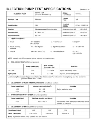

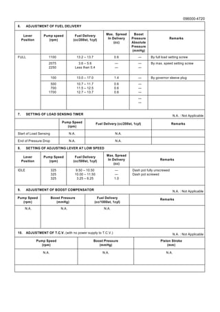
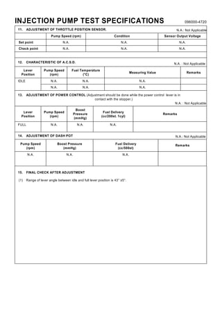

This document provides test specifications for an injection pump, including: 1. Pre-adjustment specifications for fuel delivery and pump speed at full load and high speed. 2. Adjustment procedures and specifications for internal pump pressure, overflow quantity, timer settings, fuel delivery levels, and load sensing timer. 3. The document notes that adjustments for boost compensator, throttle position sensor, ACSD, power control, and dash pot are not applicable.


