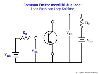
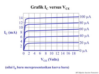
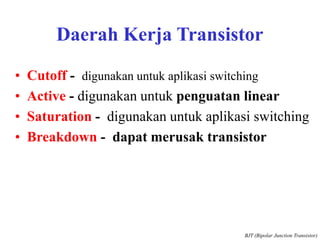
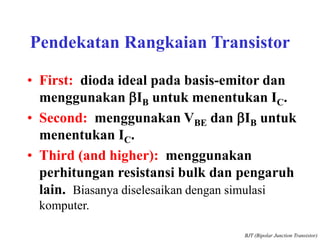
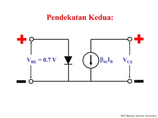
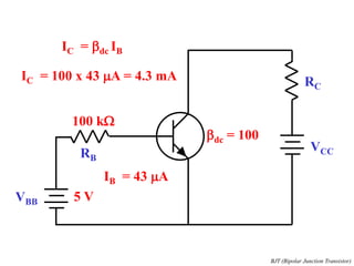
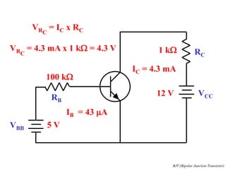
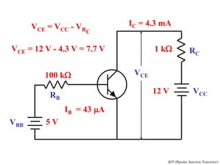
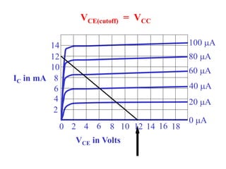
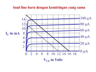
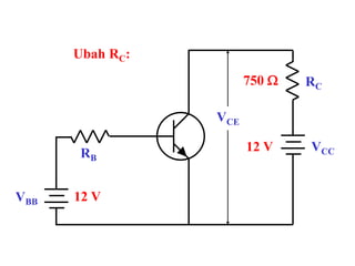
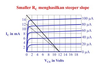
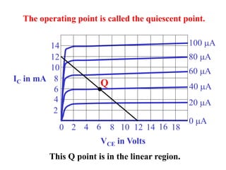
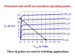
BJT
(Bipolar Junction Transistor)
Elektronika
(TKE 4012)
Eka Maulana
maulana.lecture.ub.ac.id
Pokok Bahasan
• Dasar Transistor
• Arus transistor
• Koneksi rangkaian
• Kurva transistor
• Pendekatan transistor
• Datasheet
• Load Line
• Titik Kerja
BJT (Bipolar Junction Transistor)
KOLEKTOR
(medium doping)
BASIS
(light doping)
EMITOR
(heavy doping)
N
N
BJT terdiri dari 3 bagian (dopping)
BJT (Bipolar Junction Transistor)
P
N
P
N
VCE
VCC
RC
RB
VBB
VBE
Saat transistor NPN dibias maju,
electron emiter menyebar ke basis dan kolektor
BJT (Bipolar Junction Transistor)
Aliran Arus Aliran Elektron
IC
IB
IE
IC
IB
IE
IE = IC + IB IC @ IE IB << IC
adc =
IC
IE
bdc =
IC
IB
BJT (Bipolar Junction Transistor)
VCE
VCC
RC
RB
VBB
VBE
Common Emitor memiliki dua loop:
Loop Basis dan Loop Kolektor
BJT (Bipolar Junction Transistor)
Notasi Subscript
• Ketika notasi subscript sama, maka
menyatakan sumber tegangan (VCC).
• Ketika notasi subscript sama,
menyatakan tegangan dua titik (VCE).
• Notasi single digunakan untuk
menyatakan tegangan node dengan
ground sebagai referensi (VC).
BJT (Bipolar Junction Transistor)
VCE
VCC
RC
RB
VBB
VBE
Rangkaian pada BASIS biasanya dianalisis
dengan pendekatan yang sama seperti digunakan pada dioda.
IB =
VBB - VBE
RB
BJT (Bipolar Junction Transistor)
0 2 4 6 8 10 12 14 16 18
2
4
6
8
10
12
14
VCE (Volts)
IC (mA)
Grafik IC versus VCE
20 mA
0 mA
100 mA
80 mA
60 mA
40 mA
(nilai IB baru merepresentasikan kurva baru)
BJT (Bipolar Junction Transistor)
Daerah Kerja Transistor
• Cutoff - digunakan untuk aplikasi switching
• Active - digunakan untuk penguatan linear
• Saturation - digunakan untuk aplikasi switching
• Breakdown - dapat merusak transistor
BJT (Bipolar Junction Transistor)
Pendekatan Rangkaian Transistor
• First: dioda ideal pada basis-emitor dan
menggunakan bIB untuk menentukan IC.
• Second: menggunakan VBE dan bIB untuk
menentukan IC.
• Third (and higher): menggunakan
perhitungan resistansi bulk dan pengaruh
lain. Biasanya diselesaikan dengan simulasi
komputer.
BJT (Bipolar Junction Transistor)
bdcIB VCE
VBE = 0.7 V
Pendekatan Kedua:
BJT (Bipolar Junction Transistor)
VCC
RC
RB
VBB
VBE = 0.7 V
IB =
VBB - VBE
RB
IB =
5 V - 0.7 V
100 kW
5 V
100 kW
= 43 mA
BJT (Bipolar Junction Transistor)
VCC
RC
RB
VBB 5 V
100 kW
IB = 43 mA
bdc = 100
IC = bdc IB
IC = 100 x 43 mA = 4.3 mA
BJT (Bipolar Junction Transistor)
VCC
RC
RB
VBB 5 V
100 kW
IB = 43 mA
IC = 4.3 mA
1 kW
12 V
VRC
= IC x RC
VRC
= 4.3 mA x 1 kW = 4.3 V
BJT (Bipolar Junction Transistor)
VCC
RC
RB
VBB 5 V
100 kW
IB = 43 mA
IC = 4.3 mA
1 kW
12 V
VCE = VCC - VRC
VCE
VCE = 12 V - 4.3 V = 7.7 V
BJT (Bipolar Junction Transistor)
Typical Breakdown Ratings
• VCBO = 60 V
• VCEO = 40 V
• VEBO = 6 V
• Note: these are reverse breakdown ratings
BJT (Bipolar Junction Transistor)
0
2
4
6
8
10
12
14
VCE (Volts)
IC (mA)
50
Grafik breakdown Colector
BJT (Bipolar Junction Transistor)
Typical Maximum Ratings
• IC = 200 mA dc
• PD = 250 mW (for TA = 60 o
C)
• PD = 350 mW (for TA = 25 o
C)
• PD = 1 W (for TC = 60 o
C)
BJT (Bipolar Junction Transistor)
Pembiasan BJT
(Bipolar Junction Transistor)
Elektronika
(TKE 4012)
Eka Maulana
maulana.lecture.ub.ac.id
VCC
RC
RB
VBB 12 V
1 kW
12 V
VCE = VCC - ICRC
VCE
0 2 4 6 8 10 12 14 16 18
2
4
6
8
10
12
14
VCE in Volts
IC in mA
20 mA
0 mA
100 mA
80 mA
60 mA
40 mA
IC =
VCC - VCE
RC
Persaman ini menghasilkan load line.
VCC
RC
RB
VBB 12 V
1 kW
12 V
Mental
short
IC =
12 V
1 kW
0 2 4 6 8 10 12 14 16 18
2
4
6
8
10
12
14
VCE in Volts
IC in mA
20 mA
0 mA
100 mA
80 mA
60 mA
40 mA
IC =
12 V
1 kW
= 12 mA Arus satutasi
VCC
RC
RB
VBB 12 V
1 kW
12 V
Mental
open
0 2 4 6 8 10 12 14 16 18
2
4
6
8
10
12
14
VCE in Volts
IC in mA
20 mA
0 mA
100 mA
80 mA
60 mA
40 mA
VCE(cutoff) = VCC
0 2 4 6 8 10 12 14 16 18
2
4
6
8
10
12
14
VCE in Volts
IC in mA
20 mA
0 mA
100 mA
80 mA
60 mA
40 mA
load line baru dengan kemiringan yang sama
VCC
RC
RB
VBB 12 V
1 kW
12 V
Ubah RC:
VCE
750 W
0 2 4 6 8 10 12 14 16 18
2
4
6
8
10
12
14
VCE in Volts
IC in mA
20 mA
0 mA
100 mA
80 mA
60 mA
40 mA
Smaller RC menghasilkan steeper slope
0 2 4 6 8 10 12 14 16 18
2
4
6
8
10
12
14
VCE in Volts
IC in mA
20 mA
0 mA
100 mA
80 mA
60 mA
40 mA
Rangkain dapat dioperasikan pada setiap titik pada load line
VCC
RC
RB = 283 kW
VBB 12 V
1 kW
12 V
IB =
VBB - VBE
RB
The operating point is determined by the base current.
IB =
12 V - 0.7 V
283 kW
= 40 mA
0 2 4 6 8 10 12 14 16 18
2
4
6
8
10
12
14
VCE in Volts
IC in mA
20 mA
0 mA
100 mA
80 mA
60 mA
40 mA
The operating point is called the quiescent point.
Q
This Q point is in the linear region.
0 2 4 6 8 10 12 14 16 18
2
4
6
8
10
12
14
VCE in Volts
IC in mA
20 mA
0 mA
100 mA
80 mA
60 mA
40 mA
Saturation and cutoff are non-linear operating points.
These Q points are used in switching applications.
Recognizing saturation
• Assume linear operation.
• Perform calculations for currents and
voltages.
• An impossible result means the
assumption is false.
• An impossible result indicates saturation.
Base bias
• The base current is established by VBB
and RB.
• The collector current is b times larger in
linear circuits.
• The transistor current gain will have a
large effect on the operating point.
• Transistor current gain is unpredictable.
VCC
RC
RE
VBB 5 V
1 kW
15 V
1 kW
2.2 kW
IE =
VBB - VBE
RE
= 1.95 mA
VC = 15 V - (1.95 mA)(1 kW) = 13.1 V
Emitter bias:
VCE = 13.1 V - 4.3 V = 8.8 V
IC @ IE

06-BJT-Bipolar-Junction-Transistor.pdf

  • 1.
    BJT (Bipolar Junction Transistor) Elektronika (TKE4012) Eka Maulana maulana.lecture.ub.ac.id
  • 2.
    Pokok Bahasan • DasarTransistor • Arus transistor • Koneksi rangkaian • Kurva transistor • Pendekatan transistor • Datasheet • Load Line • Titik Kerja BJT (Bipolar Junction Transistor)
  • 3.
    KOLEKTOR (medium doping) BASIS (light doping) EMITOR (heavydoping) N N BJT terdiri dari 3 bagian (dopping) BJT (Bipolar Junction Transistor) P
  • 4.
    N P N VCE VCC RC RB VBB VBE Saat transistor NPNdibias maju, electron emiter menyebar ke basis dan kolektor BJT (Bipolar Junction Transistor)
  • 5.
    Aliran Arus AliranElektron IC IB IE IC IB IE IE = IC + IB IC @ IE IB << IC adc = IC IE bdc = IC IB BJT (Bipolar Junction Transistor)
  • 6.
    VCE VCC RC RB VBB VBE Common Emitor memilikidua loop: Loop Basis dan Loop Kolektor BJT (Bipolar Junction Transistor)
  • 7.
    Notasi Subscript • Ketikanotasi subscript sama, maka menyatakan sumber tegangan (VCC). • Ketika notasi subscript sama, menyatakan tegangan dua titik (VCE). • Notasi single digunakan untuk menyatakan tegangan node dengan ground sebagai referensi (VC). BJT (Bipolar Junction Transistor)
  • 8.
    VCE VCC RC RB VBB VBE Rangkaian pada BASISbiasanya dianalisis dengan pendekatan yang sama seperti digunakan pada dioda. IB = VBB - VBE RB BJT (Bipolar Junction Transistor)
  • 9.
    0 2 46 8 10 12 14 16 18 2 4 6 8 10 12 14 VCE (Volts) IC (mA) Grafik IC versus VCE 20 mA 0 mA 100 mA 80 mA 60 mA 40 mA (nilai IB baru merepresentasikan kurva baru) BJT (Bipolar Junction Transistor)
  • 10.
    Daerah Kerja Transistor •Cutoff - digunakan untuk aplikasi switching • Active - digunakan untuk penguatan linear • Saturation - digunakan untuk aplikasi switching • Breakdown - dapat merusak transistor BJT (Bipolar Junction Transistor)
  • 11.
    Pendekatan Rangkaian Transistor •First: dioda ideal pada basis-emitor dan menggunakan bIB untuk menentukan IC. • Second: menggunakan VBE dan bIB untuk menentukan IC. • Third (and higher): menggunakan perhitungan resistansi bulk dan pengaruh lain. Biasanya diselesaikan dengan simulasi komputer. BJT (Bipolar Junction Transistor)
  • 12.
    bdcIB VCE VBE =0.7 V Pendekatan Kedua: BJT (Bipolar Junction Transistor)
  • 13.
    VCC RC RB VBB VBE = 0.7V IB = VBB - VBE RB IB = 5 V - 0.7 V 100 kW 5 V 100 kW = 43 mA BJT (Bipolar Junction Transistor)
  • 14.
    VCC RC RB VBB 5 V 100kW IB = 43 mA bdc = 100 IC = bdc IB IC = 100 x 43 mA = 4.3 mA BJT (Bipolar Junction Transistor)
  • 15.
    VCC RC RB VBB 5 V 100kW IB = 43 mA IC = 4.3 mA 1 kW 12 V VRC = IC x RC VRC = 4.3 mA x 1 kW = 4.3 V BJT (Bipolar Junction Transistor)
  • 16.
    VCC RC RB VBB 5 V 100kW IB = 43 mA IC = 4.3 mA 1 kW 12 V VCE = VCC - VRC VCE VCE = 12 V - 4.3 V = 7.7 V BJT (Bipolar Junction Transistor)
  • 17.
    Typical Breakdown Ratings •VCBO = 60 V • VCEO = 40 V • VEBO = 6 V • Note: these are reverse breakdown ratings BJT (Bipolar Junction Transistor)
  • 18.
    0 2 4 6 8 10 12 14 VCE (Volts) IC (mA) 50 Grafikbreakdown Colector BJT (Bipolar Junction Transistor)
  • 19.
    Typical Maximum Ratings •IC = 200 mA dc • PD = 250 mW (for TA = 60 o C) • PD = 350 mW (for TA = 25 o C) • PD = 1 W (for TC = 60 o C) BJT (Bipolar Junction Transistor)
  • 20.
    Pembiasan BJT (Bipolar JunctionTransistor) Elektronika (TKE 4012) Eka Maulana maulana.lecture.ub.ac.id
  • 21.
    VCC RC RB VBB 12 V 1kW 12 V VCE = VCC - ICRC VCE
  • 22.
    0 2 46 8 10 12 14 16 18 2 4 6 8 10 12 14 VCE in Volts IC in mA 20 mA 0 mA 100 mA 80 mA 60 mA 40 mA IC = VCC - VCE RC Persaman ini menghasilkan load line.
  • 23.
    VCC RC RB VBB 12 V 1kW 12 V Mental short IC = 12 V 1 kW
  • 24.
    0 2 46 8 10 12 14 16 18 2 4 6 8 10 12 14 VCE in Volts IC in mA 20 mA 0 mA 100 mA 80 mA 60 mA 40 mA IC = 12 V 1 kW = 12 mA Arus satutasi
  • 25.
    VCC RC RB VBB 12 V 1kW 12 V Mental open
  • 26.
    0 2 46 8 10 12 14 16 18 2 4 6 8 10 12 14 VCE in Volts IC in mA 20 mA 0 mA 100 mA 80 mA 60 mA 40 mA VCE(cutoff) = VCC
  • 27.
    0 2 46 8 10 12 14 16 18 2 4 6 8 10 12 14 VCE in Volts IC in mA 20 mA 0 mA 100 mA 80 mA 60 mA 40 mA load line baru dengan kemiringan yang sama
  • 28.
    VCC RC RB VBB 12 V 1kW 12 V Ubah RC: VCE 750 W
  • 29.
    0 2 46 8 10 12 14 16 18 2 4 6 8 10 12 14 VCE in Volts IC in mA 20 mA 0 mA 100 mA 80 mA 60 mA 40 mA Smaller RC menghasilkan steeper slope
  • 30.
    0 2 46 8 10 12 14 16 18 2 4 6 8 10 12 14 VCE in Volts IC in mA 20 mA 0 mA 100 mA 80 mA 60 mA 40 mA Rangkain dapat dioperasikan pada setiap titik pada load line
  • 31.
    VCC RC RB = 283kW VBB 12 V 1 kW 12 V IB = VBB - VBE RB The operating point is determined by the base current. IB = 12 V - 0.7 V 283 kW = 40 mA
  • 32.
    0 2 46 8 10 12 14 16 18 2 4 6 8 10 12 14 VCE in Volts IC in mA 20 mA 0 mA 100 mA 80 mA 60 mA 40 mA The operating point is called the quiescent point. Q This Q point is in the linear region.
  • 33.
    0 2 46 8 10 12 14 16 18 2 4 6 8 10 12 14 VCE in Volts IC in mA 20 mA 0 mA 100 mA 80 mA 60 mA 40 mA Saturation and cutoff are non-linear operating points. These Q points are used in switching applications.
  • 34.
    Recognizing saturation • Assumelinear operation. • Perform calculations for currents and voltages. • An impossible result means the assumption is false. • An impossible result indicates saturation.
  • 35.
    Base bias • Thebase current is established by VBB and RB. • The collector current is b times larger in linear circuits. • The transistor current gain will have a large effect on the operating point. • Transistor current gain is unpredictable.
  • 36.
    VCC RC RE VBB 5 V 1kW 15 V 1 kW 2.2 kW IE = VBB - VBE RE = 1.95 mA VC = 15 V - (1.95 mA)(1 kW) = 13.1 V Emitter bias: VCE = 13.1 V - 4.3 V = 8.8 V IC @ IE