2. -2
This manual contains maintenance and repair procedures for the
2007 INFINITI QX56.
In order to assure your safety and the efficient functioning of the vehicle,
this manual should be read thoroughly. It is especially important that the
PRECAUTIONS in the GI section be completely understood before starting
any repair task.
All information in this manual is based on the latest product information
at the time of publication. The right is reserved to make changes in specifi-
cations and methods at any time without notice.
IMPORTANT SAFETY NOTICE
The proper performance of service is essential for both the safety of
the technician and the efficient functioning of the vehicle.
The service methods in this Service Manual are described in such a
manner that the service may be performed safely and accurately.
Service varies with the procedures used, the skills of the technician
and the tools and parts available. Accordingly, anyone using service
procedures, tools or parts which are not specifically recommended
by NISSAN must first be completely satisfied that neither personal
safety nor the vehicle’s safety will be jeopardized by the service
method selected.
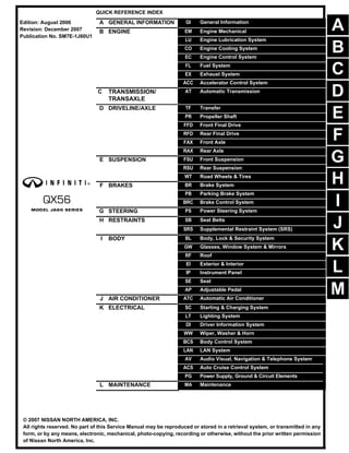
3. QUICK REFERENCE CHART: QX56 2007
QUICK REFERENCE CHART: QX56 PFP:00000
Engine Tune-Up Data ELS0028Z
Cylinder arrangement V-8
Displacement cm3
(cu in) 5,552 (338.80)
Bore and stroke mm (in) 98 x 92 (3.86 x 3.62)
Valve arrangement DOHC
Firing order 1-8-7-3-6-5-4-2
Number of piston rings
Compression 2
Oil 1
Number of main bearings 5
Compression ratio 9.8:1
Compression pressure
kPa (kg/cm2
, psi)/rpm
Standard 1,520 (15.5, 220)/200
Minimum 1,324 (13.5, 192)/200
Differential limit between cylinders 98 (1.0, 14)/200
Cylinder number
Valve timing
Unit: degree
a b c d e f
244° 232° -8° 60° 10° 54°
SEM957C
PBIC0187E
4. 2007
QUICK REFERENCE CHART: QX56
Drive Belt Deflection and Tension
Spark Plug (Platinum Tipped)
Front Wheel Alignment (Unladen*1 ) ELS00290
*1: Fuel, radiator coolant and engine oil full. Spare tire, jack, hand tools and mats in designated positions.
*2: Target value 37° 31′ (37.52°)
*3: Target value 33° 59′ (33.98°)
*4: Target value 37° 44′ (37.73°)
*5: Target value 33° 29′ (33.48°)
Tension of drive belts Auto adjustment by auto tensioner
Make NGK
Standard type DIFR5A-11
Gap (nominal) 1.1 mm (0.043 in)
Drive type 2WD 4WD
Camber
Degree minute (decimal degree)
Minimum -0° 51′ (-0.85°) -0° 33′ (-0.55°)
Nominal -0° 6′ (-0.10°) 0° 12′ (0.20°)
Maximum 0° 39′ (0.65°) 0° 57′ (0.95°)
Cross camber 0° 45′ (0.75°) or less 0° 45′ (0.75°) or less
Caster
Degree minute (decimal degree)
Minimum 3° 15′ (3.25°) 2° 45′ (2.75°)
Nominal 4° 0′ (4.00°) 3° 30′ (3.50°)
Maximum 4° 45′ (4.75°) 4° 15′ (4.25°)
Cross caster 0° 45′ (0.75°) or less 0° 45′ (0.75°) or less
Kingpin inclination
Degree minute (decimal degree)
13° 32′ (13.53°) 13°13′ (13.22°)
Total toe-in
Distance (A − B)
Minimum 1.8 mm (0.07 in) 1.8 mm (0.07 in)
Nominal 2.8 mm (0.11 in) 2.8 mm (0.11 in)
Maximum 3.8 mm (0.15 in) 3.8 mm (0.15 in)
Angle (left side and right side)
Degree minute (decimal degree)
Minimum 0° 3′ (0.05°) 0° 3′ (0.05°)
Nominal 0° 5′ (0.08°) 0° 5′ (0.08°)
Maximum 0° 7′ (0.12°) 0° 7′ (0.12°)
Wheel turning angle
(full turn)
Inside
Degree minute (decimal degree)
34° 31′ – 38° 31′ *2
(34.52° – 38.52°)
34° 44′ – 38° 44′ *4
(34.73° – 38.73°)
Outside
Degree minute (decimal degree)
30° 59′ – 34° 59′ *3
(30.98° – 34.98°)
30° 29′ – 34° 29′ *5
(30.48° – 34.48°)
SFA234AC
5. QUICK REFERENCE CHART: QX56
2007
Rear Wheel Alignment ELS00291
Brake ELS00292
Unit: mm (in)
Camber
Degree minute (decimal degree)
Minimum 0° 0′ (0°)
Nominal - 0° 30′ (-0.5°)
Maximum - 1° 0′ (-1.0°)
Cross camber 0° 45′ (0.75°)
Toe-in
Distance (A - B)
Minimum 0 mm (0 in)
Nominal 3.3 mm (0.130 in)
Maximum 6.6 mm (0.260 in)
Cross toe 2 mm (0.079 in)
Angle (left, right)
Degree minute (decimal degree)
Minimum 0° 0′ (0°)
Nominal 0° 7′ (0.11°)
Maximum 0° 14′ (0.22°)
Cross toe 0° 8′ (0.14°)
SFA234AC
Front brake Brake model AD41VA
Rotor outer diameter × thickness 350 x 30 (13.78 x 1.18)
Pad Length × width × thickness 151.6 x 56.5 x 12.0 (5.97 x 2.22 x 0.476)
Cylinder bore diameter 51 (2.01)
Rear brake Brake model AD14VE
Rotor outer diameter × thickness 320 x 14 (12.60 x 0.55)
Pad Length × width × thickness 83.0 x 33.0 x 8.5 (3.268 x 1.299 x 0.335)
Cylinder bore diameter 48 (1.89)
Control valve Valve model Electric brake force distribution
Brake booster Booster model C215T
Diaphragm diameter 215 (8.46)
Recommended brake fluid Refer to ! Hyper-link Error !
6. 2007
QUICK REFERENCE CHART: QX56
Disc Brake - Repair Limits ELS00293
Unit: mm (in)
Brake Pedal ELS00294
Unit: mm (in)
Front brake model AD41VA
Brake pad
Standard thickness (new) 12.0 (0.476)
Repair limit thickness 1.0 (0.039)
Disc rotor
Standard thickness (new) 30 (1.18)
Repair limit thickness 28.5 (1.122)
Maximum uneven wear (measured at 8 positions) 0.015 (0.0006)
Runout limit (with it attached to the vehicle) 0.03 (0.001)
Rear brake model AD14VE
Brake pad
Standard thickness (new) 12.13 mm (0.478 in)
Repair limit thickness 1.0 mm (0.039 in)
Disc rotor
Standard thickness (new) 14.0 mm (0.551 in)
Repair limit thickness 12.0 mm (0.472 in)
Maximum uneven wear (measured at 8 positions) 0.015 mm (0.0006 in)
Runout limit (with it attached to the vehicle) 0.05 mm (0.002 in)
Free height "H" 182.3 - 192.3 mm (7.18 - 7.57 in)
Depressed pedal height "D" [under a force of 490 N (50 kg-f, 110 lb-f) with engine
running]
More than 90.3 mm (3.55 in)
Clearance between pedal stopper and threaded end of stop lamp switch and
ASCD switch "C1 " or “C2 ”
0.74 - 1.96 mm (0.029 - 0.077 in)
Pedal play "A" 3 - 11 mm (0.12 - 0.43 in)
WFIA0160E
7. QUICK REFERENCE CHART: QX56
2007
Refill Capacities ELS00295
Description
Capacity (Approximate)
Metric US measure Imp measure
Fuel 105.8 28 gal 23 1/4 gal
Engine oil
(drain and refill)
With oil filter change 6.2 6 1/2 qt 5 1/2 qt
Without oil filter change 5.9 6 1/4 qt 5 1/4 qt
Dry engine (engine overhaul) 7.6 8 qt 6 3/4 qt
Cooling system With reservoir at MAX level 14.4 3 3/4 gal 3 1/8 gal
Automatic transmission fluid (ATF) 10.6 11 1/4 qt 9 3/8 qt
Rear final drive oil 1.75 3 3/4 pt 3 1/8 pt
Transfer fluid 3.0 3 1/8 qt 2 5/8 qt
Front final drive oil 1.6 3 3/8 pt 2 7/8 pt
Power steering fluid (PSF) 1.0 2 1/8 pt 1 3/4 pt
Windshield washer fluid 4.5 1 1/4 gal 1 gal
Air conditioning system refrigerant 1.08 ± 0.05 kg 2.38 ± 0.11 lb 2.38 ± 0.11 lb
Air conditioning system lubricants 290 m 9.8 fl oz 10.2 fl oz
8. GI-1
GENERAL INFORMATION
C
D
E
F
G
H
I
J
K
L
M
B
GI
SECTION GI
N
O
P
CONTENTS
GENERAL INFORMATION
SERVICE INFORMATION ........................
.... 2
PRECAUTIONS ..............................................
..... 2
Description ..........................................................
......2
Precaution for Supplemental Restraint System
(SRS) "AIR BAG" and "SEAT BELT PRE-TEN-
SIONER" .............................................................
......2
Precaution for NVIS/IVIS (NISSAN/INFINITI VE-
HICLE IMMOBILIZER SYSTEM - NATS) (If
Equipped) ............................................................
......2
General Precaution .............................................
......3
Precaution for Three Way Catalyst .....................
......4
Precaution for Fuel (Unleaded Premium Gasoline
Required) ............................................................
......4
Precaution for Multiport Fuel Injection System or
Engine Control System .......................................
......5
Precaution for Hoses ...........................................
......5
Precaution for Engine Oils ..................................
......6
Precaution for Air Conditioning ...........................
......6
HOW TO USE THIS MANUAL .......................
..... 7
Description ..........................................................
......7
Terms ..................................................................
......7
Units ....................................................................
......7
Relation between Illustrations and Descriptions .
......7
Contents ..............................................................
......8
Component ..........................................................
......8
How to Follow Trouble Diagnosis ........................
......9
How to Read Wiring Diagram ..............................
....13
Abbreviations ......................................................
....20
SERVICE INFORMATION FOR ELECTRICAL
INCIDENT .......................................................
....22
How to Check Terminal .......................................
....22
How to Perform Efficient Diagnosis for an Electri-
cal Incident ..........................................................
....25
Control Units and Electrical Parts ........................
....32
CONSULT-II CHECKING SYSTEM ..................35
Description ...........................................................
....35
Function and System Application ........................
....35
Nickel Metal Hydride Battery Replacement .........
....36
Checking Equipment ...........................................
....36
CONSULT-II Start Procedure ..............................
....36
CONSULT-II Data Link Connector (DLC) Circuit .
....38
LIFTING POINT .................................................40
Pantograph Jack ..................................................
....40
Garage Jack and Safety Stand ............................
....40
2-Pole Lift ............................................................
....40
TOW TRUCK TOWING .....................................42
Tow Truck Towing ...............................................
....42
Vehicle Recovery (Freeing a stuck vehicle) ........
....43
TIGHTENING TORQUE OF STANDARD
BOLTS ...............................................................44
Tightening Torque Table .....................................
....44
RECOMMENDED CHEMICAL PRODUCTS
AND SEALANTS ...............................................45
Recommended Chemical Product and Sealant ...
....45
IDENTIFICATION INFORMATION ....................46
Model Variation ....................................................
....46
Identification Number ...........................................
....47
Dimensions ..........................................................
....48
Wheels & Tires ....................................................
....48
TERMINOLOGY ................................................50
SAE J1930 Terminology List ...............................
....50
Revision: December 2007 2007 QX56
9. Thank you very much for
your reading. Please Click
Here. Then Get COMPLETE
MANUAL. NO WAITING
NOTE:
If there is no response to
click on the link above,
please download the PDF
document first and then
click on it.
10. GI-2
< SERVICE INFORMATION >
PRECAUTIONS
SERVICE INFORMATION
PRECAUTIONS
Description INFOID:0000000003531468
Observe the following precautions to ensure safe and proper servicing. These precautions are not
described in each individual section.
Precaution for Supplemental Restraint System (SRS) "AIR BAG" and "SEAT BELT
PRE-TENSIONER" INFOID:0000000003531469
The Supplemental Restraint System such as “AIR BAG” and “SEAT BELT PRE-TENSIONER”, used along
with a front seat belt, helps to reduce the risk or severity of injury to the driver and front passenger for certain
types of collision. This system includes seat belt switch inputs and dual stage front air bag modules. The SRS
system uses the seat belt switches to determine the front air bag deployment, and may only deploy one front
air bag, depending on the severity of a collision and whether the front occupants are belted or unbelted.
Information necessary to service the system safely is included in the SRS and SB section of this Service Man-
ual.
WARNING:
• To avoid rendering the SRS inoperative, which could increase the risk of personal injury or death in
the event of a collision which would result in air bag inflation, all maintenance must be performed by
an authorized NISSAN/INFINITI dealer.
• Improper maintenance, including incorrect removal and installation of the SRS, can lead to personal
injury caused by unintentional activation of the system. For removal of Spiral Cable and Air Bag
Module, see the SRS section.
• Do not use electrical test equipment on any circuit related to the SRS unless instructed to in this
Service Manual. SRS wiring harnesses can be identified by yellow and/or orange harnesses or har-
ness connectors.
Precaution for NVIS/IVIS (NISSAN/INFINITI VEHICLE IMMOBILIZER SYSTEM -
NATS) (If Equipped) INFOID:0000000003531470
NVIS/IVIS (NATS) will immobilize the engine if someone tries to start it without the registered key of NVIS/IVIS
(NATS).
Both of the originally supplied ignition key IDs have been NVIS/IVIS (NATS) registered.
The security indicator is located on the instrument panel. The indicator blinks when the immobilizer system is
functioning.
Therefore, NVIS/IVIS (NATS) warns outsiders that the vehicle is equipped with the anti-theft system.
• When NVIS/IVIS (NATS) detects trouble, the security indicator lamp lights up while ignition switch is in "ON"
position.
This lighting up indicates that the anti-theft is not functioning, so prompt service is required.
• When servicing NVIS/IVIS (NATS) (trouble diagnoses, system initialization and additional registration of
other NVIS/IVIS (NATS) ignition key IDs), CONSULT-II hardware and CONSULT-II NVIS/IVIS (NATS) soft-
ware is necessary.
Regarding the procedures of NVIS/IVIS (NATS) initialization and NVIS/IVIS (NATS) ignition key ID registra-
tion, refer to CONSULT-II operation manual, NVIS/IVIS (NATS).
Therefore, CONSULT-II NVIS/IVIS (NATS) software (program card and operation manual) must be kept
strictly confidential to maintain the integrity of the anti-theft function.
• When servicing NVIS/IVIS (NATS) (trouble diagnoses, system initialization and additional registration of
other NVIS/IVIS (NATS) ignition key IDs), it may be necessary to re-register original key identification.
Therefore, be sure to receive all keys from vehicle owner. A maximum of four or five key IDs can be regis-
tered into NVIS/IVIS (NATS).
• When failing to start the engine first time using the key of NVIS/IVIS (NATS), start as follows.
1. Leave the ignition key in "ON" position for approximately 5 seconds.
2. Turn ignition key to "OFF" or "LOCK" position and wait approximately 5 seconds.
3. Repeat step 1 and 2 again.
4. Restart the engine while keeping the key separate from any others on key-chain.
Revision: December 2007 2007 QX56
11. PRECAUTIONS
GI-3
< SERVICE INFORMATION >
C
D
E
F
G
H
I
J
K
L
M
B
GI
N
O
P
General Precaution INFOID:0000000003531471
• Do not operate the engine for an extended period of time without
proper exhaust ventilation.
Keep the work area well ventilated and free of any flammable
materials. Special care should be taken when handling any flam-
mable or poisonous materials, such as gasoline, refrigerant gas,
etc. When working in a pit or other enclosed area, be sure to prop-
erly ventilate the area before working with hazardous materials.
Do not smoke while working on the vehicle.
• Before jacking up the vehicle, apply wheel chocks or other tire
blocks to the wheels to prevent the vehicle from moving. After jack-
ing up the vehicle, support the vehicle weight with safety stands at
the points designated for proper lifting before working on the vehi-
cle.
These operations should be done on a level surface.
• When removing a heavy component such as the engine or tran-
saxle/transmission, be careful not to lose your balance and drop
them. Also, do not allow them to strike adjacent parts, especially
the brake tubes and master cylinder.
• Before starting repairs which do not require battery power:
Turn off ignition switch.
Disconnect the negative battery terminal.
• If the battery terminals are disconnected, recorded memory of
radio and each control unit is erased.
• Battery posts, terminals and related accessories contain lead and
lead compounds. Wash hands after handling.
• To prevent serious burns:
Avoid contact with hot metal parts.
Do not remove the radiator cap when the engine is hot.
• Dispose of or recycle drained oil or the solvent used for cleaning
parts in an appropriate manner.
• Do not attempt to top off the fuel tank after the fuel pump nozzle
shuts off automatically.
Continued refueling may cause fuel overflow, resulting in fuel spray
and possibly a fire.
• Clean all disassembled parts in the designated liquid or solvent
prior to inspection or assembly.
• Replace oil seals, gaskets, packings, O-rings, locking washers,
cotter pins, self-locking nuts, etc. with new ones.
• Replace inner and outer races of tapered roller bearings and needle bearings as a set.
• Arrange the disassembled parts in accordance with their assembled locations and sequence.
• Do not touch the terminals of electrical components which use microcomputers (such as ECM).
Static electricity may damage internal electronic components.
• After disconnecting vacuum or air hoses, attach a tag to indicate the proper connection.
• Use only the fluids and lubricants specified in this manual.
• Use approved bonding agent, sealants or their equivalents when required.
SGI285
SGI231
SEF289H
SGI233
Revision: December 2007 2007 QX56
12. GI-4
< SERVICE INFORMATION >
PRECAUTIONS
• Use hand tools, power tools (disassembly only) and recommended
special tools where specified for safe and efficient service repairs.
• When repairing the fuel, oil, water, vacuum or exhaust systems,
check all affected lines for leaks.
• Before servicing the vehicle:
Protect fenders, upholstery and carpeting with appropriate covers.
Take caution that keys, buckles or buttons do not scratch paint.
WARNING:
To prevent ECM from storing the diagnostic trouble codes, do not carelessly disconnect the harness
connectors which are related to the engine control system and TCM (transmission control module)
system. The connectors should be disconnected only when working according to the WORK FLOW of
TROUBLE DIAGNOSES in EC and AT sections.
Precaution for Three Way Catalyst INFOID:0000000003531472
If a large amount of unburned fuel flows into the catalyst, the catalyst temperature will be excessively high. To
prevent this, follow the instructions.
• Use unleaded gasoline only. Leaded gasoline will seriously damage the three way catalyst.
• When checking for ignition spark or measuring engine compression, make tests quickly and only when nec-
essary.
• Do not run engine when the fuel tank level is low, otherwise the engine may misfire, causing damage to the
catalyst.
Do not place the vehicle on flammable material. Keep flammable material off the exhaust pipe and the three
way catalyst.
Precaution for Fuel (Unleaded Premium Gasoline Required) INFOID:0000000003531473
Use unleaded premium gasoline with an octane rating of at least 91 AKI (Anti-Knock Index) number (Research
octane number 96).
If unleaded premium gasoline is not available, unleaded regular gasoline with an octane rating of at least 87
AKI number (Research octane number 91) can be used, but only under the following precautions:
• have the fuel tank filled only partially with unleaded regular gasoline, and fill up with unleaded premium gas-
oline as soon as possible.
• avoid full throttle driving and abrupt acceleration.
However, for maximum vehicle performance, the use of unleaded premium gasoline is recommended.
CAUTION:
Do not use leaded gasoline. Using leaded gasoline will damage the three way catalyst. Do not use E-85
fuel (85% fuel ethanol, 15% unleaded gasoline) unless the vehicle is specifically designed for E-85 fuel
(i.e. Flexible Fuel Vehicle - FFV models). Using a fuel other than that specified could adversely affect
the emission control devices and systems, and could also affect the warranty coverage validity.
PBIC0190E
SGI234
Revision: December 2007 2007 QX56
13. PRECAUTIONS
GI-5
< SERVICE INFORMATION >
C
D
E
F
G
H
I
J
K
L
M
B
GI
N
O
P
Precaution for Multiport Fuel Injection System or Engine Control System INFOID:0000000003531474
• Before connecting or disconnecting any harness connector for the
multiport fuel injection system or ECM:
Turn ignition switch to “OFF” position.
Disconnect negative battery terminal.
Otherwise, there may be damage to ECM.
• Before disconnecting pressurized fuel line from fuel pump to injec-
tors, be sure to release fuel pressure.
• Be careful not to jar components such as ECM and mass air flow
sensor.
Precaution for Hoses INFOID:0000000003531475
HOSE REMOVAL and INSTALLATION
• To prevent damage to rubber hose, do not pry off rubber hose with
tapered tool or screwdriver.
• To reinstall the rubber hose securely, make sure of hose insertion
length and clamp orientation. (If tube is equipped with hose stop-
per, insert rubber hose into tube until it butts up against hose stop-
per.)
HOSE CLAMPING
• If old rubber hose is re-used, install hose clamp in its original posi-
tion (at the indentation where the old clamp was). If there is a trace
of tube bulging left on the old rubber hose, align rubber hose at
that position.
• Discard old clamps; replace with new ones.
SGI787
SMA019D
SMA020D
SMA021D
Revision: December 2007 2007 QX56
14. GI-6
< SERVICE INFORMATION >
PRECAUTIONS
• After installing leaf spring clamps, apply force to them in the direc-
tion of the arrow, tightening rubber hose equally all around.
Precaution for Engine Oils INFOID:0000000003531476
Prolonged and repeated contact with used engine oil may cause skin cancer. Try to avoid direct skin contact
with used oil.
If skin contact is made, wash thoroughly with soap or hand cleaner as soon as possible.
HEALTH PROTECTION PRECAUTIONS
• Avoid prolonged and repeated contact with oils, particularly used engine oils.
• Wear protective clothing, including impervious gloves where practicable.
• Do not put oily rags in pockets.
• Avoid contaminating clothes, particularly underpants, with oil.
• Heavily soiled clothing and oil-impregnated footwear should not be worn. Overalls must be cleaned regu-
larly.
• First aid treatment should be obtained immediately for open cuts and wounds.
• Use barrier creams, applying them before each work period, to help the removal of oil from the skin.
• Wash with soap and water to ensure all oil is removed (skin cleansers and nail brushes will help). Prepara-
tions containing lanolin replace the natural skin oils which have been removed.
• Do not use gasoline, kerosene, diesel fuel, gas oil, thinners or solvents for cleaning skin.
• If skin disorders develop, obtain medical advice without delay.
• Where practical, degrease components prior to handling.
• Where there is a risk of eye contact, eye protection should be worn, for example, chemical goggles or face
shields; in addition an eye wash facility should be provided.
Precaution for Air Conditioning INFOID:0000000003531477
Use an approved refrigerant recovery unit any time the air conditioning system must be discharged. Refer to
ATC-150, "HFC-134a (R-134a) Service Procedure" for specific instructions.
SMA022D
Revision: December 2007 2007 QX56