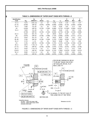
SURFACE                                                      J744
                                                                                                                                                                 REV.
                                                                                                                                                                JUN96
                                                                         VEHICLE
    400 Commonwealth Drive, Warrendale, PA 15096-0001
                                                                         STANDARD                                             Issued              1952-01
                                                                                                                              Revised             1996-06

                                                                                                                              Superseding J744 NOV95
                                                   Submitted for recognition as an American National Standard


                                 HYDRAULIC PUMP AND MOTOR MOUNTING AND DRIVE DIMENSIONS


   1.       Scope—This SAE Standard applies to hydraulic pumps and motors used on off-road self-propelled work
            machines as described in categories 1 through 5 of SAE J1116 JUN86.

   1.1      Purpose—To provide a progression of standard mounting flanges and shafts that are dimensionally
            compatible.

   2.       References

   2.1      Applicable Publications—The following publications form a part of the specification to the extent specified
            herein. Unless otherwise indicated the lastest revision of SAE publications shall apply.

   2.1.1       SAE PUBLICATIONS—Available from SAE, 400 Commonwealth Drive, Warrendale, PA 15096-0001.

                  SAE J390—Dual Dimensioning
                  SAE J1116 JUN86—Categories of Off-Road Self-Propelled Work Machines
                  SAE TSB 003—Rules for SAE Use of SI (Metric) Units

   2.1.2       ANSI PUBLICATIONS—Available from ANSI, 11 West 42nd Street, New York, NY 10036-8002.

                  ANSI B1.1—Screw Threads
                  ANSI B92.1-1970—Involute Splines and Inspection

   3.       Units

   3.1      The International System of Units (SI) is used herein in accordance with Reference 7.1.

   3.2      Customary U.S. units are given for information purposes, and these appear in parentheses next to their SI
            counterpart.

   4.       Identification Code

   4.1      Flange identification codes are found in Table 1.

   4.1.1       The number preceding the dash (—) is an approximation, in millimeters, of the mounting flange pilot
               diameter.


SAE Technical Standards Board Rules provide that: “This report is published by SAE to advance the state of technical and engineering sciences. The use of this report is entirely
voluntary, and its applicability and suitability for any particular use, including any patent infringement arising therefrom, is the sole responsibility of the user.”

SAE reviews each technical report at least every five years at which time it may be reaffirmed, revised, or cancelled. SAE invites your written comments and suggestions.

                                          QUESTIONS REGARDING THIS DOCUMENT: (724) 772-8512 FAX: (724) 776-0243
                                                TO PLACE A DOCUMENT ORDER; (724) 776-4970 FAX: (724) 776-0790
                                                                   http:www.sae.org
Copyright 1996 Society of Automotive Engineers, Inc.
All rights reserved.                                                                                                                                            Printed in U.S.A.
SAE J744 Revised JUN96

4.1.2     The number following the dash (—) states the number of mounting holes in the flange.


                 TABLE 1—DIMENSIONS OF 2 AND 4 BOLT PUMP AND MOTOR MOUNTING FLANGES
                  Pilot     Pilot      Pilot       Pilot   2 Bolt                                  2 Bolt                       4 Bolt
                 Dimen-    Dimen-     Dimen-      Dimen-   Type                          2 Bolt    Type               4 Bolt    Type
     Identi-      sions     sions      sions       sions     B       2 Bolt    2 Bolt    Type        P1     4 Bolt    Type        P2
    fication        A         W          X           Y      Cast     Type      Type        M        Cast    Type        R        Cast
      Code       Noted     Noted        Min         Max     Dim.       J         K       Noted      Dim.      S       Noted      Dim.
        50—(1)    50.80      6.4          —        0.8       64       14       82.6       10.3      10        —         —        —
        (A—A)    (2.000)    (0.250)       —       (0.03)   (2.50)    (0.56)   (3.250)    (0.406)   (0.38)     —         —        —
        82—(1)    82.55      6.4          —        0.8       95       18       106.4      11.1      12        —         —        —
         (A)     (3.250)    (0.250)       —       (0.03)   (3.75)    (0.72)   (4.188)    (0.438)   (0.47)     —         —        —
    101—(1)      101.60      9.7          51       1.5      120       25       146.0      14.3      14       89.8      14.3      14
         (B)     (4.000)    (0.380)      (2.00)   (0.06)   (4.75)    (0.99)   (5.750)    (0.562)   (0.56)   (3.536)   (0.562)   (0.56)
    127—(1)      127.00      12.7         64       1.5      148       31       181.0      17.5      16      114.5      14.3      16
         (C)     (5.000)    (0.500)      (2.50)   (0.06)   (5.81)    (1.22)   (7.125)    (0.688)   (0.62)   (4.508)   (0.562)   (0.62)
    152—(1)      152.40      12.7         70       1.5      200       40       228.6      20.6      19      161.6      20.6      19
         (D)     (6.000)    (0.500)      (2.75)   (0.06)   (7.88)    (1.55)   (9.000)    (0.812)   (0.75)   (6.364)   (0.812)   (0.75)
    165—(1)      165.10      15.9         70       2.3      270       55       317.5      27.0      25      224.5      20.6      19
         (E)     (6.500)    (0.625)      (2.75)   (0.09)   (10.62)   (2.15)   (12.500)   (1.062)   (1.00)   (8.839)   (0.812)   (0.75)
    177—(1)      177.80      15.9         70       2.3      300       60       350.0      27.0      25      247.5      27.0      25
         (F)     (7.000)    (0.625)      (2.75)   (0.09)   (11.75)   (2.37)   (13.781)   (1.062)   (1.00)   (9.745)   (1.062)   (1.00)
        1. —2 2 Bolt, —4 4 Bolt Flange


                                                                     -2-
SAE J744 Revised JUN96


               FIGURE 1—DIMENSIONS OF 2 AND 4 BOLT PUMP AND MOTOR MOUNTING FLANGES

4.2     Shaft identification codes are found in Tables 2, 3, and 4 and Figures 2 and 3.

4.2.1     The number preceding the dash (—) is an approximation, in millimeters, of the shaft major diameter.

4.2.2     The number following the dash (—) is arbitrarily assigned as follows:

            Straight Shaft without Thread—1
            Straight Shaft with Thread—2
            Tapered Shaft with Thread—3
            30 degrees Involute Spline—4


                                                            -3-
SAE J744 Revised JUN96


        TABLE 2—DIMENSIONS OF STRAIGHT SHAFTS—WITHOUT AND WITH THREAD
                                                         No         No         With       With
           Straight   Straight              Straight   Thread     Thread      Thread     Thread     With      With
 Identi-    Shaft      Shaft     Straight    Shaft      —1          —1         —2         —2       Thread    Thread
fication     DS1        DS1       Shaft        F         E          LL          DT         C        —2        —2
  Code       Max        Min         LS       Noted     Noted      Optional   ANSI B1.1   Noted       LC        LT
13—(1)      12.70      12.67       19        14.07      3.18         —        3/8—24      2.4        29      14.25
(A—A)      (0.500)    (0.499)    (0.750)    (0.554)    (0.125)       —        UNF 2A     (0.094)   (1.125)   (0.562)
16—(1)      15.88      15.85       24        17.60      3.97        51        1/2—20      3.2        34      18.25
  (A)      (0.625)    (0.624)    (0.938)    (0.693)    (0.1563)    (2.00)     UNF 2A     (0.125)   (1.344)   (0.719)
19—(1)      19.05      19.02       24        21.10      4.78        51        1/2—20      3.2        34      18.25
           (0.750)    (0.749)    (0.938)    (0.831)    (0.188)     (2.00)     UNF 2A     (0.125)   (1.344)   (0.719)
22—(1)      22.22      22.20       33        24.90      6.35        63        5/8—18      4.0        48      23.00
  (B)      (0.875)    (0.874)    (1.312)    (0.982)    (0.250)     (2.50)     UNF 2A     (0.156)   (1.875)   (0.906)
25—(1)      25.40      25.35       38        28.10      6.35        70        3/4—16      4.0        52      27.00
(B—B)      (1.000)    (0.998)    (1.500)    (1.106)    (0.250)     (2.75)     UNF 2A     (0.156)   (2.062)   (1.062)
32—(1)      31.75      31.70       48        35.20      7.94        76        1—12        4.0        67      31.00
  (C)      (1.250)    (1.248)    (1.875)    (1.386)    (0.3125)    (3.00)     UNF 2A     (0.156)   (2.625)   (1.219)
38—(1)      38.10      38.05       54        42.27      9.52        83       1-1/8—12     4.0        73      34.90
(C—C)      (1.500)    (1.498)    (2.125)    (1.664)    (0.375)     (3.25)     UNF 2A     (0.156)   (2.875)   (1.375)
44—(1)      44.45      44.40       67        49.30      11.11       92       1-1/4—12     4.0        89      39.70
(D & E)    (1.750)    (1.748)    (2.625)    (1.941)    (0.4375)    (3.62)     UNF 2A     (0.156)   (3.500)   (1.562)
 1. —1 without thread, —2 with thread


        FIGURE 2—DIMENSIONS OF STRAIGHT SHAFTS—WITHOUT AND WITH THREAD


                                                          -4-
SAE J744 Revised JUN96


                 TABLE 3—DIMENSIONS OF TAPER SHAFT ENDS WITH THREAD—3
Identification                 DT           C                                       E          Z         Z
    Code            DS3     ANSI B1.1     Noted      LCT       LST        LT      Noted       Max       Min
   13—3            12.70    5/16—32        2.0        25      17.48     12.70      3.18       1.63      1.37
   (A—A)          (0.500)    UNF 2A       (0.078)   (0.984)   (0.688)   (0.500)   (0.125)    (0.064)   (0.054)
   16—3            15.88     1/2—20        3.2        28      17.48     18.26      3.97       2.13      1.88
     (A)          (0.625)    UNF 2A       (0.125)   (1.094)   (0.688)   (0.719)   (0.1563)   (0.084)   (0.074)
   19—3            19.05     1/2—20        3.2        34      23.83     18.26      4.78       2.54      2.29
                  (0.750)    UNF 2A       (0.125)   (1.344)   (0.938)   (0.719)   (0.188)    (0.100)   (0.090)
   22—3            22.22     5/8—18        4.0        43      28.58     23.01      6.35       3.33      3.07
     (B)          (0.875)    UNF 2A       (0.156)   (1.688)   (1.125)   (0.906)   (0.250)    (0.131)   (0.121)
   25—3            25.40     3/4—16        4.0        49      34.92     26.97      6.35       3.33      3.07
   (B—B)           (1.00)    UNF 2A       (0.156)   (1.938)   (1.375)   (1.062)   (0.250)    (0.131)   (0.121)
   32—3            31.75     1—12          4.0        49      34.92     30.96      7.94       4.11      3.86
     (C)           (1.25)    UNF 2A       (0.156)   (1.938)   (1.375)   (1.219)   (0.3125)   (0.162)   (0.152)
   38—3            38.10    1-1/8—12       4.0        62      47.62     34.92      9.52       4.93      4.67
   (C—C)           (1.50)    UNF 2A       (0.156)   (2.438)   (1.875)   (1.375)   (0.375)    (0.194)   (0.184)
   44—3            44.45    1-1/4—12       4.0        71      53.98     39.67      11.11      5.72      5.46
   (D & E)         (1.75)    UNF 2A       (0.156)   (2.812)   (2.125)   (1.562)   (0.4375)   (0.225)   (0.215)
   50—3            50.80    1-1/4—12       4.0        90      73.02     39.67      12.70      6.50      6.25
     (F)           (2.00)    UNF 2A       (0.156)   (3.562)   (2.875)   (1.562)   (0.500)    (0.256)   (0.246)


                 FIGURE 3—DIMENSIONS OF TAPER SHAFT ENDS WITH THREAD—3


                                                    -5-
SAE J744 Revised JUN96


                   TABLE 4—DIMENSIONS OF 30 DEGREES INVOLUTE SPLINE SHAFTS—4
                     Identification                              U               LA
                          Code              Spline              Min              Min        Lss (1)        LB
                     13—4 (A—A)           9T 20/40 DP      9.40 (0.3700)      5.1 (0.20)   19 (0.750)   1.5 (0.06)
                     16—4 (A)             9T 16/32 DP     11.81 (0.4650)      7.6 (0.30)   24 (0.938)   1.5 (0.06)
                     19—4                11T 16/32 DP     14.99 (0.5900)      8.9 (0.35)   30 (1.180)   1.5 (0.06)
                     22—4 (B)            13T 16/32 DP     18.16 (0.7150)     10.2 (0.40)   33 (1.312)   1.5 (0.06)
                     25—4 (B—B)          15T 16/32 DP     21.34 (0.8400)     12.7 (0.50)   38 (1.500)   1.5 (0.06)
                     32—4 (C)            14T 12/24 DP     26.42 (1.0400)     15.2 (0.60)   48 (1.875)   2.3 (0.09)
                     38—4 (C—C)          17T 12/24 DP     32.77 (1.2900)     17.8 (0.70)   54 (2.125)   2.3 (0.09)
                     44—4 (D & E)        13T 8/16 DP      36.63 (1.4420)     20.3 (0.80)   67 (2.625)   3.0 (0.12)
                     50—4 (F)            15T 8/16 DP      42.95 (1.6910)     25.4 (1.00)   80 (3.125)   3.0 (0.12)
                   1. Lss—Defined as maximum coupler engagement.


5.    Preferred Flange/Shaft End Combinations (see Table 5)


                                      TABLE 5—FLANGE/SHAFT END COMBINATIONS
                                              Flange       Shaft End       SAE J744C
                                              Series        Series         Reference
                                                50—           13—             (A—A)
                                                82—           16—               (A)
                                                82—           19—               —
                                               101—           22—               (B)
                                               101—           25—             (B—B)
                                               127—           32—               (C)
                                               127—           38—             (C—C)
                                               152—           44—               (D)
                                               165—           44—               (E)
                                               177—           50—               (F)
                                             Example: 127—2, 38—4 formerly was
                                             "C—C" mounting arrangement, that is, a
                                             2 bolt "C" flange with a 1.50 in diameter
                                             30 degrees involute spline shaft.

6.    Flange/Shaft Concentricity—Maintain flange/shaft concentricity within 0.25 mm (0.010 in) in accordance with
      Tables 2, 3, and 4. (Rigid couplings may require closer tolerance.)

7.    Notes

7.1   Marginal Indicia—The change bar (l) located in the left margin is for the convenience of the user in locating
      areas where technical revisions have been made to the previous issue of the report. An (R) symbol to the left
      of the document title indicates a complete revision of the report.


      PREPARED BY THE SAE COMMON TESTS TECHNICAL COMMITTEE SC1—HYDRAULIC SYSTEMS


                                                                 -6-
SAE J744 Revised JUN96

 Rationale—The only change was to Table 3, under E Noted, 32—3, the conversion should be 7.94 instead of
      7.34.

 Relationship of SAE Standard to ISO Standard—Not applicable.

 Application—This SAE Standard applies to hydraulic pumps and motors used on off-road self-propelled work
      machines as described in categories 1 through 5 of SAE J1116 JUN86.

 References

      SAE J390—Dual Dimensioning

      SAE J1116 JUN86—Categories of Off-Road Self-Propelled Work Machines

      SAE TSB 003—Rules for SAE Use of SI (Metric) Units

      ANSI B1.1—Screw Threads

      ANSI B92.1-1970—Involute Splines and Inspection

Developed by the SAE Common Tests Technical Committee SC1—Hydraulic Systems

Sae -j744-1996

  • 1.
    SURFACE J744 REV. JUN96 VEHICLE 400 Commonwealth Drive, Warrendale, PA 15096-0001 STANDARD Issued 1952-01 Revised 1996-06 Superseding J744 NOV95 Submitted for recognition as an American National Standard HYDRAULIC PUMP AND MOTOR MOUNTING AND DRIVE DIMENSIONS 1. Scope—This SAE Standard applies to hydraulic pumps and motors used on off-road self-propelled work machines as described in categories 1 through 5 of SAE J1116 JUN86. 1.1 Purpose—To provide a progression of standard mounting flanges and shafts that are dimensionally compatible. 2. References 2.1 Applicable Publications—The following publications form a part of the specification to the extent specified herein. Unless otherwise indicated the lastest revision of SAE publications shall apply. 2.1.1 SAE PUBLICATIONS—Available from SAE, 400 Commonwealth Drive, Warrendale, PA 15096-0001. SAE J390—Dual Dimensioning SAE J1116 JUN86—Categories of Off-Road Self-Propelled Work Machines SAE TSB 003—Rules for SAE Use of SI (Metric) Units 2.1.2 ANSI PUBLICATIONS—Available from ANSI, 11 West 42nd Street, New York, NY 10036-8002. ANSI B1.1—Screw Threads ANSI B92.1-1970—Involute Splines and Inspection 3. Units 3.1 The International System of Units (SI) is used herein in accordance with Reference 7.1. 3.2 Customary U.S. units are given for information purposes, and these appear in parentheses next to their SI counterpart. 4. Identification Code 4.1 Flange identification codes are found in Table 1. 4.1.1 The number preceding the dash (—) is an approximation, in millimeters, of the mounting flange pilot diameter. SAE Technical Standards Board Rules provide that: “This report is published by SAE to advance the state of technical and engineering sciences. The use of this report is entirely voluntary, and its applicability and suitability for any particular use, including any patent infringement arising therefrom, is the sole responsibility of the user.” SAE reviews each technical report at least every five years at which time it may be reaffirmed, revised, or cancelled. SAE invites your written comments and suggestions. QUESTIONS REGARDING THIS DOCUMENT: (724) 772-8512 FAX: (724) 776-0243 TO PLACE A DOCUMENT ORDER; (724) 776-4970 FAX: (724) 776-0790 http:www.sae.org Copyright 1996 Society of Automotive Engineers, Inc. All rights reserved. Printed in U.S.A.
  • 2.
    SAE J744 RevisedJUN96 4.1.2 The number following the dash (—) states the number of mounting holes in the flange. TABLE 1—DIMENSIONS OF 2 AND 4 BOLT PUMP AND MOTOR MOUNTING FLANGES Pilot Pilot Pilot Pilot 2 Bolt 2 Bolt 4 Bolt Dimen- Dimen- Dimen- Dimen- Type 2 Bolt Type 4 Bolt Type Identi- sions sions sions sions B 2 Bolt 2 Bolt Type P1 4 Bolt Type P2 fication A W X Y Cast Type Type M Cast Type R Cast Code Noted Noted Min Max Dim. J K Noted Dim. S Noted Dim. 50—(1) 50.80 6.4 — 0.8 64 14 82.6 10.3 10 — — — (A—A) (2.000) (0.250) — (0.03) (2.50) (0.56) (3.250) (0.406) (0.38) — — — 82—(1) 82.55 6.4 — 0.8 95 18 106.4 11.1 12 — — — (A) (3.250) (0.250) — (0.03) (3.75) (0.72) (4.188) (0.438) (0.47) — — — 101—(1) 101.60 9.7 51 1.5 120 25 146.0 14.3 14 89.8 14.3 14 (B) (4.000) (0.380) (2.00) (0.06) (4.75) (0.99) (5.750) (0.562) (0.56) (3.536) (0.562) (0.56) 127—(1) 127.00 12.7 64 1.5 148 31 181.0 17.5 16 114.5 14.3 16 (C) (5.000) (0.500) (2.50) (0.06) (5.81) (1.22) (7.125) (0.688) (0.62) (4.508) (0.562) (0.62) 152—(1) 152.40 12.7 70 1.5 200 40 228.6 20.6 19 161.6 20.6 19 (D) (6.000) (0.500) (2.75) (0.06) (7.88) (1.55) (9.000) (0.812) (0.75) (6.364) (0.812) (0.75) 165—(1) 165.10 15.9 70 2.3 270 55 317.5 27.0 25 224.5 20.6 19 (E) (6.500) (0.625) (2.75) (0.09) (10.62) (2.15) (12.500) (1.062) (1.00) (8.839) (0.812) (0.75) 177—(1) 177.80 15.9 70 2.3 300 60 350.0 27.0 25 247.5 27.0 25 (F) (7.000) (0.625) (2.75) (0.09) (11.75) (2.37) (13.781) (1.062) (1.00) (9.745) (1.062) (1.00) 1. —2 2 Bolt, —4 4 Bolt Flange -2-
  • 3.
    SAE J744 RevisedJUN96 FIGURE 1—DIMENSIONS OF 2 AND 4 BOLT PUMP AND MOTOR MOUNTING FLANGES 4.2 Shaft identification codes are found in Tables 2, 3, and 4 and Figures 2 and 3. 4.2.1 The number preceding the dash (—) is an approximation, in millimeters, of the shaft major diameter. 4.2.2 The number following the dash (—) is arbitrarily assigned as follows: Straight Shaft without Thread—1 Straight Shaft with Thread—2 Tapered Shaft with Thread—3 30 degrees Involute Spline—4 -3-
  • 4.
    SAE J744 RevisedJUN96 TABLE 2—DIMENSIONS OF STRAIGHT SHAFTS—WITHOUT AND WITH THREAD No No With With Straight Straight Straight Thread Thread Thread Thread With With Identi- Shaft Shaft Straight Shaft —1 —1 —2 —2 Thread Thread fication DS1 DS1 Shaft F E LL DT C —2 —2 Code Max Min LS Noted Noted Optional ANSI B1.1 Noted LC LT 13—(1) 12.70 12.67 19 14.07 3.18 — 3/8—24 2.4 29 14.25 (A—A) (0.500) (0.499) (0.750) (0.554) (0.125) — UNF 2A (0.094) (1.125) (0.562) 16—(1) 15.88 15.85 24 17.60 3.97 51 1/2—20 3.2 34 18.25 (A) (0.625) (0.624) (0.938) (0.693) (0.1563) (2.00) UNF 2A (0.125) (1.344) (0.719) 19—(1) 19.05 19.02 24 21.10 4.78 51 1/2—20 3.2 34 18.25 (0.750) (0.749) (0.938) (0.831) (0.188) (2.00) UNF 2A (0.125) (1.344) (0.719) 22—(1) 22.22 22.20 33 24.90 6.35 63 5/8—18 4.0 48 23.00 (B) (0.875) (0.874) (1.312) (0.982) (0.250) (2.50) UNF 2A (0.156) (1.875) (0.906) 25—(1) 25.40 25.35 38 28.10 6.35 70 3/4—16 4.0 52 27.00 (B—B) (1.000) (0.998) (1.500) (1.106) (0.250) (2.75) UNF 2A (0.156) (2.062) (1.062) 32—(1) 31.75 31.70 48 35.20 7.94 76 1—12 4.0 67 31.00 (C) (1.250) (1.248) (1.875) (1.386) (0.3125) (3.00) UNF 2A (0.156) (2.625) (1.219) 38—(1) 38.10 38.05 54 42.27 9.52 83 1-1/8—12 4.0 73 34.90 (C—C) (1.500) (1.498) (2.125) (1.664) (0.375) (3.25) UNF 2A (0.156) (2.875) (1.375) 44—(1) 44.45 44.40 67 49.30 11.11 92 1-1/4—12 4.0 89 39.70 (D & E) (1.750) (1.748) (2.625) (1.941) (0.4375) (3.62) UNF 2A (0.156) (3.500) (1.562) 1. —1 without thread, —2 with thread FIGURE 2—DIMENSIONS OF STRAIGHT SHAFTS—WITHOUT AND WITH THREAD -4-
  • 5.
    SAE J744 RevisedJUN96 TABLE 3—DIMENSIONS OF TAPER SHAFT ENDS WITH THREAD—3 Identification DT C E Z Z Code DS3 ANSI B1.1 Noted LCT LST LT Noted Max Min 13—3 12.70 5/16—32 2.0 25 17.48 12.70 3.18 1.63 1.37 (A—A) (0.500) UNF 2A (0.078) (0.984) (0.688) (0.500) (0.125) (0.064) (0.054) 16—3 15.88 1/2—20 3.2 28 17.48 18.26 3.97 2.13 1.88 (A) (0.625) UNF 2A (0.125) (1.094) (0.688) (0.719) (0.1563) (0.084) (0.074) 19—3 19.05 1/2—20 3.2 34 23.83 18.26 4.78 2.54 2.29 (0.750) UNF 2A (0.125) (1.344) (0.938) (0.719) (0.188) (0.100) (0.090) 22—3 22.22 5/8—18 4.0 43 28.58 23.01 6.35 3.33 3.07 (B) (0.875) UNF 2A (0.156) (1.688) (1.125) (0.906) (0.250) (0.131) (0.121) 25—3 25.40 3/4—16 4.0 49 34.92 26.97 6.35 3.33 3.07 (B—B) (1.00) UNF 2A (0.156) (1.938) (1.375) (1.062) (0.250) (0.131) (0.121) 32—3 31.75 1—12 4.0 49 34.92 30.96 7.94 4.11 3.86 (C) (1.25) UNF 2A (0.156) (1.938) (1.375) (1.219) (0.3125) (0.162) (0.152) 38—3 38.10 1-1/8—12 4.0 62 47.62 34.92 9.52 4.93 4.67 (C—C) (1.50) UNF 2A (0.156) (2.438) (1.875) (1.375) (0.375) (0.194) (0.184) 44—3 44.45 1-1/4—12 4.0 71 53.98 39.67 11.11 5.72 5.46 (D & E) (1.75) UNF 2A (0.156) (2.812) (2.125) (1.562) (0.4375) (0.225) (0.215) 50—3 50.80 1-1/4—12 4.0 90 73.02 39.67 12.70 6.50 6.25 (F) (2.00) UNF 2A (0.156) (3.562) (2.875) (1.562) (0.500) (0.256) (0.246) FIGURE 3—DIMENSIONS OF TAPER SHAFT ENDS WITH THREAD—3 -5-
  • 6.
    SAE J744 RevisedJUN96 TABLE 4—DIMENSIONS OF 30 DEGREES INVOLUTE SPLINE SHAFTS—4 Identification U LA Code Spline Min Min Lss (1) LB 13—4 (A—A) 9T 20/40 DP 9.40 (0.3700) 5.1 (0.20) 19 (0.750) 1.5 (0.06) 16—4 (A) 9T 16/32 DP 11.81 (0.4650) 7.6 (0.30) 24 (0.938) 1.5 (0.06) 19—4 11T 16/32 DP 14.99 (0.5900) 8.9 (0.35) 30 (1.180) 1.5 (0.06) 22—4 (B) 13T 16/32 DP 18.16 (0.7150) 10.2 (0.40) 33 (1.312) 1.5 (0.06) 25—4 (B—B) 15T 16/32 DP 21.34 (0.8400) 12.7 (0.50) 38 (1.500) 1.5 (0.06) 32—4 (C) 14T 12/24 DP 26.42 (1.0400) 15.2 (0.60) 48 (1.875) 2.3 (0.09) 38—4 (C—C) 17T 12/24 DP 32.77 (1.2900) 17.8 (0.70) 54 (2.125) 2.3 (0.09) 44—4 (D & E) 13T 8/16 DP 36.63 (1.4420) 20.3 (0.80) 67 (2.625) 3.0 (0.12) 50—4 (F) 15T 8/16 DP 42.95 (1.6910) 25.4 (1.00) 80 (3.125) 3.0 (0.12) 1. Lss—Defined as maximum coupler engagement. 5. Preferred Flange/Shaft End Combinations (see Table 5) TABLE 5—FLANGE/SHAFT END COMBINATIONS Flange Shaft End SAE J744C Series Series Reference 50— 13— (A—A) 82— 16— (A) 82— 19— — 101— 22— (B) 101— 25— (B—B) 127— 32— (C) 127— 38— (C—C) 152— 44— (D) 165— 44— (E) 177— 50— (F) Example: 127—2, 38—4 formerly was "C—C" mounting arrangement, that is, a 2 bolt "C" flange with a 1.50 in diameter 30 degrees involute spline shaft. 6. Flange/Shaft Concentricity—Maintain flange/shaft concentricity within 0.25 mm (0.010 in) in accordance with Tables 2, 3, and 4. (Rigid couplings may require closer tolerance.) 7. Notes 7.1 Marginal Indicia—The change bar (l) located in the left margin is for the convenience of the user in locating areas where technical revisions have been made to the previous issue of the report. An (R) symbol to the left of the document title indicates a complete revision of the report. PREPARED BY THE SAE COMMON TESTS TECHNICAL COMMITTEE SC1—HYDRAULIC SYSTEMS -6-
  • 7.
    SAE J744 RevisedJUN96 Rationale—The only change was to Table 3, under E Noted, 32—3, the conversion should be 7.94 instead of 7.34. Relationship of SAE Standard to ISO Standard—Not applicable. Application—This SAE Standard applies to hydraulic pumps and motors used on off-road self-propelled work machines as described in categories 1 through 5 of SAE J1116 JUN86. References SAE J390—Dual Dimensioning SAE J1116 JUN86—Categories of Off-Road Self-Propelled Work Machines SAE TSB 003—Rules for SAE Use of SI (Metric) Units ANSI B1.1—Screw Threads ANSI B92.1-1970—Involute Splines and Inspection Developed by the SAE Common Tests Technical Committee SC1—Hydraulic Systems