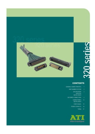
ATI Connectors - 2mm HiRel 3 row style

The document provides information about the 320 series mixed technology connectors, including: - General specifications for materials, electrical ratings, mechanical properties, and environmental specifications. - An overview of the product range including available contact and termination styles. - Detailed dimensional drawings and ordering information for male vertical, male horizontal, female vertical, and female crimp configurations. Special contact and jackscrew options are also described. - Specifications for signal, power, and coax contact types that can be included in the connectors. Crimp termination and tooling details are provided. In under 3 sentences, the summary captures the high level purpose of providing specifications and configuration details for 320 series mixed technology connectors. It

Recommended
Recommended
More Related Content
What's hot
What's hot (12)
Similar to ATI Connectors - 2mm HiRel 3 row style
Similar to ATI Connectors - 2mm HiRel 3 row style (20)
More from Phil Heft
More from Phil Heft (20)
Recently uploaded
Recently uploaded (20)
ATI Connectors - 2mm HiRel 3 row style
- 1. 320series CONTENTS GENERAL CHARACTERISTICS 1 PART NUMBER SYSTEM 2 SPECIFICATION 3 Jackscrews Special contacts 320 SERIES CONNECTORS 4 CHARACTERICS 13 Special contacts COAX Contacts 14 POWER CONTACTS 16 Tooling 61
- 2. www.ati-electronique.fr General characteristics Materials Mouldings: Glass-filled thermoplastic UL94V-0 Female Contacts: Brass shell, with beryllium copper inner contact Male Contacts: Phosphor bronze Finish: See individual pages Electrical Current (individual contacts in isolation): At 25°C 3.3A max At 85°C 2.6A max All contacts simultaneously: At 25°C 3.0A max At 85°C 2.2A max Working Voltage (at sea level 1013 mbar) 240V d.c. or a.c. peak Proof voltage (at sea level 1013 mbar) 360V d.c. or a.c. peak Contact resistance (initial) 20 milliohms max. Contact resistance (after conditioning) 25 milliohms max. Insulation resistance (intial): 1000 Megohms min at 500V d.c. Insulation resistance (after conditioning): 100 Megohms min at 500V d.c. Mechanical Durability: 500 operations Engaging and separating force (per contact pair): 1.0N max, 0.2N min Contact retention in moulding: 10N min. Contact holding force: 0.2N min. Crimp barrel accommodation: 22 A.W.G. to 28 A.W.G. Environmental Environmental classification: 55/125/56 days at 95% RH Operational temperature: – 55ºC to 125ºC Vibration sensitivity: 10Hz to 2000Hz, 0.75mm, 98mm/s2 (10G). duration 6h Bump severity: 390m/s2 (40G), 4000± 10 bumps Shock severity: 981m/s2 (100G) for 6ms Acceleration severity: 490m/s2 (50G) 1 320series
- 3. 2 www.ati-electronique.frAll dimensions in mm. 320 seriesMixed Technology Series PRODUCT RANGE NO. OF SIGNAL CONTACTS NUMBER OF SPECIAL CONTACTS FROM SIGNAL CONTACT NO. 1 SIDE PART NUMBERING SYSTEM TERMINATION STYLE FINISH Y5 Vertical PC Tail, 3mm tail Gold Y6 Vertical PC Tail, 4.5mm tail Gold V5 Horizontal PC Tail, 4mm tail Male only Gold C1 Crimp 24-28 AWG (Small Bore) Female only Gold D1 Crimp 22 AWG (Large Bore) Female only Gold GENDER F Female (Socket) M Male (Plug) NUMBER OF SPECIAL CONTACTS ON OPPOSITE SIDE JACKSCREW VARIANT (see following page) 0 None assembled A Hexagonal slotted jackscrew Female only H Hex socket jackscrew Female only C Panel Guide Female only Y Jackscrew nut only Male only P Jackscrew nut with vertical 3.5mm board mount stud Male only Q Jackscrew nut with vertical 5mm board mount stud Male only S Jackscrew nut with horizontal 5mm board mount bolt Male only 320 – X XXX XX X XXXX XX PART NUMBER OF SPECIAL CONTACT See following page, or 00 if none loaded 320series
- 4. www.ati-electronique.fr 333 All dimensions in mm. MALE FEMALE 30, 31 COAX 40, 41 15, 16, 17 70, 71 75, 76 POWER 80, 81 65, 66, 67 320 seriesSPECIFICATION NONE ASSEMBLED (MALE & FEMALE) 0 FOR MALE ASSEMBLIES Y Jackscrew Nut Only Pages 4 to 7 P or Q Jackscrew Nut with Vertical Board Mount Stud Page 4 S Jackscrew Nut with Horizontal Board Mount Stud Page 5 to 7 FOR FEMALE ASSEMBLIES A Hexagonal Slotted Jackscrew Pages 8 to 12 H Hex Socket Jackscrew Pages 8 to 12 C Guide Pin Pages 8 to 12 JACKSCREWS SPECIAL CONTACTS Pages 4 to 7 *See following pages for dimensional information. *See pages listed above for dimensional information. Page 14 Pages 8 to 12 Page 14 Page 16 Page 16 Page 17 Page 17 Page 15 3 320series
- 5. www.ati-electronique.fr 4 All dimensions in mm. HOW TO ORDER MALE VERTICAL 320 series Male Vertical Choice of compatible jackscrews and special contacts. All contacts are gold finish for full RoHS compliance. Contact ati-marketing@ati-electronique.fr for alternative contact configurations. Diagrams shown with special contact 70 and Jackscrew P assembled. SERIES CODE SPECIAL CONTACTS 30, 31, 70, 71 TAIL Y5 3mm Tail Y6 4.5mm Tail 320 M 008 YX X 0400 XX JACKSCREW 0 No Jackscrew Y Jackscrew Nut P 3.5mm Board Mount Q 5mm Board Mount Recommended PC Board Pattern 14.00 23.00 2.00 1.00 7.70 6.10 TailBoard Mount 3.00 M2 M2 2.00 4.00 29.00 ø4.00 ø0.49 ø1.50 Power Contact No. 1 Contact ø0.65 MIN 2.00 14.00 23.00 2.00 1.00 4.00 12.00 ø1.60 MIN ø2.20 MIN NO. OF L.F. CONTACTS 320series320series
- 6. 55 www.harwin.com All dimensions in mm. www.ati-electronique.fr HOW TO ORDER SERIES CODE NO. OF L.F. CONTACTS 018, 027, 036, 048, 060, 096 320 M XXX V5 X JACKSCREW 0 No Jackscrew Y Jackscrew Nut S 5mm Board Mount 320 series Male Horizontal Choice of compatible jackscrews. All contacts are gold finish for full RoHS compliance. See pages 6 and 7 for configurations including special contacts. Contact ati-marketing@ati-electronique.fr for alternative contact configurations. MALE HORIZONTAL CALCULATION A B + 15 B (No. of L.F. contacts – 3) x 2/3 C B + 9 Diagrams shown with Jackscrew S assembled. Recommended PC Board Pattern B C A 2.00 0.65 7.70 7.00 2.00 M2 M2 ø0.50 2.00 No. 1 Contact C 2.00 2.00 B ø0.65 MIN ø2.20 MIN TAIL V5 4mm Tail 5 320series 320series
- 7. www.ati-electronique.fr 6 All dimensions in mm. HOW TO ORDER SERIES CODE SPECIAL CONTACTS 40, 41, 80, 81 320 M XXX V5 X 0101 XX JACKSCREW 0 No Jackscrew Y Jackscrew Nut S 5mm Board Mount 320 series Male Horizontal Choice of compatible jackscrews and special contacts. All contacts are gold finish for full RoHS compliance. See page 5 for a signal-only configuration, and page 7 for an alternative mixed technology configuration. Contact ati-marketing@ati-electronique.fr for alternative contact configurations. MALE HORIZONTAL CALCULATION A B + 15 B (No. of L.F. contacts + 5) x 2/3 C B + 9 Diagrams shown with special contact 80 and Jackscrew S assembled. B C 2.00 1.00 7.70 0.65 2.00 ø1.50 Power Contact M2 M27.00 ø0.50 2.00 A 3.00 No. 1 Contact B C 2.00 2.00 2.00 2.40 3.00 ø2.20 MIN ø0.65 MIN ø1.60 MIN Recommended PC Board Pattern NO. OF L.F. CONTACTS 019, 025 TAIL V5 4mm Tail 320series320series
- 8. 77 www.harwin.com All dimensions in mm. www.ati-electronique.fr HOW TO ORDER SERIES CODE SPECIAL CONTACTS 40, 41, 80, 81 320 M 013 V5 X 0302 XX JACKSCREW 0 No Jackscrew Y Jackscrew Nut S 5mm Board Mount 320 series Male Horizontal Choice of compatible jackscrews and special contacts. All contacts are gold finish for full RoHS compliance. See page 5 for a signal-only configuration, and page 6 for an alternative mixed technology configuration. Contact ati-marketing@ati-electronique.fr for alternative contact configurations. MALE HORIZONTAL Diagrams shown with special contact 80 and Jackscrew S assembled. Recommended PC Board Pattern 20.00 29.00 2.00 1.00 7.70 0.65 2.00 ø1.50 Power Contact M2 M2 ø0.50 3.00 2.00 35.00 7.00 No. 1 Contact 2.00 20.00 29.00 2.00 2.40 4.00 18.00 ø2.20 MIN ø0.65 MIN ø1.60 MIN 3.00 2.00 NO. OF L.F. CONTACTS TAIL V5 4mm Tail 7 320series 320series
- 9. www.ati-electronique.fr 8 All dimensions in mm. SERIES CODE TAIL Y5 3mm Tail Y6 4.5mm Tail 320 F XXX YX X NO. OF L.F. CONTACTS 027, 036, 048 JACKSCREW 0 No Jackscrew A Hex Slotted Jackscrew H Hex Socket Jackscrew C Guide Pin HOW TO ORDER 320 series Female Vertical Choice of compatible jackscrews. All contacts are gold finish for full RoHS compliance. See pages 9 and 10 for configurations including special contacts. Contact ati-marketing@ati-electronique.fr for alternative contact configurations. FEMALE VERTICAL Diagrams shown with Jackscrew H assembled. B C 8.00 2.00 M2 4.50 3.85 Tail ø0.50 2.00 A No. 1 Contact B 2.00 MIN JACKSCREW ø3.70 2.00 MIN ø0.65 C Recommended PC Board Pattern CALCULATION A B + 15 B (No. of L.F. contacts – 3) x 2/3 C B + 9 320series320series
- 10. 99 www.harwin.com All dimensions in mm. www.ati-electronique.fr HOW TO ORDER 320 series Female Vertical Choice of compatible jackscrews and special contacts. All contacts are gold finish for full RoHS compliance. See page 8 for a signal-only configuration, and page 10 for an alternative mixed technology configuration. Contact ati-marketing@ati-electronique.fr for alternative contact configurations. FEMALE VERTICAL SERIES CODE TAIL Y5 3mm Tail Y6 4.5mm Tail 320 F XXX YX X 0101 XX NO. OF L.F. CONTACTS 019, 025 JACKSCREW 0 No Jackscrew A Hex Slotted Jackscrew H Hex Socket Jackscrew C Guide Pin SPECIAL CONTACTS 35, 36, 75, 76 Diagrams shown with Jackscrew H assembled. B C 1.00 2.00 2.00 M2 2.00 A/F ø3.50 3.00 2.00 A ø0.50 POWER CONTACT ø1.50 Tail 3.85 8.00 4.50 No 1 Contact B C 2.00 3.00 2.00 1.00 2.00 ø3.70 MIN ø0.65 MIN ø1.60 MIN Recommended PC Board Pattern CALCULATION A B + 15 B (No. of L.F. contacts + 5) x 2/3 C B + 9 9 320series 320series
- 11. www.ati-electronique.fr 10 All dimensions in mm. HOW TO ORDER 320 series Female Vertical Choice of compatible jackscrews and special contacts. All contacts are gold finish for full RoHS compliance. See page 8 for a signal-only configuration, and page 9 for an alternative mixed technology configuration. Contact ati-marketing@ati-electronique.fr for alternative contact configurations. FEMALE VERTICAL SERIES CODE TAIL Y5 3mm Tail Y6 4.5mm Tail 320 F 013 YX X 0302 XX NO. OF L.F. CONTACTS JACKSCREW 0 No Jackscrew A Hex Slotted Jackscrew H Hex Socket Jackscrew C Guide Pin SPECIAL CONTACTS 35, 36, 75, 76 Diagrams shown with special contact 75 and Jackscrew C assembled. Recommended PC Board Pattern 20.00 29.00 1.00 2.00 2.00 ø1.50 3.70 2.00 3.00 4.00 35.00 8.00 3.85 4.50 Tail ø0.50 ø1.50 Power Contact No 1 Contact ø0.65 2.00 20.00 2.00 1.00 4.00 3.00 18.00 2.00ø1.60 320series320series
- 12. 1111 www.harwin.com All dimensions in mm. www.ati-electronique.fr FEMALE CRIMP CRIMP CONTACTS 320 series Female Crimp SERIES CODE CRIMPS C1 Small Bore D1 Large Bore 320 F XXX X1 X JACKSCREW 0 No Jackscrew A Hex Slotted Jackscrew H Hex Socket Jackscrew C Guide Pin HOW TO ORDER NO. OF L.F. CONTACTS 018, 054, 060, 096 Diagrams shown with Jackscrew H assembled. TOOLS ø1.1 Max. 2.0 Nominal Recommended Crimp Tool – M22520/2-01 Positioner – MP6818 Contact Insertion/Removal Tool – 220S03 See pages 18 to 19 WIRE STRIPPING DETAILS Choice of compatible jackscrews. All contacts are gold finish for full RoHS compliance. See page 12 for configurations including special contacts. Contact ati-marketing@ati-electronique.fr for alternative contact configurations. B C A 2.00 2.00 M2 6.70 3.85 8.00 No. 1 Contact 7.45 CALCULATION A B + 15 B (No. of L.F. contacts – 3) x 2/3 C B + 9 Large Bore (22 AWG): Small Bore (24-28 AWG): SMALL BORE IDENT GROOVE 11 320series 320series
- 13. www.ati-electronique.fr 12 All dimensions in mm. SERIES CODE CRIMPS C1 Small Bore D1 Large Bore 320 F XXX X1 X XXXX XX 008 0400 019 0101 SIGNAL/SPECIAL CONFIGURATIONS JACKSCREW 0 No Jackscrew A Hex Slotted Jackscrew H Hex Socket Jackscrew C Guide Pin HOW TO ORDER SPECIAL CONTACTS 15, 16, 17, 65, 66, 67 320 series Female Crimp 08 – 0400 CONFIGURATION 19 – 0101 CONFIGURATION CRIMP CONTACTS TOOLS WIRE STRIPPING DETAILS ø1.1 Max. 2.0 Nominal Recommended Crimp Tool – M22520/2-01 Positioner – MP6818 Contact Insertion/Removal Tool – 220S03 See pages 18 to 19 Choice of compatible jackscrews and special contacts. All contacts are gold finish for full RoHS compliance. See page 11 for signal-only configurations. Contact ati-marketing@ati-electronique.fr for alternative contact configurations. 7.45 2.00 14.00 23.00 2.00 1.00 4.00 M2 2.00 A/F ø3.50 29.00 8.00 3.85 6.70 No. 1 Contact 2.00 16.00 25.00 2.00 1.00 2.00 M2 14.00 2.00 A/F ø3.50 31.00 8.00 3.85 6.70 No. 1 Contact Large Bore (22 AWG): Small Bore (24-28 AWG): SMALL BORE IDENT GROOVE 320series320series
- 14. www.ati-electronique.fr 131313 All dimensions in mm. Special Contacts Materials Retaining clip: Beryllium copper, nickel plated Other metallic parts: Copper alloy, Gold plated Insulator: PTFE Electrical Operating voltage (sea level): 180V a.c. Rms under 500 mA Maximum voltage (sea level): 1000V a.c. Rms Contact resistance: 6 m max Insulation resistance: 106 M at 250V a.c. Rms Electrical (coaxial contacts) Frequency range: 6 GHz (depending on cable) Impedance: 50 Ohms V.S.W.R.: < 1.35 Mechanical Endurance: 500 cycles Insertion force: 5N max, 0.6N min Withdrawal force: 2N max, 0.5N min Contact replacement in connector: 5 times Environmental Operating temperature: -55°C to +125°C Salt spray test: 96 hrs Humidity test: 56 days CHARACTERISTICS 13 320series
- 15. www.ati-electronique.fr 14 All dimensions in mm. Coax Contacts Male PC Tail 6 GHz coaxial performance. For specification see page 13. 50 Ohms impedance. VERTICAL HORIZONTAL square3.00 Tail 0.30 5.10 2.00 2.00 TAIL LENGTH ORDER CODE (LOOSE) PART CODE (FITTED) 3.0mm 220M30* 30 4.5mm 220M31* 31 2.00 1.00 3.00 Tail .003 6.10 5.10 2.50 TAIL LENGTH ORDER CODE (LOOSE) PART CODE (FITTED) 3.0mm 220M40* 40 4.5mm 220M41* 41 * Not available for sale * Not available for sale 320series
- 16. 1515 www.harwin.com All dimensions in mm. www.ati-electronique.fr Coax Contacts Female Crimp 6 GHz co-axial performance. 50 Ohms impedance. Contacts are removable using extraction tool 220 S07 (see page 19). CRIMP STRAIGHT 4.001.00 1.70 WIRE STRIPPING DETAILS 6.70 1.30 5.40 3.00 square CABLE DIAMETER ORDER CODE (LOOSE) PART CODE (WITH ASSEMBLY) 2.0mm 220F15 15 2.4mm 220F16 16 2.7mm 220F17 17 15 320series
- 17. www.ati-electronique.fr 16 All dimensions in mm. Power Contacts Male PC Tail 20A max current rating. square3.00 Ø1.50 Tail 0.30 5.10 TAIL LENGTH ORDER CODE (LOOSE) PART CODE (FITTED) 3.5 mm 220M70* 70 5.0 mm 220M71* 71 5.10 6.10 3.00 Ø1.50 Tail 2.50 3.00 TAIL LENGTH ORDER CODE (LOOSE) PART CODE (FITTED) 3.5 mm 220M80* 80 5.0 mm 220M81* 81 VERTICAL HORIZONTAL Position : see page 4 Position : see page 4 * Not available for sale * Not available for sale 320series
- 18. 1717 www.harwin.com All dimensions in mm. www.ati-electronique.fr Power Contacts Female 20A max current rating. Crimp Contacts are removable using extraction tool 220 S07 (see page 19). VERTICAL PC TAIL CABLE DIAMETER (MAX) AWG CURRENT RATING ORDER CODE (LOOSE) PART CODE (WITH ASSEMBLY) 2.3mm 12 20A 220F65 65 2.0mm 14 15A 220F66 66 1.5mm 16 10A 220F67 67 6.00 0.50 6.70 3.00 square 3.00 square 0.30 4.60 Ø1.50 Tail TAIL LENGTH ORDER CODE (LOOSE) PART CODE (FITTED) 3.5mm 220F75* 75 5.0mm 220F76* 76 SOLDER STRAIGHT * Not available for sale 17 320series
- 19. 18 www.ati-electronique.fr 18 All dimensions in mm. 320 series Tooling POSITIONER POSITIONER ORDER CODE Female crimp MP6818 Used with hand crimp tool shown opposite. Standard circular crimp tool BS5210-3A-300 and MIL specification M22520/2-01. Precision tool with ratchet mechanism and 8-indent form. Must be used with positioner opposite. Instruction sheet available. Used with hand crimp tool shown opposite. Standard circular crimp tool. Precision tool with ratchet mechanism and 8-indent form. Must be used with positioner opposite. Instruction sheet available. ORDER CODE Signal contacts M22520/2-01 ORDER CODE Inner contact of coax contacts 220S04 HAND CRIMP TOOL HAND CRIMP TOOL Standard circular crimp tool BS5210-3A-300 and MIL specification M22520/2-01. Precision tool with ratchet mechanism and 8-indent form. Must be used with positioner opposite. Instruction sheet available. ORDER CODE Inner contact of coax contacts MH800 Standard circular crimp tool. Precision tool with ratchet mechanism and 8-indent form. Must be used with positioner opposite. Instruction sheet available. 320series
- 20. 1919 www.harwin.com All dimensions in mm. www.ati-electronique.fr 19 320 series Tooling REMOVAL TOOL ORDER CODE Outer sleeve of coax contacts 220S05 Crimp tool HX3 Standard coax crimp tool for crimping the outer sleeve of coax contacts. Instruction sheet available. For inserting crimped contacts into the rear of mouldings. Instruction sheet available. Suitable for all signal contacts. To aid removal of special cable contacts from connectors. ORDER CODE Signal crimps 220S03 HAND CRIMP TOOL INSERTION/REMOVAL TOOL ORDER CODE Special cable connectors 220S07 19 320series
- 21. 20 www.ati-electronique.fr 20 All dimensions in mm. This catalogue only refers to the standard types. ATI also realizes any special connector and any coaxial cable installation on request. Please, take advice. Adress all correspondence to : ATI - 91031 EVRY Cedex - France ati-marketing@ati-electronique.fr 320series
- 22. 6 rue Jean Mermoz - ZA de St-Guénault 91080 COURCOURONNES - FRANCE Tél. : 33 (0)1 69 36 94 00 - Fax 33 (0)1 64 97 14 84 Courriel : ati-marketing@ati-electronique.fr www.ati-electronique.fr