
Recommended
Recommended
More Related Content
More from olfjsekdmmes
More from olfjsekdmmes (20)
Recently uploaded
Recently uploaded (20)
Nissan forklift internal combustion f03 series service repair manual
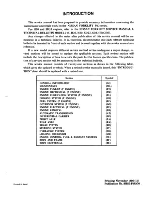
- 1. INTRODUCTION This service manual has been prepared to provide necessary information concerning the maintenance and repair work on the NISSAN FORKLIFT F03 series. For H30 and SD33 engines, refer to the NISSAN FORKLIFT SERVICE MANUAL & TECHNICAL BULLETIN MODEL J15, H20, H30, 5022, 5033 ENGINE. Any changes effected in the series after publication of this service manual will be an- nounced in a technical bulletin. It is, therefore, recommended that each relevant technical bulletin be inserted in front of each section and be used together with the service manual as a reference. If a new model requires different service method or has undergone a major change, re- vised sections will be issued to replace the applicable sections. Each revised section will include the description of how to service the parts for the former specifications. The publica- tion of a revised section will be announced in the technical bulletin. This service manual consists of twenty-one sections as shown in the following table, which gives the updated symbols. When a revised service manual is issued, this "INTRODUC- TION" sheet should be replaced with a revised one. Section Symbol GENERAL INFORMATION (GI) MAINTENANCE (MA) ENGINE TUNE-UP (P ENGINE) (ET) ENGINE MECHANICAL (P ENGINE) (EM) ENGINE LUBRICATION SYSTEM (P ENGINE) (EL) COOLING SYSTEM (P ENGINE) (CO) FUEL SYSTEM (P ENGINE) (EF) GOVERNOR SYSTEM (P ENGINE) (GO) ENGINE ELECTRICAL (P ENGINE) (EE) ENGINE REMOVAL (ER) AUTOMATIC TRANSMISSION (AT) DIFFERENTIAL CARRIER (DF) FRONT AXLE (FA) REAR AXLE (RA) BRAKE SYSTEM (BR) STEERING SYSTEM (ST) HYDRAULIC SYSTEM (HD) LOADING MECHANISM (LM) ENGINE CONTROL, FUEL & EXHAUST SYSTEMS (FE) BODY AND FRAME (BF) BODY ELECTRICAL (BE) Printed in Japan Printing: November 1996 (11) Publication No. SMOE.FOS2GO
- 2. ENGINE LUBRICATION SYSTEM ENGINE LUBRICATION SYSTEM -p Engine- (EL) CONTENTS SERVICE DATA AND SPECIFICATIONS EL-2 TROUBLE DIAGNOSES AND CORRECTIONS EL-3 ENGINE LUBRICATION SySTEM EL-4 LUBRICATION CiRCUiT EL-4 01 L PUMP EL-5 OIL FILT ER . . . . . . . . . . . . . . . . . . . . . . . . . . . . . . . . . . . . . . . . . . . . . . . . . . .. EL-6 SPECIAL SERVICE TOOL EL-6
- 3. Service Data and Specifications - ENGINE LUBRICATION SYSTEM SERVICE DATA AND SPECIFICATIONS GENERAL SPECIFICATIONS Lubrication method Pressedfeed flow Oil pump type Spur gear type Oil filter type Full flow and cartridge type Oil capacity Q (US qt, Imp qt) With oil filter 5.0 (5-1/4,4-3/8) Without oil filter 4.3 (4-1/2,3-314) TIGHTENING TORQUE Unit N.m kg-m ft-Ib Oil pump mounting o , bolts 25 - 34 '.'0. 2.5 - 3.5 18 - 25 Oil pump cover bolt 7-9 0.7 - 0.9 5.1 - 6.5 Oil pan drain plug 20 - 39 2.0-4.0 14 - 29 Oil pan bolt 8 -14 0.8 - 1.4 5.8 -10.1 INSPECTION AND ADJUSTMENT Oil pump Unit: mm (in) Pump gear to pump body clearance Pump gear backlash Pump gear vertical clearance Lessthan 0.26 (0.0102) Lessthan 0.51 (0,0201) Lessthan 0.115 (0.0045) EL-2 SLC136
- 4. ENGINE LUBRICATION SYSTEM - Trouble Diagnoses and Corrections TROUBLE DIAGNOSES AND CORRECTIONS Condition Probable cause Corrective action Oil leakage Damaged or cracked pump body cover. Replace. Oil leakage from gasket and oil seal. Replace. Oil leakage from regulator valve. Tighten or replace. Oil leakage from blind plug. Replace. Decreased oil Lack of oil in engine oil pan. Correct. pressure Dirty oil strainer. Clean or replace. Damaged or worn pump rotors/gears. Replace. Malfunctioning regulator. Replace. Use of poor quality engine oil. Replace. Warning light Decreased oil pressure. Previously mentioned. remains "on" - Oil pressure switch unserviceable. Replace. engine running Electrical fault. Check circuit. Noise Excessive backlash in pump rotors. Replace. EL-3
- 5. EngineLubricationSystem- ENGINE LUBRICATION SYSTEM ENGINE LUBRICATION SYSTEM LUBRICATION CIRCUIT El.4 ./l---, Oil gallery in ......- cylinder block ...... - - Oil splash .....- Oil passage SLC132
- 6. ENGINE LUBRICATION SYSTEM - Engine Lubrication System 5.0 (5.1/4, 4.3/8) 4.3 (4-1/2, 3.3/4) Unit: Q (US qt, Imp qt) Without oil filter With oil filter 6. Insert distributor, meshing dis. tributor drive slit and driven slit. 7. Refill engine with oil. (2) Insert and turn oil pump spindle clockwise. (3) Confirm that slit on oil pump spindle deflects as shown. Oil capacity ////0 C;I~d:r ~I~C~/ ///// I SLC146 SLC145 //UJ/JIi~d;:~I~CYL/J// 1-200 5. Install oil pump spindle as follows: (1) Set oil pump spindle as shown. ~ - 2::://~ ~- / SLC133 OIL PUMP REMOVAL 1. Remove oil pan drain plug, and allow oil to drain. 2. Remove distributor and oil pump spindle. 3. Remove oil pan. 4. Remove oil pump body. DISASSEMBLY AND ASSEMBLY INSTALLATION 1. Before installing oil pump in engine, turn crankshaft so that No.1 piston is at T.D.C. 2. Install oil pump on cylinder block. [f:l : Oil pump mounting bolts 25 -34 N'm (2.5 • 3.5 kg-m, 18 - 25 ft-Ib) 3. Install oil pan. [f:l : Oil pan bolt 8-14 N.m (0.8 - 1.4 kg-m, 5.8 - 10.1 ft-Ibl 4. Rotate oil pump shaft with a con- ventional screwdriver as shown. Oil pump drive shaft set v~ t-t!l 25 - 34 (2.5 - 3.5, 18-25) ~. Regulator.., ~'. Oil pump valve / . strainer (!) Pin~Washer assembly , Spring ~. Regulator valve set t!l: N.m (kg-m, ft-Ib) SLC135 EL.5
- 7. Special Service Tool- ENGINE LUBRICATION SYSTEM INSPECTION 1. Inspect the following for wear or damage. • Pump body and cover • Pump gears • Drive spindle Pump gears and body are not serviced separately. If pump gears or body are damaged or worn, replace drive shaft set or entire oil pump assembly. 2. Using a feeler gauge, check the following clearance. If it exceeds the limit, replace drive shaft set or entire oil pump assembly. Pump gear to pump body: less than 0.26 mm (0.0102 in) Pump gear backlash less than 0.51 mm (0.0201 in) Pump gear vertical clearance less than 0.115 mm (0.0045 in) 3. Check oil pressure regulator valve sliding surface and valve spring. If damaged, replace valve set or pump assembly. rPin I ~ .--..c::;egUlator v~ve i~spnng iJ ~r"'" SLC137 OIL FILTER REPLACEMENT 1. Remove oil pan drain plug, and allow oil to drain. 2. Using Tool, remove oil filter. 3. Wipe oil filter mounting surface with clean rag. 4. Check oil pressure relief valve for cracks or breaks. If necessary. remove valve by pry- ing it out with a screwdriver. Install a new valve by tapping it in place. 5. Smear a little engine oil on rubber gasket of oil filter. 6. Install oil filter. Hand-tighten ONLY. DO NOT use a wrench to tighten the filter. 7. Refill engine with oil. Oil capacity: 5.0 liters (5-1/4 US qt, 4-3/8 Imp qt) 8. Run engine for a few minutes, and check for leaks. Tool number SPECIAL SERVICE TOOL Tool name ST19320000 EL-6 Oil filter wrench
- 17. Thank you very much for your reading. Please Click Here. Then Get COMPLETE MANUAL. NO WAITING NOTE: If there is no response to click on the link above, please download the PDF document first and then click on it.