SlideShare a Scribd company logo
1 of 12
SCR (silicon- controlled rectifier) :- An SCR is a three-terminal, three-
junction, and four-layer semiconductor device that is used to perform
switching functions in power circuits. Sometimes the SCR is also called
as Thyristor.
SCR (semiconductor controlled rectifier):- एक तीन-टर्मिनल, तीन-जंक्शन और
चार-परत अर्िचालक उपकरण है र्जसका उपयोग power circuit में switching
functions करने क
े र्लए र्कया जाता है। कभी-कभी SCR को Thyristor भी कहा
जाता है।
Construction:- SCR has four layers of extrinsic semiconductor materials.
These four-layer forms three PN junctions named J1, J2, and J3. The
layers are either NPNP or PNPN. The anode and cathode terminals are
placed at the end layers and where the gate terminal is placed with the
third layer. The outer layers are heavily doped and the inner two layers
are lightly doped.
SCR में extrinsic semiconductor materials की चार layer होती हैं। ये four –
layer तीन PN जंक्शन बनाती हैं र्जनका नाम J1, J2 और J3 है। परतें या तो NPNP
या PNPN हैं। anode और cathode टर्मिनलों को अंर्तम परतों पर रखा जाता है और
जहां gate terminal को तीसरी परत क
े साथ रखा जाता है। बाहरी परतों को भारी
मात्रा में doped र्कया जाता है और भीतरी दो परतों को हल्क
े से doped र्कया जाता
है।
In the schematic diagram, the three terminal of SCR is shown to be
Anode, cathode and Gate. The terminal connected to the outer
region p is called Anode, the terminal connected to outer region n
is called Cathode and that connected to inner p region is called
Gate.
 SCR Working:- SCR working depends upon the battery polarity and the
gate input. The SCR can operate in three different modes.
1 Forward Blocking Mode
2 Forward Conduction Mode
3 Reverse Blocking Mode
 1 Forward Blocking Mode:- When anode of SCR connects to the
positive and cathode of SCR with the negative of the battery terminal.
And no pulse is applied at the gate terminal. The SCR work in the
forward blocking mode. This means that SCR will not conduct even
though the polarity of SCR is forward bias. In forward blocking mode, the
J1 and J3 PN junctions are forward biased. But the middle junction J2 is
reverse biased, therefore, the SCR will not conduct in the forward
blocking mode.
जब SCR का anode battery क
े positive terminal और cathode negative
terminal से जुड़ता है। और gate terminal पर कोई pulse नहीं लगाया जाता है।
SCR forward blocking mode में काम करता है। इसका मतलब यह है र्क SCR
का संचालन नहीं होगा, भले ही SCR की polarity forward bias है। Forward
Blocking Mode में, J1 और J3 PN जंक्शन forward biased होते हैं। लेर्कन मध्य
जंक्शन J2 reverse biased है, इसर्लए, SCR forward blocking mode में संचालन
नहीं करेगा।
 Forward Blocking Mode:-
Kaushik classes
Vgs=0V
• Forward Conduction Mode:- Forward conduction mode is the only
mode of SCR for conduction. The SCR can be set into the forward
conduction mode in two ways.
• First by providing the gate pulse to forward bias the J2 junction.
• Second by increasing the anode to cathode voltage to break down the
J2 junction.
• The gate pulse method is preferred and suitable for many
applications. The breakdown method reduces the SCR lifetime.
• The SCR will remain in conduction mode even after removal of the
gate pulse or reducing the applied voltage. If the anode current of the
SCR drops below the holding current the SCR will stop falling back to
forward blocking mode.
• Forward conduction mode, conduction क
े र्लए SCR का एकमात्र तरीका
है। SCR को दो तरह से Forward conduction mode में सेट र्कया जा सकता है।
सबसे पहले J2 junction को forward bias करने क
े र्लए gate pulse परदान
करते हैं।
• दू सरा, J2 junction को breakdown क
े र्लए anode को cathode voltage में
बढाकर। गेट पल्स र्िर्र् पसंदीदा है और कई अनुप्रयोगों क
े र्लए उपयुक्त है।
breakdown method SCR क
े जीिनकाल को कम कर देती है। गेट पल्स को
हटाने या लागू िोल्टेज को कम करने क
े बाद भी SCR conduction mode में
रहेगा। यर्द SCR का anode current holding current से नीचे चला जाता है तो
SCR िापस forward blocking mode में र्गरना बंद कर देगा।
 Forward Conduction Mode:-
Kaushik classes
 Reverse Blocking Mode in SCR:-
 If the anode terminal of the SCR connects to the negative and cathode
terminal of SCR connects to the positive of battery terminals. The SCR is
in reverse blocking mode. In this mode, J1 and J3 junctions are reverse
biased. Where the middle junction J2 is forward bias. As two junctions are
reverse bias, so there is no current flowing through it but only a small
leakage current due to the drift charge carrier.
 SCR में Reverse blocking mode यर्द SCR का anode terminal negative से
जुड़ता है और SCR का cathode terminal battery terminals क
े positive से जुड़ता
है। SCR reverse blocking mode में है। इस mode में, J1 और J3 junction
reverse bias हैं। जहां middle junction J2 forward bias है। चूंर्क दो (J1 and J3)
junction reverse bias हैं, इसर्लए इसमें कोई current प्रिार्हत नहीं होता है, लेर्कन
drift charge carrier क
े कारण क
े िल एक small leakage current होता है।
 Reverse Blocking Mode in SCR:-
Vgs=0V
 VI Characteristics of SCR:-
 The curve of VI characteristics of SCR is obtained by changing the voltage across
the SCR and noticing the current through SCR. When connecting in reverse
polarity, the SCR will conduct a small current, leakage current up to breakdown
voltage, VBR. After that point, the SCR will break down and start to act like a short
circuit. Below the breakdown point, the region is called reverse blocking mode.
 SCR क
े VI characteristic का curve SCR में िोल्टेज को बदलकर और SCR क
े माध्यम से करंट
को नोर्टस करक
े प्राप्त र्कया जाता है। reverse polarity में कनेक्ट करते समय, SCR ब्रेकडाउन
िोल्टेज, VBR तक एक small current , leakage current conduct करेगा। उस point क
े बाद,
SCR break down जाएगा और short circuit की तरह काम करना शुरू कर देगा। breakdown
point क
े नीचे क
े region को reverse blocking modeकहा जाता है।
 If connect in the forward polarity, the SCR will not allow any current.
This region is called forward blocking mode, the region is below the
VBO point
 यर्द forward polarity में जुड़ते हैं, तो SCR र्कसी भी करंट की अनुमर्त नहीं देगा।
इस region को forward blocking mode कहा जाता है, यह क्षेत्र VBO point से नीचे
है।
 When the voltage reaches the VBO point, the SCR starts the current flow.
Alternatively, the SCR can be put into the forward conduction mode by
applying the gate that will increase the anode current above the latching
current. A higher gate current can put SCR faster in the forward
conduction mode as in the graph Ig3>Ig2>Ig1. The SCR will remain in
the forward conduction mode if the anode current is above the holding
current.
 जब voltage VBO र्बंदु तक पहंचता है, तो SCR current flow शुरू कर देता है।
िैकल्पिक रूप से, SCR को gate लगाने से forward conduction mode में रखा जा
सकता है जो latching current क
े ऊपर anode current को बढाएगा। एक higher
gate current SCR को तेजी से forward conduction mode में डाल सकता है जैसा
र्क ग्राफ Ig3>Ig2>Ig1 में है। अगर anode current holding current से ऊपर है तो
SCR forward conduction mode में रहेगा।
 SCR Applications:-
 The most common SCR application is the DC motor speed
control
 The silicon controlled rectifier (SCR) is used in AC voltage
stabilizers.
 The silicon controlled rectifier (SCR) is used as switch.
 It is used in choppers.
 The silicon controlled rectifier (SCR) is used in inverters.
 The silicon controlled rectifier (SCR) is used for power
control.
 It is used for DC circuit breaker.
 Silicon control rectifier (SCR) is used in battery charger.
 It is used to Adjust light dimmer.
 It is used to control motors speed.
 The SCR is used in pulse circuit.
 It is used for AC power control with solid relay.

More Related Content

What's hot (20)

Scr basics
Scr   basicsScr   basics
Scr basics
 
Diac
DiacDiac
Diac
 
Silicon controlled rectifier
Silicon controlled rectifierSilicon controlled rectifier
Silicon controlled rectifier
 
Thyristor
Thyristor Thyristor
Thyristor
 
SCR.pptx
SCR.pptxSCR.pptx
SCR.pptx
 
Silicon control rectifier
Silicon control rectifierSilicon control rectifier
Silicon control rectifier
 
Thyristor Characteristics, Two Transistor Model Of Thyristor & Thyrisror Turn...
Thyristor Characteristics, Two Transistor Model Of Thyristor & Thyrisror Turn...Thyristor Characteristics, Two Transistor Model Of Thyristor & Thyrisror Turn...
Thyristor Characteristics, Two Transistor Model Of Thyristor & Thyrisror Turn...
 
Scr
ScrScr
Scr
 
PROTECTION CIRCUIT OF SCR
PROTECTION CIRCUIT OF SCRPROTECTION CIRCUIT OF SCR
PROTECTION CIRCUIT OF SCR
 
controlled rectifiers
controlled rectifierscontrolled rectifiers
controlled rectifiers
 
Single phase full bridge inverter
Single phase full bridge inverterSingle phase full bridge inverter
Single phase full bridge inverter
 
TRIAC Working
TRIAC WorkingTRIAC Working
TRIAC Working
 
Power MOSFET
Power MOSFETPower MOSFET
Power MOSFET
 
Ujt uni junction transistor - basics
Ujt   uni junction transistor - basicsUjt   uni junction transistor - basics
Ujt uni junction transistor - basics
 
Thyristor family
Thyristor familyThyristor family
Thyristor family
 
Thyristor
ThyristorThyristor
Thyristor
 
Power Electronics - DIAC & TRIAC
Power Electronics - DIAC & TRIACPower Electronics - DIAC & TRIAC
Power Electronics - DIAC & TRIAC
 
Unit-1 Power Semiconductor devices
Unit-1 Power Semiconductor devicesUnit-1 Power Semiconductor devices
Unit-1 Power Semiconductor devices
 
Silicon controlled rectifier (scr)
Silicon controlled rectifier (scr)Silicon controlled rectifier (scr)
Silicon controlled rectifier (scr)
 
Power Electronics
Power ElectronicsPower Electronics
Power Electronics
 

construction working and characteristic of SCR

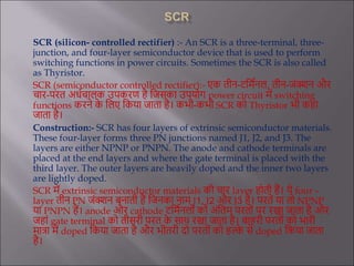
  • 1. SCR (silicon- controlled rectifier) :- An SCR is a three-terminal, three- junction, and four-layer semiconductor device that is used to perform switching functions in power circuits. Sometimes the SCR is also called as Thyristor. SCR (semiconductor controlled rectifier):- एक तीन-टर्मिनल, तीन-जंक्शन और चार-परत अर्िचालक उपकरण है र्जसका उपयोग power circuit में switching functions करने क े र्लए र्कया जाता है। कभी-कभी SCR को Thyristor भी कहा जाता है। Construction:- SCR has four layers of extrinsic semiconductor materials. These four-layer forms three PN junctions named J1, J2, and J3. The layers are either NPNP or PNPN. The anode and cathode terminals are placed at the end layers and where the gate terminal is placed with the third layer. The outer layers are heavily doped and the inner two layers are lightly doped. SCR में extrinsic semiconductor materials की चार layer होती हैं। ये four – layer तीन PN जंक्शन बनाती हैं र्जनका नाम J1, J2 और J3 है। परतें या तो NPNP या PNPN हैं। anode और cathode टर्मिनलों को अंर्तम परतों पर रखा जाता है और जहां gate terminal को तीसरी परत क े साथ रखा जाता है। बाहरी परतों को भारी मात्रा में doped र्कया जाता है और भीतरी दो परतों को हल्क े से doped र्कया जाता है।
  • 2. In the schematic diagram, the three terminal of SCR is shown to be Anode, cathode and Gate. The terminal connected to the outer region p is called Anode, the terminal connected to outer region n is called Cathode and that connected to inner p region is called Gate.
  • 3.  SCR Working:- SCR working depends upon the battery polarity and the gate input. The SCR can operate in three different modes. 1 Forward Blocking Mode 2 Forward Conduction Mode 3 Reverse Blocking Mode  1 Forward Blocking Mode:- When anode of SCR connects to the positive and cathode of SCR with the negative of the battery terminal. And no pulse is applied at the gate terminal. The SCR work in the forward blocking mode. This means that SCR will not conduct even though the polarity of SCR is forward bias. In forward blocking mode, the J1 and J3 PN junctions are forward biased. But the middle junction J2 is reverse biased, therefore, the SCR will not conduct in the forward blocking mode. जब SCR का anode battery क े positive terminal और cathode negative terminal से जुड़ता है। और gate terminal पर कोई pulse नहीं लगाया जाता है। SCR forward blocking mode में काम करता है। इसका मतलब यह है र्क SCR का संचालन नहीं होगा, भले ही SCR की polarity forward bias है। Forward Blocking Mode में, J1 और J3 PN जंक्शन forward biased होते हैं। लेर्कन मध्य जंक्शन J2 reverse biased है, इसर्लए, SCR forward blocking mode में संचालन नहीं करेगा।
  • 4.  Forward Blocking Mode:- Kaushik classes Vgs=0V
  • 5. • Forward Conduction Mode:- Forward conduction mode is the only mode of SCR for conduction. The SCR can be set into the forward conduction mode in two ways. • First by providing the gate pulse to forward bias the J2 junction. • Second by increasing the anode to cathode voltage to break down the J2 junction. • The gate pulse method is preferred and suitable for many applications. The breakdown method reduces the SCR lifetime. • The SCR will remain in conduction mode even after removal of the gate pulse or reducing the applied voltage. If the anode current of the SCR drops below the holding current the SCR will stop falling back to forward blocking mode. • Forward conduction mode, conduction क े र्लए SCR का एकमात्र तरीका है। SCR को दो तरह से Forward conduction mode में सेट र्कया जा सकता है। सबसे पहले J2 junction को forward bias करने क े र्लए gate pulse परदान करते हैं। • दू सरा, J2 junction को breakdown क े र्लए anode को cathode voltage में बढाकर। गेट पल्स र्िर्र् पसंदीदा है और कई अनुप्रयोगों क े र्लए उपयुक्त है। breakdown method SCR क े जीिनकाल को कम कर देती है। गेट पल्स को हटाने या लागू िोल्टेज को कम करने क े बाद भी SCR conduction mode में रहेगा। यर्द SCR का anode current holding current से नीचे चला जाता है तो SCR िापस forward blocking mode में र्गरना बंद कर देगा।
  • 6.  Forward Conduction Mode:- Kaushik classes
  • 7.  Reverse Blocking Mode in SCR:-  If the anode terminal of the SCR connects to the negative and cathode terminal of SCR connects to the positive of battery terminals. The SCR is in reverse blocking mode. In this mode, J1 and J3 junctions are reverse biased. Where the middle junction J2 is forward bias. As two junctions are reverse bias, so there is no current flowing through it but only a small leakage current due to the drift charge carrier.  SCR में Reverse blocking mode यर्द SCR का anode terminal negative से जुड़ता है और SCR का cathode terminal battery terminals क े positive से जुड़ता है। SCR reverse blocking mode में है। इस mode में, J1 और J3 junction reverse bias हैं। जहां middle junction J2 forward bias है। चूंर्क दो (J1 and J3) junction reverse bias हैं, इसर्लए इसमें कोई current प्रिार्हत नहीं होता है, लेर्कन drift charge carrier क े कारण क े िल एक small leakage current होता है।
  • 8.  Reverse Blocking Mode in SCR:- Vgs=0V
  • 9.  VI Characteristics of SCR:-  The curve of VI characteristics of SCR is obtained by changing the voltage across the SCR and noticing the current through SCR. When connecting in reverse polarity, the SCR will conduct a small current, leakage current up to breakdown voltage, VBR. After that point, the SCR will break down and start to act like a short circuit. Below the breakdown point, the region is called reverse blocking mode.  SCR क े VI characteristic का curve SCR में िोल्टेज को बदलकर और SCR क े माध्यम से करंट को नोर्टस करक े प्राप्त र्कया जाता है। reverse polarity में कनेक्ट करते समय, SCR ब्रेकडाउन िोल्टेज, VBR तक एक small current , leakage current conduct करेगा। उस point क े बाद, SCR break down जाएगा और short circuit की तरह काम करना शुरू कर देगा। breakdown point क े नीचे क े region को reverse blocking modeकहा जाता है।  If connect in the forward polarity, the SCR will not allow any current. This region is called forward blocking mode, the region is below the VBO point  यर्द forward polarity में जुड़ते हैं, तो SCR र्कसी भी करंट की अनुमर्त नहीं देगा। इस region को forward blocking mode कहा जाता है, यह क्षेत्र VBO point से नीचे है।
  • 10.
  • 11.  When the voltage reaches the VBO point, the SCR starts the current flow. Alternatively, the SCR can be put into the forward conduction mode by applying the gate that will increase the anode current above the latching current. A higher gate current can put SCR faster in the forward conduction mode as in the graph Ig3>Ig2>Ig1. The SCR will remain in the forward conduction mode if the anode current is above the holding current.  जब voltage VBO र्बंदु तक पहंचता है, तो SCR current flow शुरू कर देता है। िैकल्पिक रूप से, SCR को gate लगाने से forward conduction mode में रखा जा सकता है जो latching current क े ऊपर anode current को बढाएगा। एक higher gate current SCR को तेजी से forward conduction mode में डाल सकता है जैसा र्क ग्राफ Ig3>Ig2>Ig1 में है। अगर anode current holding current से ऊपर है तो SCR forward conduction mode में रहेगा।
  • 12.  SCR Applications:-  The most common SCR application is the DC motor speed control  The silicon controlled rectifier (SCR) is used in AC voltage stabilizers.  The silicon controlled rectifier (SCR) is used as switch.  It is used in choppers.  The silicon controlled rectifier (SCR) is used in inverters.  The silicon controlled rectifier (SCR) is used for power control.  It is used for DC circuit breaker.  Silicon control rectifier (SCR) is used in battery charger.  It is used to Adjust light dimmer.  It is used to control motors speed.  The SCR is used in pulse circuit.  It is used for AC power control with solid relay.