Miter gear box 2 1, angle grinder gearbox ratio, 2 to 1 ratio right angle gearbox oil type, t gear miter box, small 90 degree gear box suppliers, manufacturers

Miter gear box 2:1, angle grinder gearbox ratio, 2 to 1 ratio right angle gearbox oil type, t gear miter box, small 90 degree gear box Input power from 0.1 Kw to 157 Kw. Transmission torque from 9 Nm to 1299 Nm. 1:1 ratio, 1.5:1, 2:1, 3:1, 4:1, 5:1 gear reduction ratios, custom speed increaser 1:1.5, 1:2, 1:3 gear increasing ratio. Input and output speed from 10 rpm to 2000 rpm, custom higher speed 3000 rpm. High efficiency from 95% to 98%. Input and output shaft diameter from 11 mm to 60 mm. 12 types input and output shaft arrangements and rotation directions, shafts can be rotated clockwise and counterclockwise rotation directions. Solid shaft, hollow shaft and flange adapter are suitable, custom multiple spine keys. Horizontal mounting, overhung mounting or wall mounting are suitable. Two way gear box, three way gear box, four way gear box and five way gear box are suitable. Low backlash, quiet running, low temperature, high torque features.

Recommended
Recommended
More Related Content
Similar to Miter gear box 2 1, angle grinder gearbox ratio, 2 to 1 ratio right angle gearbox oil type, t gear miter box, small 90 degree gear box suppliers, manufacturers
Similar to Miter gear box 2 1, angle grinder gearbox ratio, 2 to 1 ratio right angle gearbox oil type, t gear miter box, small 90 degree gear box suppliers, manufacturers (20)
More from Jacton Electromechanical Co.,Ltd
More from Jacton Electromechanical Co.,Ltd (20)
Recently uploaded
Recently uploaded (20)
Miter gear box 2 1, angle grinder gearbox ratio, 2 to 1 ratio right angle gearbox oil type, t gear miter box, small 90 degree gear box suppliers, manufacturers
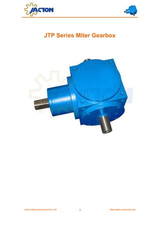
- 1. JTP Series Miter Gearbox Jacton Electromechanical Co.,Ltd 1 http://www.screw-jack.com
- 2. Contents General information ------------------------------------------------------------------------------- 3 Specifications --------------------------------------------------------------------------------------- 4 Selection Guide 1. Gearbox Series --------------------------------------------------------------------------------------- 5 2. Model -------------------------------------------------------------------------------------------------- 5 3. Gear Ratio--------------------------------------------------------------------------------------------- 5 4. Input & Output RPM ---------------------------------------------------------------------------------- 5 5. Shaft Arrangements And Direction Of Shaft Rotating ---------------------------------------------- 5-6 6. Mounting Position ------------------------------------------------------------------------------------- 6 Selection Examples -------------------------------------------------------------------------------- 7 Dimensions 1. Model JTP54 ------------------------------------------------------------------------------------------ 8 2. Model JTP90 ------------------------------------------------------------------------------------------ 9-10 3. Model JTP110 ---------------------------------------------------------------------------------------- 11-12 4. Model JTP140 ---------------------------------------------------------------------------------------- 13-14 5. Model JTP170 ---------------------------------------------------------------------------------------- 15-16 6. Model JTP210 ---------------------------------------------------------------------------------------- 17-18 7. Model JTP240 ---------------------------------------------------------------------------------------- 19-20 8. Model JTP280 ---------------------------------------------------------------------------------------- 21-22 Application Example ------------------------------------------------------------------------------ 23 Operation Manual ---------------------------------------------------------------------------------- 24-25 Frequently Asked Questions ------------------------------------------------------------------- 26 Company History ----------------------------------------------------------------------------------- 27 Contact Us -------------------------------------------------------------------------------------------- 28 Jacton Electromechanical Co.,Ltd 2 http://www.screw-jack.com
- 3. General Information Input power from 0.1 Kw to 157 Kw. Transmission torque from 9 Nm to 1299 Nm. 1:1 ratio, 1.5:1, 2:1, 3:1, 4:1, 5:1 gear reduction ratios, custom speed increaser 1:1.5, 1:2, 1:3 gear increasing ratio. Input and output speed from 10 rpm to 2000 rpm, custom higher speed 3000 rpm. High efficiency from 95% to 98%. Input and output shaft diameter from 11 mm to 60 mm. 12 types input and output shaft arrangements and rotation directions, shafts can be rotated clockwise and counterclockwise rotation directions. Solid shaft, hollow shaft and flange adapter are suitable, custom multiple spine keys. Horizontal mounting, overhung mounting or wall mounting are suitable. Two way gear box, three way gear box, four way gear box and five way gear box are suitable. Low backlash, quiet running, low temperature, high torque features. JTP series cubic miter gearbox structures include housing, miter gear, drive shaft bearing, shaft sealing ring, flange bearing, pinion shaft, output shaft, output shaft bearing, bearing cover. Miter Gear High purity rugged alloy steel material; Carburizing process, case hardened in pairs for intersecting shafts; Low noise with grinded spiral teeth; High torque with milled teeth; High rigidity and wear resistance Pinion Shaft and Output Shaft Hardened and tempered alloy steel material; Hanging heavy load capacity; With key and keyway; Customized stainless steel, chromium coated or other corrosion resistance painting; Customized spline shaft,shaft without key and keyway Housing High rigidity cast iron; Customized stainless steel, galvanic coating or corrosion resistance painting. Jacton Electromechanical Co.,Ltd 3 http://www.screw-jack.com
- 5. Selection Guide JTP – 90 – 1 2 1:1 – 1500R 3 4 – 1500R 5 – B – B3 6 7 1. Gearbox Series JT: “Jacton” brand P: P series miter gearbox 2. Model Model 54 90 110 140 Gearbox Sizes 54x54x54mm 90x90x90mm 110x110x110mm 140x140x140mm Model 170 210 240 280 Gearbox Sizes 170x170x170mm 210x210x210mm 240x240x240mm 280x280x280mm Before selecting gearbox frame no., please check corresponding model’s specifications 3. Gear Ratio Model 90 110 140 170 210 240 280 1:1 1:1 1:1 1:1 1:1 1:1 1:1 1:1 2:1 1.5:1 1.5:1 1.5:1 1.5:1 1.5:1 1.5:1 1.5:1 3:1 2:1 2:1 2:1 2:1 2:1 2:1 2:1 3:1 3:1 3:1 3:1 3:1 3:1 3:1 4:1 4:1 4:1 4:1 4:1 4:1 4:1 5:1 Gear 54 5:1 5:1 5:1 5:1 5:1 5:1 Ratio 4 & 5. Input & Output RPM Ratios 1:1 1.5:1 2:1 3:1 4:1 5:1 input Rpm output Rpm output Rpm output Rpm output Rpm output Rpm output Rpm 2000 2000 1333 1000 667 500 400 1500 1500 1000 750 500 375 300 1000 1000 667 500 333 250 200 750 750 500 375 250 187.5 150 500 500 333 250 167 125 100 250 250 167 125 83 62.5 50 50 50 33 25 17 12.5 10 6. Shaft Arrangements And Direction Of Shaft Rotating Note: input shaft and output shafts can be rotated in both forward and reverse directions. A: 2 way gearbox, input shaft clockwise rotation direction, right side output shaft anticlockwise rotation direction. B: 2 way gearbox, input shaft clockwise rotation direction, right side output shaft clockwise rotation direction. C: 2 way gearbox, input shaft clockwise rotation direction, left side output shaft clockwise rotation direction. D: 2 way gearbox, input shaft clockwise rotation direction, left side output shaft anticlockwise rotation direction. Jacton Electromechanical Co.,Ltd 5 http://www.screw-jack.com
- 6. E: 3 way gearbox, input shaft clockwise rotation direction, two output shaft clockwise rotation direction. F: 3 way gearbox, input shaft clockwise rotation direction, two output shaft anticlockwise rotation direction. G: 3 way gearbox, input shaft clockwise rotation direction, left side output shaft anticlockwise rotation direction, inline output shaft anticlockwise rotation direction. H: 3 way gearbox, input shaft clockwise rotation direction, left side output shaft clockwise rotation direction, inline output shaft anticlockwise rotation direction. L: 3 way gearbox, input shaft clockwise rotation direction, right side output shaft anticlockwise rotation direction, inline output shaft anticlockwise rotation direction. M: 3 way gearbox, input shaft clockwise rotation direction, right side output shaft clockwise rotation direction, inline output shaft anticlockwise rotation direction. N: 4 way gearbox, input shaft clockwise rotation direction, inline output shaft anticlockwise, two output shaft anticlockwise rotation direction. P: 4 way gearbox, input shaft clockwise rotation direction, inline output shaft anticlockwise, two output shaft clockwise rotation direction. 7. Mounting Position B3, C3, V3: horizontal mounting position B5, C5, V5: overhung mounting position B5, C5, V5: side wall mounting position Jacton Electromechanical Co.,Ltd 6 http://www.screw-jack.com
- 7. Selection Examples Load characteristics of each gearbox 50Nm, moderate load, working 8 hours/day continuously: i.e: driven machine factor f1=1.25, input speed=1000Rpm, ratio i=1:1 Calculated with the following formula, the torque required by each gearbox is Each gearbox required torque=50 x 1.25=62.5Nm No.1 Gearbox: No.1 gearbox carries its own torque of 62.5Nm and at the same time transmit torques to No.2 and No.3 gearboxes, so the total load is 62.5Nm+62.5Nm+62.5Nm=187.5Nm Check above 6th page specifications, JTP170 gearbox is selected No.2 Gearbox: Besides its own torque, No.2 gearbox has to transmit torque to No.3 gearbox, so the total load is: 62.5Nm+62.5Nm=125Nm Check above 6th page specifications, JTP140 gearbox is selected No.3 Gearbox: As only load C exists, torque large than 62.5Nm is acceptable. Check above 5th page specifications, JTP110 gearbox is selected Notes: 1. When i≠1, please make a choice of the input shaft. When pinion shaft acts as the input shaft, the machine is a gear reducer. When output shaft acts as the input shaft, it is an gear inceaser. The positions of the two shafts can not be changed once the mounting positions and dimensions are fixed. 2. When several gearboxes are connected for output, load capacity of the line shafting should be checked. Jacton Electromechanical Co.,Ltd 7 http://www.screw-jack.com
- 8. Dimensions Model JTP54 Drawing Jacton Electromechanical Co.,Ltd 8 http://www.screw-jack.com
- 9. Model JTP90 Solid Shaft Input and Solid Shaft Output Drawing Model JTP90 Solid Shaft Input and Hollow Shaft Output Drawing Jacton Electromechanical Co.,Ltd 9 http://www.screw-jack.com
- 10. Model JTP90 Flange Input and Solid Shaft Output Drawing Model JTP90 Flange Input and Hollow Shaft Output Drawing Jacton Electromechanical Co.,Ltd 10 http://www.screw-jack.com
- 11. Model JTP110 Solid Shaft Input and Solid Shaft Output Drawing Model JTP110 Solid Shaft Input and Hollow Shaft Output Drawing Jacton Electromechanical Co.,Ltd 11 http://www.screw-jack.com
- 12. Model JTP110 Flange Input and Solid Shaft Output Drawing Model JTP110 Flange Input and Hollow Shaft Output Drawing Jacton Electromechanical Co.,Ltd 12 http://www.screw-jack.com
- 13. Model JTP140 Solid Shaft Input and Solid Shaft Output Drawing Model JTP140 Solid Shaft Input and Hollow Shaft Output Drawing Jacton Electromechanical Co.,Ltd 13 http://www.screw-jack.com
- 14. Model JTP140 Flange Input and Solid Shaft Output Drawing Model JTP140 Flange Input and Hollow Shaft Output Drawing Jacton Electromechanical Co.,Ltd 14 http://www.screw-jack.com
- 15. Model JTP170 Solid Shaft Input and Solid Shaft Output Drawing Model JTP170 Solid Shaft Input and Hollow Shaft Output Drawing Jacton Electromechanical Co.,Ltd 15 http://www.screw-jack.com
- 16. Model JTP170 Flange Input and Solid Shaft Output Drawing Model JTP170 Flange Input and Hollow Shaft Output Drawing Jacton Electromechanical Co.,Ltd 16 http://www.screw-jack.com
- 17. Model JTP210 Solid Shaft Input and Solid Shaft Output Drawing Model JTP210 Solid Shaft Input and Hollow Shaft Output Drawing Jacton Electromechanical Co.,Ltd 17 http://www.screw-jack.com
- 18. Model JTP210 Flange Input and Solid Shaft Output Drawing Model JTP210 Flange Input and Hollow Shaft Output Drawing Jacton Electromechanical Co.,Ltd 18 http://www.screw-jack.com
- 19. Model JTP240 Solid Shaft Input and Solid Shaft Output Drawing Model JTP240 Solid Shaft Input and Hollow Shaft Output Drawing Jacton Electromechanical Co.,Ltd 19 http://www.screw-jack.com
- 20. Model JTP240 Flange Input and Solid Shaft Output Drawing Model JTP240 Flange Input and Hollow Shaft Output Drawing Jacton Electromechanical Co.,Ltd 20 http://www.screw-jack.com
- 21. Model JTP280 Solid Shaft Input and Solid Shaft Output Drawing Model JTP280 Solid Shaft Input and Hollow Shaft Output Drawing Jacton Electromechanical Co.,Ltd 21 http://www.screw-jack.com
- 22. Model JTP280 Flange Input and Solid Shaft Output Drawing Model JTP280 Flange Input and Hollow Shaft Output Drawing Jacton Electromechanical Co.,Ltd 22 http://www.screw-jack.com
- 23. Application Examples JTP Series Miter Gearbox is widely applied in screw jack lift system, printing press, plastic extruder, sewage auger, bonding equipment, metering auger, sewage agitator, newspaper conveyor, bottling equipment, material handling, web finishing, paper conveying, conveyor, cardboard box equipment, packaging, vertical pump drive, sand spreader, residential mower, snow blower, mining equipment, crane, agricultural, grain wagon, harvester, forage harvester, manure spreader, fertilizer spreader and sewage conveyor etc. Jacton Electromechanical Co.,Ltd 23 http://www.screw-jack.com
- 24. Operation Manual Please read this entire document prior to operating the miter gearbox. Miter gearbox failure or injury to operators may be caused by improper installation, operation or maintenance. Installation Miter gearboxs must be mounted on a rigid, structurally sound baseplate. Ensure that miter gearbox mounting pads rest evenly on the baseplate. The use of shims may be required to avoid housing distortion which could alter the gear mesh or cause premature bearing failure. The miter gearbox may be driven by direct coupling, flexible coupling, or V-belt drive. Couplers should require only a light force to install. The driveline must be accurately aligned within the equipment manufacturer's requirements to limit operating loads and minimize thrust loads on the miter gearbox shaft. V-belt drives must be mounted close to the housing to minimize excessive overhung loading which could result in early bearing or shaft failures. Sheaves must fit correctly. At installation, a tight forced fit could move the shaft from its normal position and cause internal damage. A loose fit could induce excessive vibration during operation and cause shaft damage or breakage. Warning When mounting the miter gearbox, the buyer is responsible to properly determine the quality or grade of fastener, thread engagement, load carrying capacity, and torque requirements. Warning The buyer is responsible to provide protective shields over all external rotating parts, couplers, or shaft extensions mounted on or with the miter gearbox. Protective clothing must be worn when installing or maintaining the miter gearbox and operating system. Initial operation should be carried out under no-load conditions. Before applying power to the miter gearbox installation, review the following: 1. Check tightness of mounting bolts. 2. Check for proper oil level in miter gearbox. 3. Be certain that tools, debris, etc., are clear from rotating parts. 4. Rotate shafts by hand. If they do not rotate freely, check for uneven mounting, coupling misalignment or excessive belt tension. If all tests are satisfactory, make connections to shafts, ensure that all safety devices are in place, and begin operation. Lubrication All miter gearboxes are factory tested prior to shipment. They include the correct amount of oil unless specified by the customer to be shipped dry. Shaft bearings are splash lubricated and partially submerged in oil when the miter gearbox is mounted horizontally. After installation, remove the dipstick and verify correct oil level. If no dipstick is provided, determine level by any appropriate method. In general, the oil level should be approximately half the depth of the miter gearbox (to the parting line) for horizontal mounting, or to the shaft centerlines, if mounted other than horizontally. Caution Prior to operation, make sure the miter gearbox contains the correct amount of oil. If under-filled or over-filled, damage to the miter gearbox or injury to personnel may result. Jacton Electromechanical Co.,Ltd 24 http://www.screw-jack.com
- 25. Approved Lubricants: For miter gearboxs operating in an ambient temp of –20 Deg. C and +85 Deg. C JTP series miter gearbox lubricant using liquid gear oil. When low speed less than 100Rpm, optional grease lubricant Caution Donot combine synthetic with non-synthetic oils in the miter gearbox. Maintenance Warning Disconnect power prior to any maintenance and do not bypass or inactivate any safety or protective device. Lock out and tag the power supply to prevent unexpected application of power. Routinely inspect mounting bolts, couplers,or other power transmitting devices to ensure all parts are firmly anchored.Keep shafts and vent plugs (when included) clean to prevent foreign particles from entering seals or housing. Inspect daily for any oil leaks and any unusual noises. Inspect weekly for end play in shafts. Inspect belt drive tension after the first ten hours of operation and periodically thereafter. Check the oil level every 24 hours of operation. In the beginning to change the oil when the miter gearbox has been in service for two weeks or 100 ~ 200 hours. Routine oil change intervals will vary for each particular installation depending on the severity of the environment. Normal changes should occur half ~ 1year or 1000 ~ 2000 hours of operation. The longest life at continuous service will be realized when the oil temperature does not exceed +85 deg. C. For oil substitutions, or for high input speeds, contact Jacton engineers. Warning Donot change or add oil while the miter gearbox is running. Damage to the miter gearbox or injury to personnel may result. The miter gearbox housing, oil, plugs, and associated components may reach high temperatures and cause severe burns. Use extreme care when servicing the miter gearbox. Trouble Shooting Jacton Electromechanical Co.,Ltd 25 http://www.screw-jack.com
- 26. Frequently Asked Questions How Do I Know Which Shaft Of Miter gearbox Is As Input Shaft? When using a 1:1 ratio gearbox ,it does not matter which shaft is used as the input shaft. Normally, X-shaft is input shaft, Y-shaft is output shaft. For other reduction gear ratios input shaft is same as 1:1 ratio gearbox, but for increasing gear ratios input shaft, which is Y-shaft is input shaft, X-shaft is output shaft. Can I Use Miter gearbox As Speed Increaser? All miter gearbox can be used as speed increaser, by inputting on the output side of the gearbox, however it is important to check whether the miter gearbox can handle the power and speed. When using as an increaser, the input speed does not exceed the specifications recommended maximum speed. Special gearbox is available where the pinion can be put on the through shaft so that two output shaft increase the speed. Are Miter gearboxes Supplied Filled With Gear Oil? Yes, all miter gearboxes are filled gear oil prior to shipment, customers can install them and use them directly. Note: for low speed applications (100 rpm input speed and below) miter gearboxes may be recommended to have grease lubrication. How Often Should I Change Gear Oil In The Miter gearbox? Check the gear oil level every 24 hours of operation. In the beginning to change the gear oil when the miter gearbox has been in service for two weeks or 100 ~ 200 hours. Routine oil change intervals will vary for each particular installation depending on the severity of the environment. Normal changes should occur half ~ 1year or 1000 ~ 2000 hours of operation. The longest life at continuous service will be realized when the oil temperature does not exceed +85 deg. C. For oil substitutions, or for high input speeds, contact Jacton engineers. How Transmission Efficiency Of Miter gearbox? The miter gearbox transmission efficiency up to 98% Jacton Electromechanical Co.,Ltd 26 http://www.screw-jack.com
- 27. Company History In 1997, Established Jacton Hardware Fabrication Plant, mainly processing kinds of hardware following customers requirements. Occupied 500 square meters. In 2000, Established domestic sales department, started to develop local market, mainly processing gear transmission parts such as worm and worm gear, acme threads screw, square threads screw and acme lead screw nut. Meanwhile, sales also sell straight miter gear and spiral miter gears for customers. In 2002, According to some regular customers of steel plants and machines manufacturers, which used Taiwan screw jacks and miter gearboxes, due to long delivery and high price, would affect the normal operations. Jacton Hardware Fabrication Plant started to processing JT acme screw jack and JT miter gearbox following above customers samples. In 2003, Established engineering department, research and development others models of JT acme screw jack and JT miter gearbox, and draw some factory production drawings and local sales' customers drawing with 2d autocad software. In 2005, According to local market demands, Jacton Hardware Fabrication Plant is committed to research and development JB/T8809-1998 standard JTW worm screw jack, JTM machine screw jack, JTB ball screw jack and JTP cubic body miter gearbox. In 2006, Because of local markets fiercely competitive. Established Hongkong office-Jacton International Limited with own US dollars and EURO account. Established international sales department, focused on overseas markets. Meanwhile, "JACTON" as company only brand. In 2008, According to intl sales market report, cubic body screw jacks and another type cubic body miter gearboxes are very popular in Europe and America markets. After managements meetings, we started to develop JTC cubic screw jack, JTS high speed miter gear jack, JTV cubic body miter gearbox and JTA corrosion resistance aluminium body miter gearbox. In 2009, Jacton Hardware Fabrication Plant extension, occupied 5000 square meters. Company improves the processes and products through technology investment, brings in advanced technology, production and testing equipment. In 2010, Jacton Hardware Fabrication Plant Passed ISO9001:2008 quality management system, we are strictly implement the work flow of ISO9001:2008 certifications, which ensures oversea and local customers are satisfaction with our screw jacks and miter gearboxes and fast delivery time. In 2012, In order to facilitating management, according to management decisions, sales department and design department moved to Taibao business building. Meanwhile, Jacton Hardware Fabrication Plant changed to be Dongguan Jacton Electromechanical Co.,Ltd. Jacton Electromechanical Co.,Ltd 27 http://www.screw-jack.com
- 28. Contact Us Jacton Electromechanical Co.,Ltd Jacton Electromechanical Co.,Ltd (Head Quarters) (Sales Dept. & Design Dept.) 1&2 Floors, Building F, Baisheng Industrial 1118, Taibao Business Building, No.1 Areas, Langwei Rd, Xinan, Changan, Dongguan, No.34, Yongjun Road, Datang, Dalingshan, Dongguan, Guangdong, China Guangdong, China Phone: 86 769 81585810 Phone: 86 769 81585852 Mobile: 86 189 25569548 Fax: Jacton International Limited Contact Us (Hong Kong Branch) General Enquiries: sales@screw-jack.com 86 769 81620195 jactonjack@gmail.com Office 17,9/F.,Tower A,New Mandarin Online Skype: jactonjack (Warren) Tsimshatsui,Kowloon,Hongkong Online Skype: jactongearbox (Abby) Tel: 852-2793-5511 Website: http://www.screw-jack.com Fax:852-3590-2333 Urgently required, please directly make a call Plaza,No.14,Science Museum Road, to Warren +86 13532830851 Jacton Electromechanical Co.,Ltd 28 http://www.screw-jack.com