
Recommended
More Related Content
Viewers also liked
Viewers also liked (18)
Similar to Overview of CBM exploration and produced water treatment
Similar to Overview of CBM exploration and produced water treatment (20)
Overview of CBM exploration and produced water treatment
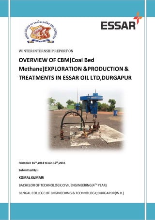
- 1. WINTER INTERNSHIP REPORTON OVERVIEW OF CBM(Coal Bed Methane)EXPLORATION &PRODUCTION & TREATMENTS IN ESSAR OIL LTD,DURGAPUR From Dec 16th,2014 to Jan 10th,2015 Submitted By:- KOMAL KUMARI BACHELOROF TECHNOLOGY,CIVIL ENGINEERING(4TH YEAR) BENGAL COLLEGEOF ENGINEERING & TECHNOLOGY,DURGAPUR(W.B.)
- 2. Page | 2 CANDIDATE’S DECLARATION I hereby, declare that the work which is being presented in this winter Training entitled ”OVERVIEW OF CBM EXPLORATION& PRODUCTION AND TREATMENTS ”in partial fulfilment of the requirements for the award of degree of Bachelor of Technology in Civil Engineering submitted in the department of Civil Engineering, B.C.E.T, Durgapur is an authentic record of my own work, carried out during the period from Dec 16th , 2014 to Jan 10th ,2015 under the supervision of Mr. SANJAY KHADAYATE ,JGM,Infrastructure,Water Management) The matter embodied in this winter Training report has not been submitted by me for the award of any other degree. Date:10.01.2015 Place:Durgapur (KOMAL KUMARI) B.Tech(Forth year),civil engineering Department of Civil Engineering, B.C.E.T, Durgapur-12| West Bengal| This is to certify that abovestatement made by the candidate is correct to the bestof my knowledge. Mr. SANJAY KHADAYATE JGM,Infrastucture,Water Management Essar Oil Ltd. (E&P Division) Webel ITPark, Surya Sen Sarani, Near Gandhi More, Durgapur-713208|WestBengal|India|
- 3. Page | 3 ACKNOWLEDGEMENT I would like to express my heartily gratitude to Mr.SANJAY KHADAYATE Mr.RAMCHANRA NAMJOSHI , of this organization, for giving me such a wonderful opportunity to do an internship with this organization and become aware of all the practises and procedures carried out in this organization. For me it was a unique experience being a part of this organization. It helped me a lot in understanding the operational behaviour that is an indispensable part of an organization. Besides being from Civil Engineering field, I got a lot of things to learn regarding the coal gas exploration and production which I think will surely prove to be helpful for me on my profile and knowledge part. I would also like to thank Ms. MANIDIPA MAJI , Mr. SUSHIL MISHRA & Mr.SUDHIR KANNA who as a guide helped me a lot in making this internship a success for me. I also liked the employees and the strict discipline protocol carried out in the office of Webel- IT Park. With their patience, co-operation and openness they created an enjoyable working environment for me. KOMAL KUMARI B.Tech(Civil Engineering) Bengal College Of Engineering & Technology, Durgapur
- 4. Page | 4 CONTENTS Acknowledgement 3 Abstract 5 1. The Organization Essar …………………………………………………….6 2. Operational ProjectMap ………………………………………………….7 3. Environmental ImpactAssessment……………………………………8 4. Standard Parameters ……………………………………………………….13 5. Introduction of CBM…………………………………………………………14 6. Layout of produced water………………………………………………..15 7. Site preparation of production well And well pad construction ………………………………………………. 16 8. What is ReverseOsmosis …………………………………………………22 9. Why R.O is Opted for treatment of produced water ………….23 10.Low PressureReverseOsmosi…………………………………………...26 11.Sea Water ReverseOsmosis ………………………………………………29 12.ZLD(Upcoming project) ……………………………………………………..35 13.CBM Gas Processing ………………………………………………………….36 14.Hydraulic Fracturing ………………………………………………………….41 15. Conclusion………………………………………………………………………… 16.References ………………………………………………………………………..
- 5. Page | 5 ABSTRACT Coal Bed Methane (CBM) is a rapidly emerging alternative energy source in many countries where vast amount of coal resource are found in the rocks of many different geologic areas. This natural gas is either stored in micro-pores or fractures of Coal Bed or escapes and migrates into adjacent porous and permeable sandstones reservoirs. This gas is mainly methane that resulted from Coalification (fermentation and maturation) of peat deposits over millions of years. The term refers to methane adsorbed into the solid matrix of the coal. It is called 'sweet gas' because of its lack of hydrogen sulfide. The presence of this gas is well known from its occurrencein underground coal mining, where it presents a serious safety risk. Coalbed methane is distinct from a typical sandstone or other conventional gas reservoir, as the methane is stored within the coal by a process called adsorption. The methane is in a near-liquid state, lining the inside of pores within the coal (called the matrix). The open fractures in the coal (called the cleats) can also contain free gas or can be saturated with water. Unlike much natural gas from conventional reservoirs, coalbed methane contains very little heavier hydrocarbons such as propane or butane, and no natural-gas condensate. It often contains up to a few percent carbondioxide. Some coal seams, such as those in certain areas of the Illawarra Coal Measures in New South Wales, contain little methane, with the predominant coal seam gas being carbondioxide.
- 6. Page | 6 The Organization Essar The Raniganj Block is located in the Damodar Valley coal field in the Raniganj region of West Bengal. Essar Oil entered into a 35-year contract with the Government of India for the exploration and production of CBM in the Raniganj Block in July 2002. Sourcing CBM requires much less land than mining for coal or petroleum, thus reducing environmental impact and minimizing overall land footprint. The technology Essar Oil uses for the exploitation of the CBM reduces the impact further. Essar Oil has adopted directional drilling technology, also known as horizontal drilling, where one well-head can house up to four directional wells. The company's largest current CBM operation is at Raniganj in West Bengal. The total CBM acreage of the Raniganj CBM gas field is 500 sqkms. It currently produces about 325415 SCM (standard cubic meters) of gas per day. Essar Oil has received phase-3 environmental clearance from the Government of India's Ministry of Environment and Forests for its Raniganj gas field operations, which allows it to drill up to 650 wells. Currently, 194wells have been drilled, of which 134 are in production, with the balance in dewatering stage. The drilling program is now being accelerated. Its recently opened E&P (exploration and production) headquarters at Durgapur is the nerve centre of all these operations, housing a centre of excellence that manages the advanced data gathering, analysis, interpretation, log co-relation and geo-modelling and other analytics required for all its CBM and other gas blocks
- 7. Page | 7 Operational Project map: A no. of surveys namely magnetic surveys and other surveys are conducted over long years in order to identify the different regions as a coal bed. The coal bed is later divided into a no. of coal blocks and then the bidding is opened for different companies willing to acquire the coal blocks for their business setup purposes. ESSAR won the bid of the Raniganj CBM Coal Block bid in the year 2002 and now it is conducting its exploration and production operations at the site obtained.
- 8. Page | 8 ENVIRONMENTAL IMPACT ASSESSMENT ( EIA ) For a nation to progress socially and economically, developmental in different fields is essential. While development helps in raising the standards of life, it also has some side effects which are mainly responsible for environmental deterioration. In post-independence period, India went ahead with several development projects and showed rapid industrial growth. However, we did not pay much attention to the pollution problem at that time. The total insensitivity on ecological and environmental aspects on the part of our government and policy makers until recently has put a huge backlog of negative environmental impacts, which have to be set right. It is very important, therefore, to know the environmental impacts of various types of developmental activities. The cause and effect relationships of the projects and their impact analysis need to be done systematically. Environmental Impact Assessment (EIA) is a procedure to plan some developmental activity with well-defined environmental goals so that damage due to the activity both during developmental stage and production stage have minimum impact on the natural system and the population in the area. The National Environmental Protection Agency (NEPA) U.S.A. in 1969 first of all provided the guidelines for environmental impact assessment through Council for Environmental Quality (CEQ). In India, the gazette notification on EIA was issued in 1994 vide which the Ministry of Environment and Forests provided guidelines for project proponents to have EIA and prepare an Environmental Impact Statement prior to clearance the project. Goals of EIA:- (i) To fulfill the responsibilities towards the coming generations as trustees of environment. (ii) To assure safe, healthy, productive, aesthetically as well as culturally pleasing surroundings. (iii) To provide widest range of beneficial uses of environment without degradation or risk to health. (iv) To preserve historical, cultural and natural heritage. (v) To achieve a balance between population and resource use for a good standard of living. (vi) To ensure sustainable development with minimal environmental degradation. The following points are usually incorporated while preparing the Environmental Impact Statement (EIS): Effect on land including land degradation and subsistence. Deforestation and compensatory Afforestation. Air pollution and dispersion along with possible health effects. Water pollution including surface water and ground water pollution. Noise pollution. Loss of flora and fauna. Socio-economic impacts including human displacement, cultural loss and health aspect. Risk analysis and disaster management. Recycling and reduction of waste. Efficient use of inputs including energy and matter.
- 9. Page | 9 EIA is done with an aim to select the best alternative through which adverse impact on the environment can be nullified or minimized without compromising with the economic and social benefits of the developmental project. The alternatives can be in three ways: (i) Alternative technologies providing options with maximum energy efficiency and minimal wastage. (ii) Alternative mitigating or controlling mechanisms through which recycling of by- products or reduction of emissions can take place. (iii) Alternate phasing to work out if phasing of the project is possible instead of one stroke development to avoid drastic impact. However, besides these alternatives, the most important alternative taken into consideration in EIA is the impact assessment at alternative sites i.e., which of the site I or II or III located in different natural area would have the least impact of the development project, and that site is selected for the development project. Thus, the main purpose of EIA is precisely to estimate the type and level of damage caused to natural environment in a well-defined time scale so that remedial measures can be initiated on those aspects requiring action at the right time. Methodology The basic steps followed in EIA are screening, scoping, base line data, impact identification, prediction, evaluation, mitigation, EIS preparation, review and environment audit. (i) Screening is done to see whether the project needs an EIA for clearance or not. Further, there are some prohibited areas where no development project is allowed. (ii) Scoping involves determination of the extent of EIA required for the project. (iii)Public consultation concern in the environmental impacts of the project or activity arens of local affected persons and others who have stake ascertained.Only locals can attend the PC. (iv)Appraisal means the detailed scrutiny by EAC(Expert Appraisal Committee)/SEAC(State Level Expert Appraisal Committee) to recommend to MoEF for grant of environmental clearance. Environmental Impact Statement (EIS): It should include the following five major aspects (a) The environmental impact of the proposed action. (b) The adverse impact that cannot be avoided if the development occurs. (c) Alternatives to the proposed action. (d) Relation between the local short-term use of human environment and maintenance of long-term production. (e) Irreversible changes in resources. EIS is to be written in the format provided by the MOEF or CEQ as per their guidelines. Environmental Audit: EIA must be followed by a suitable environmental audit or environmental management system (EMS).Environmental impact auditing involves comparison of the impacts predicted in the EIS with those actually occurring after the implementation to assess whether the impact prediction performs satisfactorily.
- 10. Page | 10 In order to maximize optimal utilization of natural resources and minimization of emission/discharge of pollutants/waste products in environment and reuse/recycling measures, environmental auditing has been introduced by Ministry of Environment & Forests and the Pollution Control Boards. An annual statement is required to be submitted by Project Authorities to the Pollution Control Board reflecting their achievements made during the year on above mentioned aspects. Environmental auditing thus helps to safeguard the environment and assists in complying with local, regional and national laws and regulations, with the company’s policy and with the environmental standards. An EIS publication sequence is prescribed by law. First, a draft EIS (DEIS) is issued by the appropriate federal agency. After mandated public hearings and incorporation of comments, the federal agency issues a final EIS (FEIS). A Record of Decision (ROD), which includes the final decision about the project, the alternative chosen, and any value judgments, is also issued. The purpose of environmental assessments was not to justify or fault projects, but to introduce environmental factors into the decision-making machinery and have them discussed in public before decisions about a project are made. An EA or EIS is usually organized into the following sections: Introduction The introduction provides an overview of the proposed project, alternative actions, and the assessment methods that will be used. It includes a statement of purpose: why the assessment is being done. It often includes a summary of the most critical and important results of the assessment. The introduction can often serve as an executive summary of the EIA or EIS. Description of the Proposed Action and Alternatives This section describes the proposed project and all of the alternatives that need to be considered, including the “no action” alternative. The last is a description of projections of future scenarios if the proposed project is not done. All possible alternatives need not be included; inclusion depends on the project being undertaken. For example, the EIS for the proposed high-level radioactive waste repository at Yucca Mountain, NV, was not required to consider alternate waste repository sites. Description of the Environment Affected by the Proposed Action This description is best organized by listing environmental parameters that could be impacted by the proposed alternative, grouping them into logical sets. One listing might be: Ecology
- 11. Page | 11 -Species and populations -Habitats and communities -Ecosystems -Wetland Aesthetics -Land -Air -Water -Biota -Human-made objects -Objects of historical or cultural significance Environmental Pollution and Human Health -Water -Air -Land -Noise Economics -Jobs created or lost -Property values -Jobs One procedure is to fist estimate the ideal or natural levels of environmental quality (without anthropogenic pollution) and take a ratio of the expected condition to the ideal. Ethical Considerations A properly done environmental impact assessment is independent of any ethical system and is value-free. However, ethical questions can arise in formulating a record of decision based on an environmental assessment. Some of these questions are: Is it ethical to limit resource extraction, with its concomitant environmental damage, by raising the resource price and thereby limiting its use to those who can afford it? Is it ethical to eliminate jobs in an area in order to protect the environment for a future generation? Conversely, is it ethical to use up a resource so that future generations do not have it at all? Given limited financial resources, is it ethical to spend millions mitigating a High consequences impact that is extremely unlikely to occur (a low- probability, High consequence event)? Is it ethical to destroy a watershed by providing logging jobs for 50 years? Conversely, is it ethical to close down a lumber mill, eliminating jobs for an entire small community, in order to save an old-growth forest?
- 12. Page | 12 CONCLUSION Engineers are required to develop, analyze, and compare a range of solutions to any given environmental pollution problem. This range of alternatives must be viewed in terms of their respective environmental impacts and economic assessments. A nagging question exists throughout any such viewing: Can individuals really measure, in the strict “scientific” sense, degradation of the environment? For example, can we place a value on an unspoiled wilderness area? Unfortunately, qualitative judgments are required to assess many impacts of any project.
- 13. Page | 13 STANDARD PARAMETERS PRODUCED WATER Parameter Unit Onshore Discharge Standards pH 5..5-9.0 Total Suspended Solids mg/l 100 Total Dissolved Solids mg/l 2100 Turbidity mg/l $ Acidity as CaCO₃ mg/l $ Alkalinity as CaCO₃ mg/l $ Chlorides as Cl mg/l 600 Total Hardness as CaCO₃ mg/l $ Sulphates as SO₄ mg/l 1000 DO mg/l $ BOD mg/l 30 COD mg/l 100 Oil & Grease mg/l 10 Phenolic Comounds mg/l 1.2 Sulphides as S mg/l 2 Flourides mg/l 1.5 ToTal Chromium(as Cr) mg/l 1 Zinc as Zn mg/l 2 Copper as Cu mg/l 0.2 Arsenic as As mg/l $ Lead as Pb mg/l 0.1 Mercury as Hg mg/l 0.01 Sodium Absorption Ratio(SAR) $ Electrical Conductivity at 25˚C us/cm $ Silica mg/l 30 NOISE Permissible Limit as per CPCB Day Time 55 Night Time 45 AIR PARAMETER UNIT NAAQS Limit Particulate matter(PM2.5) µg/m³ 60(24 hrs) Particulate matter10(PM10) µg/m³ 100(24 hrs) Nitrogen Dioxide (NO₂) µg/m³ 80(24 hrs) Sulphur dioxide (SO₂) µg/m³ 80(24 hrs) THC as Methane mg/m³ ‒ VOCs µg/m³ ‒ Ammonia (NH₃) µg/m³ 400 Carbon Monoxide(CO) mg/m³ 2 (8 hrs) Ozone(O₃) µg/m³ 100
- 14. Page | 14 INTRODUCTION OF CBM:- CBM stands for COAL BED METHANE which is an unconventional natural gas mainly METHANE (CH4) with small amount of other hydrocarbon and non hydrocarbon gases contained in coal seams as a result of chemical and physical processes known as coalification. The term refers to methane adsorbed into the solid matrix of the coal. It is called 'sweet gas' because of its lack of hydrogen sulphide. The presence of this gas is well known from its occurrence in underground coal mining, where it presents a serious safety risk. Coal bed methane is distinct from a typical sandstone or other conventional gas reservoir, as the methane is stored within the coal by a process called adsorption. The methane is in a near-liquid state, lining the inside of pores within the coal (called the matrix). The open fractures in the coal (called the cleats) can also contain free gas or can be saturated with water.CBM is a gas that is “adsorbed” onto coal by pressure of water in coal seams deeper than 100 m. CBM is preffered to obtain at a depth of more than 500 m so that the natural ground water source should remain unaffected. The coal seams have large internal surfaces, the coal seams can store methane on the order of six to seven times more than the equivalent volume of rock in conventional gas reservoir. Coal bed methane exists as a monomolecular layer, adsorbed on the internal surface of coal matrix. During the first stage, as pressure drops, the reservoir dewaters and methane production increases. During second stage, improving gas/water relative permeability and desorption counterbalances the permeability loss from formation compaction. The third stage mirrors conventional gas production as pressure in reservoir decline.
- 15. Page | 15 LAYOUT OF THE PRODUCED WATER WELL PAD RAWWATER GAS R.O PLANT PRODUCT REJECT KUNUR NALLA ECL COAL MINES(DUST SUPRESSION) etc.
- 16. Page | 16 SITE PREPARATION OF PRODUCTION WELL AND WELL PAD CONSTRUCTION SITE PREPARATION:- Production well site preparation primarily entrail the removal and storage of the top soil followed by cutting, grading and levelling works. Further the approach roads to the new/existing well sites need to be strengthened and permanent roads need to be constructed to enable access to the proposed production well sites and facilitate transportation of drilling rigs and heavy vehicular movement. The proposed roads will primarily be built using locally available materials and slag. Basically cement, sand and earth fill materials is utilised for the site preparation of production wells, GGS and MCS. While preparing for production wells, it includes construction of HDPE(High Density Poly Ethylene)lined pit at each well for temporary storage and disposal of drill cutting and formation water. PRODUCTION WELL DRILLING:- The production wells are drilled with a combination of low capacity rigs for surfacesection and higher capacity rigs for the coal bearing section. For drilling coal seams at lower target depth, air drilling rig will be deployed while for deeper & directional wells, water based mud drilling with rotary drilling rigs will be utilized. Directional wells with angle upto 30° are planned to be drilled from single well site to minimize the land requirement. Directional drilling will be conducted where vertical drilling is difficult or not possible. DRILL CUTTINGS:- Drill cuttings generated from air/mud drilling will be collected and separated using a solid control system and temporarily stored on site in HDPE lined pit.
- 17. Page | 17 FORMATION WATER:- During drilling operation some formation water is also likely to be generated in limited quantities from the water bearing zones. The analysis results of the water showed that the water is exceeding the CPCB discharge standard for TDS, Sulphide &Sodium content. The formation water will be temporarily stored in pits and adequately treated prior to its discharge to nearby streams or surface bodies. DEVELOPMENT OF PRODUCTION WELL COMPLETION PROGRAM:- Well completion program usually last for 10-15days including perforation of wells, steel casing, fracturing the producing formation hydro-structure & installation of a series of valves & fittings at well head, which in turn connected to the production tubing and down hole pumps. PERFORATING WELL STEEL CASING:- The casing and the cement will be perforated at the target formation to create holes into the production zones by the use of TNT (Tri Nitro Toluene). The production testing will be done by perforating the target coal seam based on response from logs open holes. The pipes must be perforated for gas to flow into the well bore. The well will be then tested by dewatering the coal seam through submersible/PC pumps production of CBM gas will be taken through a test separator & reservoir studies will be performed depending on the response from the well. PRODUCTION TUBING AND DOWNHOLE PUMPS INSTALLATION:- Installation of production tubing and down hole pump is the final completion of work. Both equipment valves & fittings installed on the well head. Even though the produced water & gas can flow into the casing after it is perforated a small dia pipe called tubig is placed into the well to serve as a way for produced water to enter into the surface.
- 18. Page | 18 HYDRAULIC FRACTURING:- Itis supposed to stimulate the production by increasing the permeability of the formation. In Hydraulic Fracturing “frac fluid”(water from toxic additives) will be pumped under extremely high pressure downwards through the casing or tubing & bring out through the perforation in the casing. As a result, the pressurized fluid will enter the productive formation and fractures it. DEVELOPMENT & PRODUCTION WELL TESTING PROGRAM:- DEWATERING STABLE PRODUCTION STAGE DECLINE STAGE STAGE RATE METHANE WATER TIME Hydraulic Fracturing of coal seams will be followed by well testing program that involves dewatering of the coal seams saturated with water to achieve optimal gas production is considered to be an important operation essential to the success of the wells. Dewatering coal seam reduces the formation pressure &allows gas to be deabsorbed from the coal matrix causing it to the flow to the well bore. During initial dewatering phase gas production increases steadily. While the amount of water decreases. Eventually production levels begins to resemble a conventional gas well and the gas reserve gradually declines until it is no longer economical. SURFACE FACILITIES:- Surface production facilities installed at the well site will include a collection of valve, gas & water separation system, gas metering facilities etc.
- 19. Page | 19 SEPARATOR:- The CBM gas is then separated from the produced water by a two phase separator located at the surface of each well site to yield gas and produced water. Following separation the is metered & routed through gas gathering pipelines for transport to GGS. Separated produced water will be channelized to onsite pits for temporary storage. The produced water so stored will be adequately to its disposal at any natural drainage channels or usage for agriculture. The dewatering pumps installed at well site have the provision to switch off by SCADA telemetry system from control room. GAS WATER WELLS GAS + WATER SEPARATOR GAS LINES WATER TANKS PUMPS GAS GATHERING STATIONWATER LINES CUSTOMER END R.O.PLANT
- 21. Page | 21
- 22. Page | 22 WHAT IS REVERSE OSMOSIS? Reverse osmosis (RO) is a water purification technology that uses a semi-permeable membrane. This membrane technology is not properly a filtration method. In reverse osmosis, an applied pressure is used to overcome osmotic pressure, colligative property, that is driven by chemical potential, a thermodynamic parameter. In the normal osmosis process,the solvent naturally moves from an area of low solute concentration (high water potential), through a membrane, to an area of high solute concentration (low water potential). The movement of a pure solvent is driven to reduce the free energy of the system by equalizing solute concentrations on each side of a membrane, generating osmotic pressure. Applying an external pressure to reverse the natural flow of pure solvent, thus, is reverse osmosis. Reverse osmosis is most commonly known for its use in drinking water purification from seawater, removing the salt and other effluent materials from the water molecules.
- 23. Page | 23 WHY R.O. IS OPTED FOR TREATMENT OF FORMATION WATER? RO process was suggested for the draw solution of formation water because of its high efficiency and applicability for a wide range of ionic solution treatments. Reverse osmosis can remove many types of molecules and ions from solutions, and is used in the production of potable water. The result is that the solute is retained on the pressurized side of the membrane and the pure solvent is allowed to pass to the other side. This membrane should not allow large molecules or ions through the pores (holes), but should allow smaller components of the solution (such as the solvent) to pass freely. The process is similar to other membrane technology applications. However, key differences are found between reverse osmosis and filtration. The predominant removal mechanism in membrane filtration is straining, or size exclusion, so the process can theoretically achieve perfectexclusion of particles regardless of operational parameters such as influent pressure and concentration. Moreover, reverse osmosis involves a diffusive mechanism, so that separation efficiency is dependent on solute concentration, pressure, and water flux rate. It is also used to clean effluentand brackish groundwater. The effluent in larger volumes (more than 500 m3 /d) should be treated in an effluent treatment plant first, and then the clear effluent is subjected to reverse osmosis system. Treatment cost is reduced significantly and membrane life of the reverse osmosis system is increased. Reverse osmosisprocess for water purification does not require thermal energy. Flow-through reverse osmosis systems can be regulated by high-pressure pumps.
- 24. Page | 24 PROCESS DESCRIPTION:- The water obtained at the well pad is transported to the R.O. plant through pipelines or tankers for the treatment process. The water collected from the well pad also called as formation water has very high TDS(Total Dissolved Solids) value. As per the environment law we cannot discharge water with TDS value more than 2100 mg/l. The water obtained during the process of Coal Bed Methane Exploration has TDS value around 30,000 mg/l. Thus, treatment of formation water is mandatory. To reduce the TDS value R.O. process is used. First of all formation water is collected in a pit called as raw water pit. From that pit water is sent to the filtration tank through pumps. Then water is sent to L.P.R.O(Low Pressure Reverse Osmosis)Plant Or simply R.O.(Reverse Osmosis)Plant. Here we can see that water is first sent to the filtration tank then to the R.O. plant as because water can contain many different types of contaminants that decrease the operating efficiency of our water treatment systems. Here custom microfiltration filters are provided that integrate with the current water treatment solutions or are a part of an entirely new water treatment system. In filtration process, a membrane is provided which removes contaminants from a fluid by micro-porous membrane. The membrane pore size ranges from .1 to 10 micrometres.These filters are porous and allow water, monovalent species (Na+, Cl-), dissolved organic matter, small colloids and viruses through but do not allow particles, sediment, algae or large bacteria through. Traditional filter systems may also provided which use graded silica sand filter media. Since the sand grains all have about the same density, larger grains lay toward the bottom of the filter bed and finer grains lay at the top of the filter bed. As a result, filtration occurs only within the first few inches of the finer grains at the top of the bed. A depth filter has four layers of filtration media, each of different size and density which allows it to filter water more efficiently.
- 25. Page | 25 FIG: FLOW DIAGRAM OF R.O.PROCESS AT G.G.S.1 RAW WATER PIT L.P.R.O PRODUCT REJECT SWRO REJECT
- 26. Page | 26 Low Pressure Reverse osmosis Systems After filtration the water is sent to the R.O. plant. Before entering into the membranes of R.O. system, water is again passed through cartridge filters. A cartridge filter is a filter that uses a barrier/ sift method in order to clean sediments and harmful solids out of water. Some of these filters are made to stop it microscopic items and others are made simply to stop the major solids from entering a system. The cartridge filter is usually a cylindrical object, though in some cases it can look flat, much like an air filter. The shape of the cartridge filter is most dependent on its location. Then the water is sent to the R.O. system. At GGS1 two LPRO is used with capacity 700cum/day each.DEW is the company of which L.P.R.O is used. The factors that affect the performance of a Reverse Osmosis System are: Incoming water pressure Water Temperature Type and number of total dissolved solids (TDS) in the tap water The quality of the filters and membranes used in the RO System DIAGRAM OF A REVERSE OSMOSIS MEMBRANE:-
- 27. Page | 27 Basic components common to all Reverse Osmosis Systems: 1. Water Line Valve: Valve that fits onto the water supply line coming from the filtration tank. The valve has a tube that attaches to the inlet side of the RO pre filter. This is the water source for the RO system. 2. Pre-Filter (s): Water from the water supply line enters the Reverse Osmosis Pre Filter first. There may be more than one pre-filter used in a Reverse Osmosis system. The most commonly used pre-filters are sediment filters. These are used to remove sand silt, dirt and other sediment. Additionally, carbon filters may be used to remove chlorine, which can have a negative effect on TFC (thin film composite) & TFM (thin film material) membranes. Carbon pre filters are not used if the RO system contains a CTA (cellulose tri-acetate) membrane. 3. Reverse Osmosis Membrane: The Reverse Osmosis Membrane is the heart of the system. The most commonly used is a spiral wound of which there are two options: the CTA (cellulose tri-acetate), which is chlorine tolerant, and the TFC/TFM (thin film composite/material), which is not chlorine tolerant. 4. Post filter (s): After the water leaves the RO storage tank, but before going to the RO faucet, the product water goes through the post filter (s). The post filter (s) is generally carbon (either in granular or carbon black form). Any remaining tastes and odours are removed from the product water by post filtration. 5. Automatic Shut Off Valve (SOV): To conserve water, the RO system has an automatic shutoff valve. When the storage tank is full (this may vary based upon the incoming water pressure) this valve stops any further water from entering the membrane, thereby stopping water production. By shutting off the flow this valve also stops water from flowing to the drain. Once water is drawn from the RO product i.e. the clear water with TDS less than 500ppm, the pressure in the tank drops and the shut off valves opens, allowing water to flow to the membrane and waste-water (water containing contaminants) to flow down the drain. 6. Check Valve: A check valve is located in the outlet end of the RO membrane housing. The check valve prevents the backward flow or product water from the RO storage tank. A backward flow could rupture the RO membrane. 7. Flow Restrictor: Water flow through the RO membrane is regulated by a flow control. There are many different styles of flow
- 28. Page | 28 controls. This device maintains the flow rate required to obtain the highest quality drinking water (based on the gallon capacity of the membrane). It also helps maintain pressure on the inlet side of the membrane. Without the flow control very little drinking water would be produced because all the incoming tap water would take the path of least resistance and simply flow down the drain line. The flow control is located in the RO drain line tubing. 8. Storage Tank/Pit: The standard RO storage tank holds up to 2.5 gallons of water. A bladder inside the tank keeps water pressurized in the tank when it is full. At GGS1 the capacity of the storage pit is approx 1370 cum. 9. Drain line: This line runs from the outlet end of the Reverse Osmosis membrane housing to the drain. This line is used to dispose of the impurities and contaminants found in the incoming water source ( formation water). The flow control is also installed in this line.
- 29. Page | 29 SEA WATER REVERSE OSMOSIS SYSTEMS In this plant units are manufactured to eliminate a large amount of dissolved solids, salts and other minerals from rejected water coming from L.P.R.O using RO. Here the equipment does the filtration by employing a high- pressure pump to rejected water forcing it through semi-porous membranes denying salts and other organics from flowing through. The membranes are only tasked to remove dissolved solids while dividing the feed water into purified water and rejected concentrated salts. These sea water RO systems have the power to purify extremely high TDS water. The rejected water coming from L.P.R.O has TDS ranges 10,000 to 45,000 ppm compared to the fresh water with TDS limit 2100 ppm. It has capacity to treat high TDS water upto 500 cum per day. The filter membrane which is used in SWRO is Plattened type membrane i.e. a combination of plate and flat membrane. The membrane is used extensively in a large variety of industries due to its extremely rugged and well proven construction and its ease off use. It offers considerable advantages over conventional recessed chamber pressed » High adaptability to unsteady product compositions. » Short filtration time, as the critical end phase of the filtration of chamber presses does not apply. This results in an increase in the specific filtration output – compared with recessed plate filter presses – leading to smaller filter presses and lower investment costs. » Uniform elutriation of the entire filter cake. As a result, both the required washing time and amount of washing liquid are drastically reduced. » Higher dry matter content in the filter cake as a result of the squeezing procedure, i.e. lower energy consumption in the event of subsequent drying. Plate filling problems are minimized and the use of a rubber membrane enables “empty-chamber” operation without damaging the plate, resulting in a considerable reduction in incidents of plate failure. Even if the chamber is not completely filled, the filter cake is squeezed by the inflating filter level and therefore perfectly dewatered.
- 30. Page | 30 PLANT OPERATION:- The brackish water is pumped into the system by the pre filter pump at the inlet of the filter pump. The filter pump further ensures that sufficient pressure is maintained in the system for normal operation. The brackish water is filtered by the sand filters & cartridge filter which removes the foreign suspended particles. The filter water is pressurised by the high pressure pumps. The water passes over in the STRO & PFRO modules. The high pressure is regulated by the servo motor control valve, about 80%water passes across the pure water side as R.O. permeate from all stages & remaining is water in discharged as drain. The entire operation of the plant is automatically controlled by a stored programmed in the microprocessor fitted in the control panel. The control panel houses all the electronics & the electrical circuits. The pure water called as permeate water which is the output of R.O. Plant is sent to the storage water tank. Acids, Anti-Scalants & lime is charged into dosing tanks. Rate of dosing is 2ppm.Also the pH should ranges between 6.5-6.8.High pressure pumps are used. For membrane cleaning RO Cleaner 33(acidic cleaner),RO Cleaner 22& RO cleaner 11(alkaline cleaner) is used. Acidic cleaner should be used before alkalinity cleaner. This removes the deposits nearest the membrane surface making it easier for the alkaline cleaner to remove the organic deposits. OPERATING PARAMETERS:- Turbidity - 42 maximum NTU. Anti-Scalant dosing- 2ppm. Brackish water input - 38-55 Bar. Brackish water temperature ranges – 30-40˚C. pH@ 27˚C – 8.2 (pH correction through HCl by client). Supply power voltage – 415 V Manufacturer- ROCHEM (GGS-01), ( FRONTUS (EDD-50) ) Membrane Cleaning Period- 4 times per month.
- 31. Page | 31 Structural Description:- Type- Plate Frame Module (FM 162-163) Part no. Pressure Vessel- 100601310113 Manufacturer- ROCHEM Length of Pressure Vessel- 1050 mm Diameter of Pressure Vessel- 102.2 mm Length of tie rod – 1250 mm Torque of tie rod – 100 Nm Quantity- 40 Nos (2nd stg: 15, 3rd stg: 25) Qty of membrane cushions – 184 for each module stack Qty of Hydraulic Discs – 185 for each module stack
- 32. Page | 32 P&ID OF SWRO(ROCHEM) AT GGS-01
- 33. Page | 33 SITE VISITS( EDD-50 ) PERMEATE WATER PIT L.P.R.O.PLANT SAND FILTER CATRIDGE FILTER
- 34. Page | 34 SITE VIEW OF GGS-01
- 35. Page | 35 ZERO LIQUID DISCHARGE (Upcoming Project on ZLD) Zero Liquid Discharge is a process that is beneficial to industrial and municipal organizations as well as the environment because it saves money and no effluent, or discharge, is left over. ZLD systems employ the most advanced wastewater treatment technologies to purify and recycle virtually all of the wastewater produced. Also Zero liquid discharge technologies help plants meet discharge and water reuse requirements, enabling businesses to: Meet stringent cooling tower blow down and flue gas desulfurization (FGD) discharge regulations. Treat and recover valuable products from waste streams. Better manage produced water. A Zero liquid discharge facility (ZLD) is an industrial plant without discharge of waste waters. Target ZLD is normally reached by Waste water strong recovery Separation by evaporation or boiling of water part of waste water not reusable, in evaporators, crystallizers and condensate recovery. ZLD plants produce solid waste. Normally the evaporation-crystallizing section receives the reject from a reverse osmosis section that concentrates dissolved solids. To prevent fouling during the reverse osmosis process, ultra-filtration is often used to eliminate suspended solids. The Target Zero association promotes the use of ZLD technology.
- 36. Page | 36 CBM GAS PROCESSING CBM gas from production well will be transported to common header of respective GGS. The pressure in these headers shall be in the range of 0.3 to 1 kg/cm2 g and gas temperature shall be in the range of 20-40°C. A control valve shall be provided at the upstream to the knock out drum in order to control the suction pressure of the compressor based on the flow rate. As the gas is fully saturated with water, the free moisture will be removed with the help of individual suction knockoutdrums. Following with CBM gas will be compressed to the desired pressureusing gas engine driver compressor with a dehydration unit provided to maintain a dew point of atmospheric pressure. The entire process shallbe designed for dispatching the dry gas to the consumers through the trunk line. LAYOUT OF GAS GATHERING STATION PROCESS GAS FROM WELL PADS KNOCK OUT DRUM (KOD) 5 NOS. OF COMPRESSOR SURGE VESSEL DRYER SYSTEM TRUNKLINES TO CUSTOMERS
- 37. Page | 37 EQUIPMENTS IN THE CBM GAS COMPRESSION FACILITY:- KNOCK OUT DRUM (KOD):- Knock out drum shall be sized considering 2% free moisture in the CBM gas feed stream a liquid hold time is 10 minute.KOD to be equipped with automated drawing along with a demister. COMPRESSOR:- Screw/Reciprocating compressor to be designed considering 0.3 to 1 kg/cm2 g(min) as CBM gas inlet pressure. The compressor should be able to compress the CBM gas upto desired discharge pressure. Under normal operating condition the dried CBM gas shall be used as fuel for gas engine compressor, control shall be PLC based. DRYER:- CBM gas feed to the dryer shall be 100% saturated with moisture. The dried CBM gas shall be used for regeneration and this stream to be recycled at the KOD inlet. SEPARATOR:- Compressor discharge is to be equipped with separator having a liquid hold up of 10 minute and an automated drawing facility. COMPRESSED AIR VESSEL:- It is provided for meeting the compressed air requirement for cranking purpose of Gas Engine. The vessel is sized based on the compressed air requirement, minimum required pressure and time duration specified by the gas engine load.
- 38. Page | 38 SPECIFICATION OF MAJOR EQUIPMENTS:- COMPRESSOR(5 Nos.) GAS GENERATOR(2 Nos.) Type: Screw; Power Rating: 1MW Capacity: 1096m3/hr (26304 m3/day) Model no.: JGS 320 GS N.L Model no. WCV 204; Make: Howden Make: Jenbacher Suction pressure: 2kg/cm2(A) Rated RPM :1500 Discharge pressure: 16kg/cm2(A) 3 PH, 50 Hz, 415 V Driven by: 180 KW Flame proof No. Of cylinders: 20 Induction motor, Make : Crompton Greaves Skid assembled by M/S KPCL KNOCKOUT DRUM(2 Nos.) DRYER UNIT (1 Nos.) Capacity:50,000 Capacity: 4200 m3/hr ( 1 lakh m3/day) Size: 600X2000 mm Max operating pressure: 15 kg/cm2 Max operating pressure: 3.5 Kg/cm² Make- Aerox Nigen Hydrotest pressure: 4.55kg/cm2 SURGE VESSEL (1 Nos.) AIR COMPRESSOR(2 Nos.) Capacity: 100000 m3 Make: Atlas Copco; Model: GX.5P Max operating pressure: 15.3 kg/cm2 Type: Screw ; Capacity: 36m3/hr Size: 1860X6000 mm Max. discharge pressure: 10kg/cm2
- 39. Page | 39 COMPRESSOR SKID P & ID
- 40. Page | 40 CBM COMPRESSOR AT GGS-01 GAS GENERATOR
- 41. Page | 41 HYDRAULIC FRACTURING When the natural rate of gas production from a well is low, sometimes companies use a technique called hydraulic fracturing to improve gas flows. Hydraulic fracturing has been used in the oil and gas industry for more than 50 years. When drilling wells, grout or cement is pumped between the well casing (a steel tube) and the hole back to the surface. This forms a barrier between the coal seams and any nearby aquifers. Hydraulic fracturing involves mostly water and sand that is injected into the wells at high pressure to crack the coal seams so gas can flow more freely. The sand holds open the cracks. The process is designed to only affect the target coal seam. Like farmers who use chemicals on crops, QGC uses chemicals with extreme care. We are cautious when we carry out hydraulic fracturing near aquifers. All chemicals are handled according to strict procedures by trained personnel and are used in concentrations so low as to cause no adverse environmental impact. The hydraulic fracturing fluids consists mainly of 99% water and sand. The fracturing fluid varies depending on fracturing type, conditions of specific wells being fractured, and water characteristics. A typical fracture treatment uses between 3 and 12 additive chemicals. Although there may be unconventional fracturing fluids, typical chemical additives can include one or more of the following: Acids—hydrochloric acid or acetic acid is used in the pre-fracturing stage for cleaning the perforations and initiating fissure in the near-wellbore rock. Sodium chloride (salt)—delays breakdown of gel polymer chains. Poly-acryl amide and other friction reducers decrease turbulence in fluid flow and pipe friction, thus allowing the pumps to pump at a higher rate without having greater pressure on the surface. Ethylene glycol—prevents formation of scale deposits in the pipe. Borate salts—used for maintaining fluid viscosity during the temperature increase. Sodium and Potassium carbonates—used for maintaining effectiveness of cross-linkers.
- 42. Page | 42 Glutaraldehyde—used as disinfectant of the water (bacteria elimination). Guar gum and other water-soluble gelling agents—increases viscosity of the fracturing fluid to deliver proppant into the formation more efficiently. Citric acid—used for corrosion prevention. Iso Propanol—increases the viscosity of the fracture fluid Typical fluid types are: Conventional linear gels - These gels are cellulose derivative (carboxymethyl cellulose, hydroxyethyl cellulose, carboxymethyl hydroxyethyl cellulose, hydroxypropyl cellulose, methyl hydroxyl ethyl cellulose), guar or its derivatives (hydroxypropyl guar, carboxymethyl hydroxypropyl guar), mixed with other chemicals. Borate-crosslinkedfluids - These are guar-based fluids cross-linked with boron ions (from aqueous borax/boric acid solution). These gels have higher viscosity at pH 9 onwards and are used to carry proppant. After the fracturing job, the pH is reduced to 3–4 so that the cross-links are broken, and the gel is less viscous and can be pumped out. Organometallic-crosslinked fluids zirconium, chromium, antimony, titanium salts are known to crosslink the guar-based gels. The cross- linking mechanism is not reversible, so once the proppant is pumped down along with cross-linked gel, the fracturing part is done. The gels are broken down with appropriate breakers. Aluminium phosphate-ester oil gels - Aluminium phosphate and ester oils are slurried to form cross-linked gel. These are one of the first known gelling systems. While the main industrial use of hydraulic fracturing is in stimulating production from oil and gas wells, hydraulic fracturing is also applied: To stimulate groundwater wells. To precondition or induce rock cave-ins mining. As a means of enhancing waste remediation, usually hydrocarbon waste or spills. To dispose waste by injection deep into rock. To measure stress in the Earth. For electricity generation in enhanced geothermal systems. To increase injection rates for geologic sequestration of CO₂.
- 43. Page | 43
- 44. Page | 44 CONCLUSION ESSAR has played a pioneering role in developing CBM in India and has a potential to produce about 6-7 MMSCSD in the Damodar Valley Coalfield alone. At last of this project I came to know how coal bed methane gas is extracted from ground. Since the conventional fuels is depleting at a very faster rate, CBM can play a very vital role for the use and fulfilment of the demands of people. The emission of pollutants after the fuel is burnt is considerably less with CBM so it is an eco-friendly resource. Compared to Oil Refineries this plant is safer and also the running cost of this plant is less as compared to setting or initiating cost as the gas being produced is used directly to run the generator which runs economical and cost the well, hence no extra running cost is involved. Last but not the least, the gas produced is conscious for the consumers using it. Having all these qualities CBM has a bright future prospect all over the world. Its understanding of unconventional technology and its adequate implementation has led to its success and its favourable economics.
- 45. Page | 45 REFERENCE 1.www.naturalgas.org/naturalgas/wellcompletion.asp 2.en.wikipedia.org 3.google.com 4.www.essar.com 5. Weiner,Matthews - EnvironmentalEngineering4E 6. Encyclopedia_of_Environmental_Science_and_Engineering