
Recommended
Recommended
More Related Content
What's hot
What's hot (20)
Similar to Mitsubishi FD50K Forklift Trucks Service Repair Manual SN:F28B-50001-UP
Similar to Mitsubishi FD50K Forklift Trucks Service Repair Manual SN:F28B-50001-UP (17)
Recently uploaded
Recently uploaded (20)
Mitsubishi FD50K Forklift Trucks Service Repair Manual SN:F28B-50001-UP
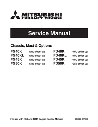
- 1. Service Manual 99739-16130For use with S6S and TB45 Engine Service Manual. Chassis, Mast & Options FG40K F29C-00011-up FG40KL F29C-50001-up FG45K F29C-80001-up FG50K F33B-50001-up FD40K F19C-00011-up FD40KL F19C-50001-up FD45K F19C-80001-up FD50K F28B-50001-up
- 2. FOREWORD This service manual is a guide for servicing Mitsubishi forklift trucks. For your convenience the instructions are grouped by systems as a ready reference. The long productive life of your forklift truck(s) depends on regular and proper servicing. Servicing consistent with what you will learn by reading this service manual. Read the respective sections of this manual carefully and familiarize yourself with all of the components before attempting to start a test, repair or rebuild job. The descriptions, illustrations and specifications contained in this manual are for trucks with serial numbers in effect at the time of printing. Mitsubishi Forklift Trucks reserves the right to change specifications or design without notice and without incurring obligation. The trucks listed in this manual are powered by TB45 gasoline engines or S6S diesel engines. For engine servicing, please refer to the applicable engine service manual. Pub. No. 99739-16130 Safety Related Signs The following safety related signs are used in this service manual to emphasize important and critical instructions: Indicates a specific potential hazard resulting in serious bodily injury or death. Indicates a specific potential hazard resulting in bodily injury, or damage to, or destruction of, the machine. Indicates a condition that can cause damage to, or shorten service life of, the machine. NOTE WARNING! CAUTION!
- 3. HOW TO READ THIS MANUAL Disassembly diagram (example) Sequence 1. Cover [Bolt, Washer] (part name) 2. Output shaft (part name) Suggestion for disassembly (1) Output shaft removal Symbols or abbreviations OP ...................Option R1/4.................Taper pipe thread (external) 1/4 inch (formerly PT1/4) Rc1/8...............Taper pipe thread (internal) 1/8 inch (formerly PT1/8) G1/4A..............Straight pipe thread (external) 1/4 inch (formerly PF1/4-A) Rp1/8...............Straight pipe thread (internal) 1/8 inch (formerly PS1/8) Unit: mm (in.) A 0.020 to 0.105 Clearance between (0.00079 to 0.00413) cylinder and piston 0.15 B (0.0059) A: Standard value B: Repair or service limit Disassembly sequence Each disassembly diagram is followed by Disassembly sequence and Suggestions for disassembly.
- 4. 4. Lower the forks or other implements to the ground before performing any work on the truck. If this cannot be done, make sure the forks or other implements are blocked correctly to prevent them from dropping unexpectedly. 5. Use steps and grab handles (if applicable) when mounting or dismounting a truck. Clean any mud or debris from steps, walkways or work platforms before using. Always face truck when using steps, ladders and walkways. When it is not possible to use the designed access system, provide ladders, scaffolds, or work platforms to perform safe repair operations. 6. To avoid back injury, use a hoist when lifting components which weigh 23 kg (50 lb.) or more. Make sure all chains, hooks, slings, etc., are in good condition and are of the correct capacity. Be sure hooks are positioned correctly. Lifting eyes are not to be side loaded during a lifting operation. 7. To avoid burns, be alert for hot parts on trucks which have just been stopped and hot fluids in lines, tubes and compartments. 8. Be careful when removing cover plates. Gradually back off the last two bolts or nuts located at opposite ends of the cover or device and pry cover loose to relieve any spring or other pressure, before removing the last two bolts or nuts completely. 9. Be careful when removing filler caps, breathers and plugs on the truck. Hold a rag over the cap or plug to prevent being sprayed or splashed by liquids under pressure. The danger is even greater if the truck has just been stopped because fluids can be hot. The serviceman or mechanic may be unfamiliar with many of the systems on this truck. This makes it important to use caution when performing service work. A knowledge of the system and/or components is important before the removal or disassembly of any component. Because of the size of some of the truck components, the serviceman or mechanic should check the weights noted in this Manual. Use proper lifting procedures when removing any components. Following is a list of basic precautions that should always be observed. 1. Read and understand all warning plates and decals on the truck before operating, lubricating or repairing the product. 2. Always wear protective glasses and protective shoes when working around trucks. In particular, wear protective glasses when pounding on any part of the truck or its attachments with a hammer or sledge. Use welders gloves, hood/goggles, apron and other protective clothing appropriate to the welding job being performed. Do not wear loose-fitting or torn clothing. Remove all rings from fingers when working on machinery. 3. Do not work on any truck that is supported only by lift jacks or a hoist. Always use blocks or jack stands to support the truck before performing any disassembly. SAFETY The proper and safe lubrication and maintenance for these forklift trucks, recommended by Mitsubishi, are outlined in the OPERATION & MAINTENANCE MANUAL for these trucks. Improper performance of lubrication or maintenance procedures is dangerous and could result in injury or death. Read and understand the OPERATION & MAINTENANCE MANUAL before performing any lubrication or maintenance on these trucks. Do not operate these trucks unless you have read and understood the instructions in the OPERATION & MAINTENANCE MANUAL. Improper truck operation is dangerous and could result in injury or death. WARNING! WARNING! WARNING!
- 5. 10. Always use tools that are in good condition and be sure you understand how to use them before performing any service work. 11. Reinstall all fasteners with same part number. Do not use a lesser quality fastener if replacements are necessary. Do not mix metric fasteners with standard nuts and bolts. 12. If possible, make all repairs with the truck parked on a level, hard surface. Block truck so it does not roll while working on or under truck. 13. Disconnect battery and discharge any capacitors (electric trucks) before starting to work on truck. Hang “Do not Operate” tag in the Operator’s Compartment. 14. Repairs, which require welding, should be performed only with the benefit of the appropriate reference information and by personnel adequately trained and knowledgeable in welding procedures. Determine type of metal being welded and select correct welding procedure and electrodes, rods or wire to provide a weld metal strength equivalent at least to that of parent metal. 15. Do not damage wiring during removal operations. Reinstall the wiring so it is not damaged nor will it be damaged in operation by contacting sharp corners, or by rubbing against some object or hot surface. Do not connect wiring to a line containing fluid. 16. Be sure all protective devices including guards and shields are properly installed and functioning correctly before starting a repair. If a guard or shield must be removed to perform the repair work, use extra caution. 17. Always support the mast and carriage to keep carriage or attachments raised when maintenance or repair work is performed, which requires the mast in the raised position. 18. Loose or damaged fuel, lubricant and hydraulic lines, tubes and hoses can cause fires. Do not bend or strike high pressure lines or install ones which have been bent or damaged. Inspect lines, tubes and hoses carefully. Do not check for leaks with your hands. Pin hole (very small) leaks can result in a high velocity oil stream that will be invisible close to the hose. This oil can penetrate the skin and cause personal injury. Use cardboard or paper to locate pin hole leaks. 19. Tighten connections to the correct torque. Make sure that all heat shields, clamps and guards are installed correctly to avoid excessive heat, vibration or rubbing against other parts during operation. Shields that protect against oil spray onto hot exhaust components in event of a line, tube or seal failure, must be installed correctly. 20. Relieve all pressure in air, oil or water systems before any lines, fittings or related items are disconnected or removed. Always make sure all raised components are blocked correctly and be alert for possible pressure when disconnecting any device from a system that utilizes pressure. 21. Do not operate a truck if any rotating part is damaged or contacts any other part during operation. Any high speed rotating component that has been damaged or altered should be checked for balance before reusing.
- 6. GROUP INDEX Items GROUP INDEX 1 2 3 4 5 6 7 8 9 10 11 12 13 14 15 GENERAL INFORMATION COOLING SYSTEM ELECTRICAL SYSTEM POWER TRAIN CLUTCHES Model View, Truck Models Covered, Serial Number Locations, Chassis and Mast Model Identification, Dimensions, Technical Data Structure, Removal and Installation, Inspection and Adjustment Structure and Functions, Major Electrical Components, Lamp Bulb Specifications, Battery Maintenance, Disassembly and Reassembly, Troubleshooting, Electrical Schematic Removal and Installation Dry Type Clutch, Wet Type Clutch, Pressure Plate Assembly, Clutch Booster, Clutch Master Cylinder, Clutch Release Cylinder, Adjustment, Troubleshooting, Service Data MANUAL TRANSMISSION POWERSHIFT TRANSMISSION FRONT AXLE AND REDUCTION DIFFERENTIAL REAR AXLE BRAKE SYSTEM STEERING SYSTEM Structure and Functions, Removal and Installation, Disassembly, Inspection and Repair, Reassembly, Troubleshooting, Service Data 1-Speed Transmission, Automatic 2-Speed Transmission, Troubleshooting, Service Data Structure and Function, Removal and Installation, Axle shafts and Hubs, Reduction Differential, Troubleshooting, Service Data (SIS) Structure, Removal and Installation, Rear Axle Assembly, Adjustment, Troubleshooting, Service Data, (FHS) Structure, Removal and Installation, Rear Axle Assembly, Steering Cylinder, Adjustment, Troubleshooting, Service Data Structures and Functions, Master Cylinder, Wheel Cylinders, Wheel Brakes, Adjustment and Test, Troubleshooting, Service Data HYDRAULIC SYSTEM MASTS AND FORKS (SIS) Structure and Function, Removal and Installation, Steering Gear, Power Cylinder, Troubleshooting, Service Data, (FHS) Structure and Functions, Removal and Installation, Steering Valve, Troubleshooting, Service Data Structure and Functions, Removal and Installation, Hydraulic Pumps, Control Valve, Lift Cylinders, Tilt Cylinders, Flow Regulator Valve, Down Safety Valve, Inspection and Adjustment, Testing, Hydraulic Circuit Diagram, Piping of Hydraulic System, Troubleshooting, Service Data Specifications, Structure, Removal and Installation, Disassembly and Reassembly, Inspection and Adjustment, Troubleshooting, Service Data SERVICE DATA OPTIONS Tightening Torque for Standard Bolts and Nuts, Maintenance Schedule, Parts to be Changed Periodically, Lubrication Instructions, Special Tools Radiator Screen Kit, Plate Fin Type Radiator Kit, Elevated Exhaust Kit, Headlamp Kit, Tail Lamp Upper Relocate Kit , Battery Switch Kit, Extinguisher Kit, Back Mirror Kit, Drawbar Pin, Low Head Guard Kit, Semi Under Side Guard Kit, Torque Converter Oil Filter Kit, Hydraulic Oil Cooler Kit, Gear Pump Seal Kit
- 7. Model View ................................................................................................ 1 – 1 Truck Models Covered ............................................................................ 1 – 1 Serial Number Locations ....................................................................... 1 – 2 Chassis and Mast Model Identification ............................................. 1 – 3 Dimensions ................................................................................................ 1 – 4 Technical Data .......................................................................................... 1 – 6 GENERAL INFORMATION 1
- 8. Model View Truck Models Covered This Service Manual provides servicing and maintenance information for the following trucks: 1-1 GENERAL INFORMATION 103190 Truck model Transmission Model code – Serial number Engine mounted FG40K Powershift F29C – 00011- up TB45 gasoline engine FG40KL Powershift F29C – 50001- up TB45 gasoline engine FG45K Powershift F29C – 80001- up TB45 gasoline engine FG50K Powershift F33B – 50001- up TB45 gasoline engine FD40K Manual F19C – 00011- up S6S diesel engine Powershift FD40KL Manual F19C – 50001- up S6S diesel engine Powershift FD45K Manual F19C – 80001- up S6S diesel engine Powershift FD50K Powershift F28B – 50001- up S6S diesel engine
- 9. Serial Number Locations 1-2 GENERAL INFORMATION Name plate (Gasoline- and LP-Gas- engine models) Chassis serial number (Diesel-engine models) (Gasoline- and LP-Gas-engine models) (Diesel-engine models)Transmission serial numberMast serial number Engine serial number 202761A
- 10. Chassis and Mast Model Identification 1-3 GENERAL INFORMATION [Chassis] FG 40 K Generation designator Maximum capacity/Load center 40: 4000 kg (8000 lb)/500 mm (20 in.) 40L: 4000 kg (8000 lb)/600 mm (24 in.) 45: 4500 kg (10000 lb)/600 mm (24 in.) 50: 5000 kg (11000 lb)/600 mm (24 in.) Maximum lifting height [“30” stands for 3000 mm (118 in.)] Order of the minor change (“A” for the original, “B” for the first change, “C” for the second change, and so on) Applicable truck model designation 40: 4 ton class 40L: 4 ton class 45: 4.5 ton class 50: 5 ton class Kind of mast V: simplex mast F: duplex mast M: triplex mast Major change (“2” for the original, “3” for the first change, and so on up to “9”) Engine type FG: gasoline engine type FD: diesel engine type [Mast] 4 V 40 A 30
- 11. Dimensions 1-4 GENERAL INFORMATION G K C L B H A J E I P M F OND 202762A
- 12. Thank you very much for your reading. Please Click Here Then Get More Information.