
Recommended
Recommended
More Related Content
Featured
Featured (20)
Sony Handycam Service Manual
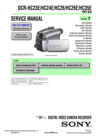
- 1. DCR-HC23E/HC24E/HC26/HC26E/HC35E RMT-830 SERVICE MANUAL LEVEL 3 US Model Ver 1.0 2006.01 Canadian Model Revision History AEP Model UK Model East European Model How to use North European Model Acrobat Reader E Model Argentine Model Australian Model Brazilian model Chinese Model Hong Kong Model N MECHANISM (MDX-N110) Korea Model Photo: DCR-HC35E Link MODEL INFORMATION TABLE PRINTED WIRING BOARDS REPAIR PARTS LIST SCHEMATIC DIAGRAMS The components identified by Les composants identifiés par une mark 0 or dotted line with marque 0 sont critiques pour la mark 0 are critical for safety. sécurité. Replace only with part num- Ne les remplacer que par une pièce ber specified. portant le numéro spécifié. DIGITAL VIDEO CAMERA RECORDER 2006A0500-1 DCR-HC23E/HC24E/HC26/HC26E/HC35E_L3 © 2006.1 9-876-927-11 Sony EMCS Co. Published by DI Technical Support Department
- 2. Model information table Model DCR-HC23E DCR-HC24E DCR-HC26 DCR-HC26E DCR-HC35E US, CND, E, AR NE, E, AUS, CH, Destination AEP, EE, NE AEP, UK, EE, NE BR, KR HK AEP, UK, EE, NE Color system PAL PAL NTSC PAL PAL DV Interface OUT OUT IN/OUT IN/OUT IN/OUT (Note) Remote commander × a × × a Cradle (Handycam Station) × × × × a CR board × × × × CR-061 Note: DV Interface on the Cradle (Handycam Station) • Abbreviation AR : Argentine model AUS : Australian model BR : Brazilian model CH : Chinese model CND : Canadian model EE : East European model HK : Hong Kong model J : Japanese model JE : Tourist model KR : Korea model NE : North European model DCR-HC23E/HC24E/HC26/HC26E/HC35E_L3 —2—
- 3. CAUTION Danger of explosion if battery is incorrectly replaced. Replace only with the same or equivalent type. SAFETY-RELATED COMPONENT WARNING!! ATTENTION AU COMPOSANT AYANT RAPPORT À LA SÉCURITÉ! COMPONENTS IDENTIFIED BY MARK 0 OR DOTTED LINE WITH LES COMPOSANTS IDENTIFÉS PAR UNE MARQUE 0 SUR LES MARK 0 ON THE SCHEMATIC DIAGRAMS AND IN THE PARTS DIAGRAMMES SCHÉMATIQUES ET LA LISTE DES PIÈCES SONT LIST ARE CRITICAL TO SAFE OPERATION. REPLACE THESE CRITIQUES POUR LA SÉCURITÉ DE FONCTIONNEMENT. NE COMPONENTS WITH SONY PARTS WHOSE PART NUMBERS REMPLACER CES COMPOSANTS QUE PAR DES PIÈSES SONY APPEAR AS SHOWN IN THIS MANUAL OR IN SUPPLEMENTS DONT LES NUMÉROS SONT DONNÉS DANS CE MANUEL OU PUBLISHED BY SONY. DANS LES SUPPÉMENTS PUBLIÉS PAR SONY. SAFETY CHECK-OUT After correcting the original service problem, perform the following safety checks before releasing the set to the customer. 1. Check the area of your repair for unsoldered or poorly-soldered Unleaded solder connections. Check the entire board surface for solder splashes Boards requiring use of unleaded solder are printed with the lead- and bridges. free mark (LF) indicating the solder contains no lead. 2. Check the interboard wiring to ensure that no wires are (Caution: Some printed circuit boards may not come printed with the lead free mark due to their particular size.) "pinched" or contact high-wattage resistors. 3. Look for unauthorized replacement parts, particularly : LEAD FREE MARK transistors, that were installed during a previous repair. Point Unleaded solder has the following characteristics. them out to the customer and recommend their replacement. • Unleaded solder melts at a temperature about 40°C higher than 4. Look for parts which, through functioning, show obvious signs ordinary solder. of deterioration. Point them out to the customer and Ordinary soldering irons can be used but the iron tip has to be recommend their replacement. applied to the solder joint for a slightly longer time. 5. Check the B+ voltage to see it is at the values specified. Soldering irons using a temperature regulator should be set to 6. Flexible Circuit Board Repairing about 350°C. • Keep the temperature of the soldering iron around 270˚C Caution: The printed pattern (copper foil) may peel away if the during repairing. heated tip is applied for too long, so be careful! • Do not touch the soldering iron on the same conductor of the • Strong viscosity Unleaded solder is more viscous (sticky, less prone to flow) than circuit board (within 3 times). ordinary solder so use caution not to let solder bridges occur such • Be careful not to apply force on the conductor when soldering as on IC pins, etc. or unsoldering. • Usable with ordinary solder It is best to use only unleaded solder but unleaded solder may also be added to ordinary solder. DCR-HC23E/HC24E/HC26/HC26E/HC35E_L3 —3—
- 4. TABLE OF CONTENTS Section Title Page 4. PRINTED WIRING BOARDS AND SCHEMATIC DIAGRAMS 4-2. Schematic Diagrams ························································ 4-3 4-3. Printed Wiring Boards ··················································· 4-25 4-5. Mounted Parts Location ················································ 4-35 5. REPAIR PARTS LIST 5-2. Electrical Parts List ······················································· 5-14 DCR-HC23E/HC24E/HC26/HC26E/HC35E_L3 —4—
- 5. 4-2. SCHEMATIC DIAGRAMS Link VC-416 BOARD (1/12) VC-416 BOARD (7/12) (A/D CONVERTER, TIMING GENERATOR) (CAMERA/MECHA CONTROL) VC-416 BOARD (2/12) (LENS DRIVE, EVR) VC-416 BOARD (8/12) (SERVO) VC-416 BOARD (3/12) VC-416 BOARD (9/12) (HI CONTROL) (DV SIGNAL PROCESS, DV INTERFACE) VC-416 BOARD (4/12) (REC/PB AMP) VC-416 BOARD (10/12) (DC IN) VC-416 BOARD (5/12) VC-416 BOARD (11/12) (VIDEO OUT, AUDIO I/O) (DC/DC CONVERTER) VC-416 BOARD (6/12) (LCD/EVF DRIVE) VC-416 BOARD (12/12) (CONNECTOR) COMMON NOTE FOR SCHEMATIC DIAGRAMS DCR-HC23E/HC24E/HC26/HC26E/HC35E_L3
- 6. 4-2. SCHEMATIC DIAGRAMS 4. PRINTED WIRING BOARDS AND SCHEMATIC DIAGRAMS 4-2. SCHEMATIC DIAGRAMS THIS NOTE IS COMMON FOR SCHEMATIC DIAGRAMS (In addition to this, the necessary note is printed in each block) (For schematic diagrams) 1. Connection • All capacitors are in µF unless otherwise noted. pF : µ Pattern box µF. 50 V or less are not indicated except for electrolytics Color bar chart and tantalums. Pattern box PTB-450 For PTB-450: J-6082-200-A J-6020-250-A • Chip resistors are 1/10 W unless otherwise noted. or kΩ=1000 Ω, MΩ=1000 kΩ. Small pattern box For PTB-1450: • Caution when replacing chip parts. PTB-1450 J-6082-559-A New parts must be attached after removal of chip. J-6082-557-A Be careful not to heat the minus side of tantalum capacitor, Because it is damaged by the heat. L = 1 m (PTB-450) • Some chip part will be indicated as follows. L = 40 cm (PTB-1450) Example C541 L452 22U 10UH Pattern box Front of the lens TA A 2520 L Camera Kinds of capacitor External dimensions (mm) Case size • Constants of resistors, capacitors, ICs and etc with XX indicate that they are not used. In such cases, the unused circuits may be indicated. 2. Adjust the distance so that the output waveform of • Parts with ★ differ according to the model/destination. Fig. a and the Fig. b can be obtain. Refer to the mount table for each function. H • All variable and adjustable resistors have characteristic Yellow Magenta White curve B, unless otherwise noted. Cyan Green • Signal name Red Blue XEDIT → EDIT PB/XREC → PB/REC • 2: non flammable resistor • 5: fusible resistor • C: panel designation • A: B+ Line • B: B– Line A B A=B B A • J : IN/OUT direction of (+,–) B LINE. Fig. a (Video output terminal output waveform) • C: adjustment for repair. • A: not use circuit Electronic beam (Measuring conditions voltage and waveform) scanning frame • Voltages and waveforms are measured between the measurement points and ground when camera shoots CRT picture frame color bar chart of pattern box. They are reference values and reference waveforms. (VOM of DC 10 MΩ input impedance is used) • Voltage values change depending upon input impedance of VOM used.) Fig.b (Picture on monitor TV) Precautions for Replacement of Imager When indicating parts by reference number, please • If the imager has been replaced, carry out all the adjustments include the board name. for the camera section. • As the imager may be damaged by static electricity from The components identified by mark 0 or dotted line with its structure, handle it carefully like for the MOS IC. mark 0 are critical for safety. In addition, ensure that the receiver is not covered with Replace only with part number specified. dusts nor exposed to strong light. Les composants identifiés par une marque 0 sont critiques pour la sécurité. Ne les remplacer que par une pièce portant le numéro spécifie. DCR-HC23E/HC24E/HC26/HC26E/HC35E_L3 4-3
- 7. 1 2 3 4 5 6 7 8 9 10 11 12 13 14 CAM_15V VC-416 BOARD (1/12) CAM_-7.5V A_2.8V (11/12) A A/D CONVERTER, TIMING GENERATOR D_2.8V REG_GND XX MARK:NO MOUNT NO MARK:REC/PB MODE C3011 XX R:REC MODE P:PB MODE C3029 R3012 X3001 D3001 CL3001 XX XX 36MHz 1SV329(TPL3) FREQ_AMPOUT @001 FB3003 R3004 C3014 R3007 C3009 0.01u XX 0.01u 470k (2/12) B C3006 R3016 4.7u XX R2.2/P0 R2.7/P0 1.6 1.1 2.8 1.2 1.5 1.2 12 11 10 9 8 7 6 5 4 3 2 1 VICK(CL) SYSCK VDD1 CHCK TEST CK VSS2 OSCO OSCI VSS1 PBLK CLPDM CN3001 14P C CCD_OUT GND 14 13 V4 C3028 2.7 R1.3/P0 V4 12 XX 13 VDD2 ID 48 V3 V3 11 14 VSS3 CKCONT1 47 V2 XSHP R1.7/P0 2.7 V2 10 15 XSHP CKCONT2 46 V1 XSHD R1.7/P0 R2.7/P0 CD-631 V1 9 16 XSHD AVD 45 CN101 C3001 C3027 2.9 GND 8 0.01u XX R0.4 17 XRS AHD 44 THROUGH THE /P0 2.8 FLEXIBLE FLAT CABLE H2 7 2.7 18 RG IC3001 VDD5 43 R2.8/P0 @002 (7/12) D (FFC-063) PAGE 4-5 H1 6 2.7 19 VDD3 TIMING GENERATOR DSGAT 42 0 CAM_DD_ON (11/12) RG 5 R3013 C3003 20 VDD4 XV1 41 of LEVEL2 XX IC3001 VSHT 68p R1.6/P0 CXD2444AR-T4 2.8 XRST_VTR CAM_SCK (2/12) H1 VSHT VH 4 3 R1.4/P0 21 22 H2 RST SEN 40 39 R0.2/P2.7 XCS_TG CAM_SO CAM_SCK CAM_SO @003 (3/12) (7/12) C3004 0 CAM_SO VL 2 R3014 68p 23 VSS4 SSI 38 CAM_SI GND 1 XX 24 NC SSK 37 2.6 CAM_SCK CAM_SI @004 (3/12) (7/12) XCS_TG XCS_TG CH_SO CH_SCK CH_SO @005 E CH_SCK XSHT XSG1 VGAT SSO CS_CH (7/12) V2 V1 VM VH NC V3 VL V4 CS_CH (3/12) 25 26 27 28 29 30 31 32 33 34 35 36 XRST_VTR XRST_VTR @006 (7/12) R14.7/P0 R-0.3/P0 (8/12) R-7/P0 R-7.4/P0.3 R-7/P0 R-7.4/P0.3 R2.7/P0 2.5 0 C3005 1u R-0.3/P0 TG_ID C3013 0.1u TG_VGAT CAM_SI R3001 100k TG_ZV1 F C3002 TG_ZSG1 VSHT 0.33u V1 V3 V4 V2 VCK TG_AVD TG_AHD FE_CLPOB @007 G (3/12) AD9 AD9 AD8 AD7 AD6 AD5 AD4 AD3 AD2 AD1 AD0 AD9 L3001 AD8 10uH AD8 0 0 AD7 AD7 12 11 10 9 8 7 6 5 4 3 2 1 C3024 AD6 10u AD6 R0.8/P0 R1.1/P0 R1/P0 R1/P0 R1/P0 R1.1/P0 R1.1/P0 R1.1/P0 AD5 DVSS D9 D8 D7 D6 D5 D4 D3 D2 D1 D0 DVSS FB3004 AD5 AD4 AD4 AD3 H AD2 AD3 2.8 2.8 CH_SCK AD2 C3007 13 DRVDD XSCK 48 AD1 1u 0 CH_SO AD1 14 DRVSS SI 47 AD0 2.7 CS_CH AD0 15 DVSS XCE 46 1.6 C3026 0.1u 16 ADCLK SYSV 45 2.8 17 DVDD LATCHSELECT 44 2.8 18 DVDD IC3002 RSTB 43 2.8 XRST_VTR R3015 XX R2.2/P0 S/H. AGC, A/D I 2.7 19 PBLK 20 CLPOB CONVERTER IC3002 AVSS AVSS 42 41 XSHP R1.7/P0 VSP995PTR 2.8 21 XSHP AVDD 40 XSHD R1.7/P0 1.3 C3021 22 XSHD REFN 39 0.1u R2.7/P0 1.8 C3022 23 CLPDM REFP 38 0.1u 2.8 1.5 C3023 24 AVDD CMLEVEL 37 0.1u CCD_GND CHROMA R1.5/P0 CCD_IN AVDD AVDD AVSS AVSS AVSS J LINE L1+ L2+ L 25 26 27 28 29 30 31 32 33 34 35 36 2.8 R1/P0 R0.9/P0 2.8 C3030 R3017 XX XX C3008 XX C3016 C3019 0.33u 0.1u C3020 1u K C3012 R3005 FB3005 0.1u 47 05 DCR-HC23E/HC24E/HC26/HC26E/HC35E_L3 4-6 VC-416 (1/12)