SlideShare a Scribd company logo
1 of 115
Download to read offline
CSL BIENNIAL REPORT 2010 - 2011


                                          © TILT ULG DR


                    Centre Spatial de Liège
                       Université de Liège
                              Liège Science Park
                                 Avenue Pré Aily
                      B-4031 ANGLEUR – Belgium
                               +(0)32 4 382.46.00
                               www.csl.ulg.ac.be
2   CSL Biennal Report 2010-2011
TABLE OF CONTENT
TABLE OF CONTENT ........................................................................................................................................................... 3
FOREWORD ....................................................................................................................................................................... 5
CSL IN A FEW FIGURES ....................................................................................................................................................... 8
LABORATORIES ................................................................................................................................................................ 10
    1.    TESTS FACILITIES LABORATORY ( RESP. I.TYCHON ) ...................................................................................... 10
       Works performed during the period 2010-2011........................................................................................................ 14
       Focal 1.5 chamber ................................................................................................................................................... 14
       Focal 2 chamber ...................................................................................................................................................... 15
       Focal 3 chamber ...................................................................................................................................................... 16
       Focal 5 chamber ...................................................................................................................................................... 20
       Focal 6.5 chamber ................................................................................................................................................... 24
       Vibration Facilities ................................................................................................................................................... 26
       Maintenance and Facility Upgrade .......................................................................................................................... 33
       External activities .................................................................................................................................................... 33
    2.    OPTICAL DESIGN & METROLOGY LABORATORY ( RESP. Y. STOCKMAN ) ........................................................ 36
       The competences..................................................................................................................................................... 36
       Major events in 2010 and 2011................................................................................................................................ 38
    SEE DESCRIPTION PAGES 13 AND 14. ..................................................................................................................................... 45
       Optical Design Workshop ........................................................................................................................................ 45
    3.    LASERS & NDT LABORATORY ( RESP. M. GEORGES ) ................................................................................... 47
       The team................................................................................................................................................................. 47
       The competences..................................................................................................................................................... 47
       Major equipment .................................................................................................................................................... 48
    4.    SIGNAL PROCESSING LABORATORY ( RESP. C. BARBIER )............................................................................. 53
       OpticaSAR (Synthetic Aperture Radar) image processing. ......................................................................................... 53
       Optical and spectral data processing ....................................................................................................................... 53
       Training................................................................................................................................................................... 53
    5.    THERMAL & MECHANICAL DESIGN LABORATORY ( RESP. P. JAMOTTON)....................................................... 58
       GSE facilities advanced thermal test environment designed upon requirement. ........................................................ 58
       Extended capabilities for space condition simulation (from 5K to 400 K). .................................................................. 58
       Cryogenic expertise. ................................................................................................................................................ 58
       Solar systems to increase energy concentration and spacecraft/payload thermal efficiency and autonomy ............. 58
       Space payload mechanism Design ........................................................................................................................... 58
    6.    SURFACE ENGINEERING LABORATORY ( RESP. K. FLEURY ) ........................................................................... 61
       Surface coating for space applications ..................................................................................................................... 61
       Surface micro texturing ........................................................................................................................................... 61
       Laser ablation process ............................................................................................................................................. 61
       Ion Beam Polishing .................................................................................................................................................. 61
    7.    ELECTRONICS LABORATORY ( RESP. N. MARTIN ) .......................................................................................... 64
    8.    QUALITY ASSURANCE LABORATORY ( RESP. V. DESCAMPS ) .......................................................................... 68
       Detection of organic contamination by infrared spectroscopy .................................................................................. 68
       Monitoring of particle contamination ...................................................................................................................... 69
PROGRAMMES ................................................................................................................................................................ 71
    1.    TEST PROGRAMMES ( RESP. C. GRODENT ) .................................................................................................. 71
    2.    SPACE SYSTEM PROGRAMMES (RESP. E. RENOTTE )...................................................................................... 77
    3.    TECHNOLOGY PROGRAMMES ( RESP. JH LECAT ) ........................................................................................... 85
       Interreg Projects ..................................................................................................................................................... 88
    4.    QUALITY MANAGEMENT ( RESP. M. THOMÉ).................................................................................................... 91
       European Space Agency........................................................................................................................................... 91
       ISO certification ....................................................................................................................................................... 91
AWARDS .......................................................................................................................................................................... 92
ACADEMIC ACTIVITIES ..................................................................................................................................................... 93
    LECTURES GIVEN BY CSL SCIENTISTS AND PROFESSORS AT ULG ..................................................................................................... 93
    LECTURES FOR EXTERNAL CUSTOMERS .................................................................................................................................... 95
    SEMINARS / CONFERENCES ORGANIZED BY CSL ........................................................................................................................ 96
    MASTER THESES............................................................................................................................................................... 97
    PHD THESES ................................................................................................................................................................... 97
    ON GOING PHD THESES ..................................................................................................................................................... 98
    TRAINEE PROGRAMS ......................................................................................................................................................... 99
    PUBLICATIONS ............................................................................................................................................................... 101
INTERNATIONAL RELATIONSHIP .................................................................................................................................... 108
PUBLIC OUTREACH......................................................................................................................................................... 109
    VISITS .......................................................................................................................................................................... 109
    SCHOOLS ...................................................................................................................................................................... 109
    ASSOCIATIONS ............................................................................................................................................................... 109
    EXHIBITIONS .................................................................................................................................................................. 110
PARTICIPATION TO EXTERNAL COMMITTEES ................................................................................................................. 111
BOARDS ......................................................................................................................................................................... 112
RUNNING PROJECTS ...................................................................................................................................................... 113
COMMENTS ................................................................................................................................................................... 115


            4                                                                 CSL Biennal Report 2010-2011
FOREWORD


                                       T. Chantraine
                                       General Manager


For CSL, the two former years were definitely transitional.
On the external side, CSL faces a profound mutation of its environment. Space exploration is not
any more a reserved area for the lone scientists. Access to space became a strategic goal for the
emerging nations and a commercial playground for big aerospace companies. Orders providers
have changed and the role of the space agencies considerably evolved.
Remember. In the 90‟s, the European Space Agency was directly coordinating the design and the
integration of satellites and payloads. Today, those works are globally contracted to the industry.
In the same kind of logic, this is an industrial joint-venture which operates the historical ESTEC
Test Centre since 2000. The participating companies are both CSL competitors.
Like it or not, space is now a market, still surrounded by several guides of geographical
redistribution, but more and more led by profit, competition and risk reduction. CSL has to
consider this situation very seriously, and it will.

Internally, this biennial was quite turbulent too. During this period, CSL proceeded to a strong
reengineering under the University supervision authority. The management processes and the
global strategy were scrutinized through this work, which end up with the definition of a brand
new organization headed by a straight vision:

        •           CSL is a high level Research Center of the University of Liege devoted to
                           applied research and managed as a “profit center”.

            •        CSL performs Research Technology Development & Innovation (RTDI)
                                  activities mainly related to space.

                •       CSL commits to be a significant actor of the regional economical
                                             development.

        •           CSL nourishes a state of the art research related to space sciences within
                                         the University of Liege.


                                    CSL Biennal Report 2010-2011                                 5
This statement clearly beacons CSL missions on a route linking deep science to space system
development and technology swarming (through applications, expertise and high level training for
instance).
The inner matrix organization designed to support this activity also aims to yield a dual objective:

   1. to provide a better visibility of the technological excellence areas of CSL and to clarify
      responsibilities as well as points of contact throughout the organization.

   2. to reinforce and to improve our marketing activity.


                                                                                 T. Chantraine              I. Laven
                                                                                General Manager             Assistant


       P. Rochus                                                                                                                                    C. Bertrand (DGM)
   Academic & Scientific                                                                                                                               Finance, HR,
         Affairs                                                                                                                                       Administration

                                              A. Cucchiaro
                                         Official Representative


                                             S. Habraken                                                                                                                Ch. Bertrand
                                            Scientific Advisor                                                                                                              H.R.


        J. Bernier
      Contract Office                                                                                                                  M. Thomé                         F. Duchateau
        Industrial                                                                                                                      PA/QA                            Accounting
       Cooperation


                             Signal      Electronics          Surface      Lasers &      Optical Design   Mechanical        Test         Quality
                           Processing    N. Martin          Engineering      NDT          & Metrology      & Thermal     Facilities        Lab
                                                                                                                                                                         A. Castias
                           Ch. Barbier                       K. Fleury    M. Georges     Y. Stockman      Engineering   I. Tychon     V. Descamps
                                                                                                                                                                        Administration
                                                                                                          P. Jamotton


     Test
     Programmes
     Ch. Grodent                                                                                                                                                      Ch. Bertrand
                                                                                                                                                                    Facility & Logistics


     Space System
     Programmes                                                                                                                                                          Fr. Collard
     E. Renotte                                                                                                                                                              I.T.


     Technology
     Programmes
     J-H. Lecat


Note that this organization includes a specific academic and scientific director. This marks our
strong anchorage to the Liege University and shows our willingness to keep a high level of
scientific excellence using the enormous competence reservoir of the institution.

You will find many traces of this excellence all along those pages as CSL carried out complex and
innovative projects within the 2010-2011 period. Those works allowed CSL to maintain an
international reputation and to join prestigious consortium preparing the future of the space
exploration. From that prospective, the announcement in October 2011 of the Solar Orbiter
selection for the M1 slot of the ESA Cosmic Vision program was a major event for us.


         6                                                                CSL Biennal Report 2010-2011
Solar Orbiter is an extremely challenging mission crafted to stare closely at the sun. In this
project, CSL owns the PIship of the Extreme Ultra-Violet Imager (EUI) and participates to the
design and integration of the HI instrument. With this program, CSL consolidates a leading
position in scientific system development and secures a substantial workload for the five coming
years.
This success combined to the dynamic we expect from the new organization allows us to get a real
ambition of growth. This report will show you that this ambition stands on robust foundations.


Thierry Chantraine


                               CSL Biennal Report 2010-2011                             7
CSL in a FEW FIGURES


   8                   CSL Biennal Report 2010-2011
CSL Biennal Report 2010-2011   9
LABORATORIES


           1. Tests Facilities Laboratory ( Resp. I.Tychon )


       6 vacuum chambers from 0.25m to 6.5m diameter, capable of extended vacuum
       and thermal cycling, equipped with optical bench laying on seismic device
       (vibration decoupling ).

       Vibration shakers ( 5 – 3000Hz , 80 -200KN )
       Possibility of cryovibrations.


The team

The team consists in 7 persons who are presented in the following organization chart.


                                                      Isabelle TYCHON


                                    Scientific team                 Technical team


                           Isabelle DOMKEN                               Martin BROEN
                           Sylvie LIEBECQ                                Josiane VERSTRAELEN
                                                                         Ghislain VAN aUBEL
                                                                         Robert SCHETTER


     10                                         CSL Biennal Report 2010-2011
The CSL performs various qualifications on space instruments or equipments by submitting them to
environmental space conditions.

The two main types of test campaigns are :

   -   thermal vacuum qualification,
   -   vibration qualification.

A specific facility has also been developed at CSL to allow a mixed full validation : vibration under
vacuum at cryogenic temperature. This facility is called „Cryovibration Test Facility‟.
Generally, when thermal vacuum conditions (hot or cold cases) are imposed on an optical
instrument, optical stimuli are simultaneously injected in order to validate the global optical
performance in space conditions.
Some specific instruments require a cryogenic environment (4.2K – 20K). This can be achieved
with cryogenic techniques involving liquid Helium.
The key specific CSL competencies in the test laboratory are : thermal and vibration control,
cryogeny and optics.


Thermal Vacuum campaigns

CSL performs various qualification thermal vacuum test campaigns using its own thermal vacuum
chambers with associated thermal systems.
Gaseous nitrogen (GN2) is generally used to feed thermal panels with an automatically adjusted
temperature in the [-150°C, +100°C] range. For specific colder temperatures, liquid nitrogen
(LN2) is also used.

Three types of campaigns are generally proposed:

       Bake-out and outgassing tests: a controllable warm up is imposed in a specimen during a
       specified period under vacuum to evaporate contaminants and to obtain a perfectly clean
       instrument. Any contamination risk must be indeed eliminated to avoid any optical
       performance degradation.
       Thermal cycles : this kind of test simulates the “in-orbit” extreme conditions with a
       succession of cold and hot temperatures. The instrument under test should survive to non-
       operating temperatures while performance should comply within the operating temperature
       range.
       Thermal balance tests : Specific radiative / conductive thermal conditions are imposed on
       the test specimen to simulate a stable environment as it will be seen in orbit during the
       operational phases. Artificial thermal gradients can be introduced in the instrument and the
       subsequent performance degradation is measured. Additionally the measured temperature
       cartography is compared with the corresponding thermal predictions.

All the parameters (pressure, temperature, LN2 level) are monitored and recorded during the test
campaigns. All these key data can also be analyzed in real time via a dedicated secure web
connection.
The CSL chambers are all equipped with a perfectly stable optical bench, fully decoupled from
external parasitic vibration perturbations. All benches are connected to massive seismic blocks.
Microvibration levels can be measured in real-time with specific seismic accelerometers.
For specific test campaigns of space instruments working in the millimeter or sub-millimeter
wavelength range, a cryogenic environment is mandatory to reduce the own radiation of the
tested instrument itself.
Two Helium liquefiers / refrigerators can dispatch the cold fluid to obtain environmental
temperatures below 20K (4.2K for liquid Helium bath).

                                CSL Biennal Report 2010-2011                                11
Finally, a global test campaign must always be conducted in a perfectly clean environment from
the preparation phase to the final packing. This is managed by the cleanliness control section. The
assembly and integration are realized in one of the two CSL clean rooms (ISO 7 as a baseline and
ISO 5 cleanliness upon request).
The level of cleanliness is permanently controlled via dedicated equipments like particle
contamination samples (PFO), molecular contamination samples (FTIR), Airborne Particle Counter,
etc….Under vacuum, the level of contaminants is monitored in real time via RGA (Residual Gas
Analyzer) or TQCM (Temperature Quartz Controlled Microbalance) while a LN2 cold panel (cold
trap) is permanently activated.


CSL vacuum chambers and cryovibration facility


                    Focal 1.5                                               Focal 2


                     Focal 3                                                Focal 5


                    Focal 6.5                            Cryovibration chamber connected to the shaker


     12                                   CSL Biennal Report 2010-2011
CSL Helium Liquefiers / Refrigerators


       KOCH 1630 Helium Liquefier/Refrigerator                    LINDE TCF20 Helium Liquefier/Refrigerator


                                   CSL Biennal Report 2010-2011                                           13
Works performed during the period 2010-2011

Focal 1.5 chamber

Several small thermal tests have been performed in the chamber Focal 1.5 in 2010-2011 among
which :


Solar Orbiter Sun Sensor ( ESA )

The goal of the project is to select, adapt and qualify the sun sensor for the Solar Orbiter
platform. CSL will demonstrate that it will be operational under the extreme environmental
conditions due to the close proximity of the satellite with the Sun (0,25 AU).
The extreme solar flux encountered during the
mission     lifetime   required    to    develop
sophisticated thermal protections for the
complete satellite, such as front heat shield,
thermal baffles and cooling radiators. The sun
sensor is a crucial element for ensuring the
pointing of the platform which is essential for
the overall thermal control of the mission. This
project is run for ESA with the Lambda-X
company as prime. CSL is involved in the
thermal aspect and the qualification of the
system.


                                                                    TNO-TPD sensor

The modified Sun Sensor from TNO has been tested in Focal 1.5 under 13 solar constants.


Solar Orbiter EUI
( started in 2006)


See a more detailed presentation on page 39

The aim of the tests in Focal 1.5 performed in 2011 concerned the thermo optical characterization
of the entrance filters.


List of Vacuum tests in Focal 1.5 – 2010/2011

CLS Blank tests                                 VINCI Valve
       June to September 2010                         September 2011
       Customer : ESA                                 Customer : Techspace Aero

Sunsensor                                       Solar Orbiter filters
      October to November 2010                         November to December 2011
      Customer : CSL (end customer: ESA)               Customer : CSL (end customer: ESA)


     14                                  CSL Biennal Report 2010-2011
Focal 2 chamber

The main activities in the 2010-2011 period of time are related to the optical validation of the
TanDEM X_TLA.


TanDEM-X_TLA

A blank test campaign for the Tandem-X telescope has been performed in March 2010. The
purpose was to measure its optical performance via interferometric method at various operating
temperature.

The Telescope Assembly (TLA) is a small telescope used as the optical antenna of an optical
terminal. It can be used for transmission and for reception.
It has been asked to CSL to perform the thermal cycling test of the TLA (QM and FM model) and
to measure its optical performances under vacuum for different thermal cases.


.
                                                              Set up integration in the chamber
                TLA overview


List of Vacuum tests in Focal 2 – 2010/2011

TANDEM-X Blank test
     March 10
     Customer: RUAG Switzerland

TANDEM-X _TLA QM
     October 10
     Customer: RUAG Switzerland

TANDEM-X _TLA_FM
     November 10
     Customer: RUAG Switzerland


                               CSL Biennal Report 2010-2011                                   15
Focal 3 chamber

2010

ALADIN-Bakeout tests on permacell, MLI, STRO, tedlar for EADS Astrium SAS
February – June 2010

Aladin is an instrument containing a UV high fluence laser
The laser beam when crossing outgassing product can produce Laser Induced Contamination (LIC)
on the optics, especially in vacuum.
The materials identified from the beginning (from literature) as being the most dangerous for the
LIC problem are the silicone and the aromatics. A test campaign on materials behavior with
respect to LIC has been conducted by ESA to identify those not to be used. It has shown that a
large number of materials cause LIC at 355nm
The telescope is the last part of Aladin where the emitting path of the UV laser is crossing optical
parts under vacuum.
Some individual parts have already been baked (MLI, structure) but not all of them and the
telescope integration has added some other material which outgassed. It is why in order to reduce
as far as possible, the amount of outgassing material in the vicinity of the M2 and the TRO
window, it has been agreed to perform a bake out at telescope level.


            Metalic parts bakeout                              Permacel bakeout


              Kapton bakeout                                     Tedlar bakeout


     16                                   CSL Biennal Report 2010-2011
OLCI-Wheel bakeout tests & cycling on calibration wheel FM For Thales
September 2010 – November 2010


Within the Sentinel 3 components, there is a multi-spectral optical imager for Ocean and Land
Colour operational applications (with equivalent ENVISAT MERIS baseline performance), named
OLCI (Ocean and Land Colour Imager).
The OLCI instrument embarks a Calibration Assembly, made of a positioning mechanism and the
appropriate reference diffusers which is the purpose of the current project. The overall OLCI is
composed of the structure equipped with the units necessary for all functions and with the thermal
hardware. All optical elements are supported on a stable flat panel (optical bench). Other
equipments are distributed on the other panels. Five identical cameras point to the Earth,
Eastwards and Westwards from the sub-satellite point. The Calibration Mechanism is mounted on
the Instrument Earth side.
In this project, CSL is responsible for the design, manufacturing, verification, calibration and
delivery of the Calibration Assembly that is composed of the Calibration Mechanism and the
Calibration Hardware. This work is performed in collaboration with CSEM that acts as a sub-
contractor of CSL.
The work of CSL is divided in two units: the calibration mechanism and the calibration hardware.


            OLCI wheel bakeout                        OLCI calibration wheel cycling test

2011

                               CSL Biennal Report 2010-2011                                 17
AIS Gapfiller Vesselsat-1 for Luxspace
August 2011


AIS, or the “Automatic Identification System” is a technology embarked on all vessels above 299
GRT, which is used as anti-collision system. Many coastal countries have established shore based
receiving stations to monitor the vessel traffic. However, the reach of these stations is limited to
more or less 100 nautical miles.
Satellite AIS is a new emerging technology that provides a cost effective solution for monitoring
vessel traffic and the individual positions of ships around the world. Such vessel monitoring
information is of particular interest to ship owners and port authorities but raises also
expectations to be useful for supporting maritime policy and the creation of maritime awareness
information.

Satellite AIS is considered as an add-on to the coastal stations that extends the vessel monitoring
capability for safety and security aspects to a global scale for both the institutional and private
sector.
The microsatellite has been cycled between 0 and +60 °C in August 2011


  AIS Gapfiller Vesselsat in the cycling test
                 configuration


     18                                    CSL Biennal Report 2010-2011
Codechamps : bakeout of three encoders
October 2011

Bake-out of 3 encoders at +85 °C

MSI Diffuser ( Multi Spectral Instrument ) for CSL ( end customer EADS ASTRIUM SAS )
October 2011

In the framework of the Global Monitoring for Environment and Security program (GMES), ESA
develops Sentinel-2, a multispectral optical imaging system for Earth Remote Sensing with
terrestrial applications providing continuity and enhancement to Landsat and SPOT type missions.

The diffuser is a sun-light diffuser used for absolute radiometric calibration of all spectral
channels. The calibration is typically performed once a month when flying over the North Pole.
During calibration phase, a mechanism deploys the diffuser in front of the instrument.
The sun diffuser covers the full field of view.

All the diffusers have been baked till 80 °C during 72 hours in a dedicated set up


     MSI diffusers integration for bakeout
                                                                   View of diffusers


List of Vacuum tests in Focal 3 – 2010/2011

Baking Aladin permacell, MLI, tedlar, STRO        CODECHAMP – Bakeout 3 encoders
       February – July 10                              September-October 11
       Customer: CSL (end customer:                    Customer: Codechamp
       Astrium)

OLCI – wheel bakeout                              GAIA RVS – blank test for cycling test
      September 10                                      October 11
      Customer: CSL (end customer: TAS-F)               Customer : Astrium SAS( France)

OLCI calibration mechanism cycling                MSI diffusers – Blank test & bakeout tests
      November 10                                        October 11
      Customer: CSL (end customer: TAS-F)                Customer : CSL (end customer:
                                                         Astrium)

Luxspace – AIS Gaspfiller -cycling
      Augustus 11
      Customer : Luxspace

                                CSL Biennal Report 2010-2011                                   19
Focal 5 chamber

2010

ALADIN For EADS Astrium SAS
February - June 2010

In 2010, the activities in Focal 5 were principally based on the ALADIN project.
Four tests have occurred for the ALADIN: a blank test of the thermal tent, a blank test for the LIC
test, a bakeout of the Aladin telescope and the LIC test, between January and July 2010.

The ALADIN Telescope has been installed inside the Focal 5 chamber and, once the vacuum is
obtained, the high powered laser is activated by EADS and LIC measurements are performed on
optical samples.
Various trials have been done to finally obtain an acceptable and compliant test set-up


   Integration of the Telescope on Focal 5                        Preparation Phase
          bench (ISO5 cleanliness)

     All the bake-out tests were permanently
               controlled with TQCM
All the suspected contaminants like metallic staples, Kapton scotch and glue, Aluminium parts,
Kapton foils, Mechanical items not perfectly cleaned have been previously baked in the Focal 3
chamber before their integration in the ALADIN configuration.


OME STRUCTURE SENTINEL 3 for Carbo FibreTec GmbH
November-December 2010

Additionally to the ALADIN activities, a bakeout test has been performed on the Sentinel 3 SLSTR
OME structure, for the company CarbiFibertec GmbH


2011

EHP ENMAP for EHP ( EuroheatPipes ), Belgium –end customer Astrium SAS-France
February-March 2011

A cycling test on LHP (Loop Heat Pipes) of the satellite ENMAP instrument (Environment Mapping
and Analysis Program).


     20                                      CSL Biennal Report 2010-2011
Rear face of the LHP
       LHP integration in Focal 5


MSI STRUCTURE for APCO
June - September 2011

In the summer 2011, three tests have been performed on the MSI project, for the APCO company,
a bakeout of the Heat sink, the MSI structure Blank test and the MSI PSA (Primary Structure
Assembly) coupled with a bakeout of several test MLI.


     PSA integration in the thermal tent                       MLI bakeout set up


                PSA overview


                               CSL Biennal Report 2010-2011                          21
HOLODIR Thermal IR digital holography for non-contact surface metrology for ESA
September-October 2011

See a more detailed presentation on page 49.


TPV -Thermo-mechanical qualification of the Target Projector for Videogrammetry for ESA
November-December 2011

The thermo-mechanical qualification aimed to demonstrate the thermo-mechanical stability and
design performance in the operating temperature range. The TPV system was tested in the
thermal vacuum facility FOCAL5.The TPS was submitted to a varying temperature (hot and cold
cycle) and viewing permanently an object at 5 m. As required by ESA the centroidisation was
stable within 10 minute of recording and achieved a plane stability of better than 0.1 mm.


                        Isometric view of the thermal set up in FOCAL 5


     Side view of the FFOV projector mounted on its X95 rail on the optical bench of Focal 5
                                     (MLI not yet installed)


     22                                  CSL Biennal Report 2010-2011
Shroud temperature of the SFOV projector head. Blue=>Front panel, Red=>Shroud around
                          projector, Green=>Front lens temperature.


Dot pattern of the SFOV observed by the camera. The object is black coated radiative shroud. One
notices some highly reflective areas which are due to the MLI. There are 3 apertures in the shroud
  covered with MLI. Some highly reflective points are due to screws. A strong loss of contrast is
                    observed, due to reflections of the MLI tent on the shroud.


List of Vacuum tests in Focal 5 – 2010/2011

2010
ALADIN – BT Shroud                               ALADIN – LIC test
      January 2010                                     May-June 2010
      Customer: EADS Astrium SAS                       Customer: EADS Astrium SAS

ALADIN – BT LIC test                             Baking OME structure
      February 2010                                     November-December 2010
      Customer: EADS Astrium SAS                        Customer: Carbo fibreTec, GmbH

ALADIN – Telescope bakeout
      March 2010
      Customer: EADS Astrium SAS

2011
GAIA RVS – baking thermal tent                   MSI – Structure Blank Test
      January 2011                                     June 2011
      Customer: EADS Astrium SAS                       Customer: APCO, Switzerland


                               CSL Biennal Report 2010-2011                               23
EHP EnMAP – Cycling test                         MSI – PSA cycling and Bakeout MLI
      February-March 2011                              Augustus-September 2011
      Customer: EHP Belgium (final                     Customer: APCO, Switzerland
      customer : EADS Astrium SAS)
                                                 Holodir
MSI – Heat sink bakeout                                    September-October 2011
      June 2011                                            Customer: ESA
      Customer: APCO, Switzerland
                                                 TPV
                                                           November-December 2011
                                                           Customer: ESA


Focal 6.5 chamber

GAIA PLM- AC FLAT Stabilisation for EADS – Astrium SAS
June 2011

Another test for the GAIA programme was the stabilisation measurement under vacuum of the AC
Flat (for the GAIA PLM configuration foreseen in the summer 2012).
The optical stability requirements of the GAIA PLM was so stringent that an additional bench,
called TVIS (Thermal Vacuum Interface Structure) has been designed and manufactured under
the CSL responsabilities, coupled with 3 isolator‟s with their own damping elements.
The GAIA AC Flat test campaign has been divided in two parts: the isolator‟s final acceptance test
and the GAIA AC Flat vacuum test.


The goal of this GAIA test campaign was to :

        For Astrium :
   -    Validate the simulation model
   -    Find the different contributors in the perturbation environment
   -    Validate the transport of one AC Flat fixed on its mechanism AFMA
   -    Validate the AC Flat control loop in the configuration at CSL
        For CSL :
   -    Validate the procedure for the isolators and the TVIS handling


                                                                GAIA AC FLAT integration
TVIS preparation with dummy masses and one
                   AC Flat


       24                                 CSL Biennal Report 2010-2011
View of an isolator with its damping element      Compressed Isolator with seismic measurement
                                                                      system


Additionally to these GAIA campaigns (DSA and AC Flat), the Focal 6.5 was also used in 2011 to
cycle the OLCI mechanism QM model and to perform a bakeout of the thermal tent dedicated to
the cycling test on GAIA RVS.


OLCI mechanism preparation for cycling test       OLCI mechanism preparation for cycling test


List of Vacuum tests in Focal 6.5 – 2010/2011

GAIA DSA                                         OLCI QM Mechanism- cycling test
      November-December 2011- Jan &                    Augustus 2011
      March 2012                                       Customer: Thales
      Customer: Sener- Spain
                                                 GAIA RVS- thermal tent for cycling test
GAIA PLM – AC FLAT stabilisation                 bakeout
measurements                                           October 2011
      June 2011                                        Customer: EADS Astrium SAS
      Customer: EADS Astrium SAS

GAIA DSA pre and post vibration thermal test
      November 2012
      Customer: Sener – Spain


                               CSL Biennal Report 2010-2011                                25
Vibration Facilities


The qualification vibration campaigns simulate the mechanical environmental constraints observed
by an instrument during launch conditions. Simulating Sine, Random or Shock levels can be
imposed on any structure with one of the two CSL shakers.


           2016U 88kN CSL shaker                          4522LX 200kN CSL shaker


2010 :


2016 U only

MIRI IOC For OIP - March 2010


     26                                 CSL Biennal Report 2010-2011
VISCAL for TNO October 2010


OLCI CA QM for CSL (end customer Thales) - December 2010 – June 2011


                              CSL Biennal Report 2010-2011             27
2011

2016 U


MSI_VNS Detectors for XENICS - April 2011


PROBA-V Detectors for XENICS - August 2011


MSI SWIR2 and VISNIR Detectors for XENICS - October 2011


    28                               CSL Biennal Report 2010-2011
Vesselsat-1 for LUXSPACE - July 2011


                             CSL Biennal Report 2010-2011   29
Vesselsat-2 for Luxspace - November 2011


Pathfinder-3 for Luxspace - December 2011


    30                               CSL Biennal Report 2010-2011
GAIA BAM OMA PFM Bar#1 and Bar#2 for TNO August 2011 – September 2011


                    Bar #1                                        Bar #2


CENAERO : Triade
November 2011

The aim of these tests is to check and measure the impact of the smart tag gluing on the
structural integrity, under thermal and vibration aeronautic conditions, in order to validate and
update the CENEARO simulation results.
The article to be tested is a dummy smart tag: (a structural model of the smart tag) glued on a
structure sample.
Material is Prepreg UD; 8552 IM7 (Supplier HEXCEL); Approximative composition is: 60% CFC
Fibre and 40% Epoxy Resin.


                               CSL Biennal Report 2010-2011                              31
4522 LX

PROBA-V STM3 for OIP - October 2011


GAIA DSA for SENER - November 2011


Extra test

Physiol – Sirris : Fatigue test on intraocular lenses


     32                                CSL Biennal Report 2010-2011
Maintenance and Facility Upgrade

Apart from periodic planned maintenance activities, CSL proceeded to two specific main significant
replacements during the 2010-2011 period.


Automatisation Test in Focal 2

After the installation of the new thermal system in Focal 2 by the CSL team (ended in 2010), an
automatisation blank test has been performed in the chamber (April 2011) with 5 independent
lines controlled at different temperatures. The bakeout mode has also been tested.
After this test, all the thermal systems of the other CSL facilities have been upgraded to allow
future automatisation tests (end of this upgrading in 2012).


       Thermal tent preparation for the                         Thermal tent in Focal 2
           automation blank test


External activities

MSI FPA

For the MSI FPA (Focal Plane Assembly), CSL has been in charge to provide new thermal panels
and electrical flanges with Sub D feedthroughs. The panels have been baked and instrumented at
CSL before delivery at EADS Astrium.


                                 CSL Biennal Report 2010-2011                             33
LSS LN2 pumps control cabinet design and manufacturing

The test department has developed all the CSL internal facilities and related equipments. This
competence in thermal and vacuum engineering techniques is now proposed for external
customers as well.

ESA has asked CSL to design and install a new control cabinet of the LSS (Large Space Simulator
facility at ESTEC) LN2 pumps .

Additionally to this cabinet, CSL has also replaced the thermal system valves , the pumps and a
new insulation of the thermal system.
The installation has been done in the summer 2010.


               Control cabinet                                   Control cabinet


     34                                 CSL Biennal Report 2010-2011
General overview of the new installation


                                                          CSL team during installation


     CSL team during installation


                           CSL Biennal Report 2010-2011                                  35
2. Optical Design & Metrology Laboratory ( Resp.
                    Y. Stockman )


         Innovative optical and spectral payloads ( up to 15 CSL instruments in space ).

         Optical system calibration in space condition ( including cryo ). Optical metrology.
         BRDF calibration.

         Optical instrument and assembly models and design.


The Team

The team consists in 9 people who are presented in the following organization chart.


                                                           Dr Yvan Stockman


       Ir Hallain                        Ir Hellin Marie                        Ir Mazzoli
                     Ir Hermans Aline                      Dr Loicq Jérome                      Ir Mazy Emmanuel      Marcotte Sarah      Dr Ir Roose Steve
    Jean Philippe                            Laure                              Alexandra
                       Project control                     Optical scientist                      Optical engineer   Optical technician   Optical engineer
   Project Manager                            AIV                              Optical design


The competences

Metrology is a key activity for all what concerns optical payload testing. Since the 70's, CSL
develops Optical Ground System Equipments (OGSE) for testing scientific payloads operating from
the X-rays until the sub-mm wavelengths. To provide efficient and up-to-date technology, the
group develops new instruments and new metrology methods to face the upcoming demands. The
knowhow and expertise acquired on these developments are now exploited for in-flight metrology
to on-ground industrial metrology support.
The optical design activities support all CSL projects involving optical simulations as well as optical
design and optical simulation for external customers.

      36                                                        CSL Biennal Report 2010-2011
The "Optical design and metrology" group activities cover the following:
   - Development of Optical Ground Support Equipment
   - Development of new metrology tools
   - Development of flight metrology instrumentation
   - Support to industry in metrology problems
   - Perform optical design and analysis


The labs

The following S/W are available: CODE V, ASAP, FRED, IDL, Intelliwave.
Several labs are available and dedicated for different purposes:
       One lab for WFE measurement,
       Two labs with optical table for the development of optical experiment
       One optical table in a class 100 for OGSE integration
       One BRDF bench in class 100


The next table lists available metrology tools that are managed by the team.

              H/W
              Wave Front Sensors
              MiniFiz Phase temporal shifting visible interferometer
              HS 2000 interferometer simultaneous phase shifting
              IR high spatial resolution interferometer
              Hartman WF sensor + beam expander
              Topology instruments
              3D topology profilometer
              Wyko profilometer
              Metrology instruments
              T5000, T3000A & TC2002 (+ T2 and T3) theodolites with ECDS3
              software
              2 * HP Interferometer
              GOMfringe projection and Digital image correlation
              Thermometry instruments
              FLIR S45 and Infratec Thermographic cameras
              Pyrometre
              Collimators
              F/10 Newton 300 mm diameter WFE 63 nm
              F/5 Off axis 400 mm WFE 63 nm
              Monochromators and spectrometer
              Mc Pherson Rowland 1 m
              Mc Pherson Czerny Turner 0.3 m
              Optotronics
              Spectometre Hamanatsu


                                CSL Biennal Report 2010-2011                   37
Basic tools & S/W
              Cameras
              Optical tables
              Softwares : IDL, ASAP, CODE V, INTELLIWAVE, FRED
              Other tools
              BRDF bench
              Imaging
              AC flat 700 mm on 2 axis
              Parbolic mirror
              400 mm of axis parabola from Athol
              2 * 400 mm flat mirror from Athol
              2 * 300 mm flat mirror (Hipparcos & XMM)
              2 Autocollimator /µRadian + 1 Nikon
              X-rays source
              EUV collimator 800 mm
              EUV collimator 440 mm
              X-ray off axis parabola collimator


Major events in 2010 and 2011


These activities are illustrated in the next table listing the major events of the years 2010-2011. A
next paragraph presents a small description of the major events.

2010 events                                    2011 events
End of                                         End of
PROBA III Startiger                            PROBA V straylight analysis

Projects running                               Projects running
Space & ground imaging in astronomy            Space & ground imaging in astronomy
Tip Top Lam                                    Tip Top Lam
Multiphy                                       Multiphy
Target for videogrammetry                      Target for videogrammetry
Coarse Lateral Sensor (CLS)                    Coarse Lateral Sensor (CLS)
Large deployable telescope                     Large deployable telescope
Optical consultancy                            Optical consultancy
BRDF characterisation of solar diffusers for   BRDF characterisation of solar diffusers for
Sentinel-2 & Sentinel-3                        Sentinel-2 & Sentinel-3
PROBA V straylight analysis                    ACTIO

Start of                                       Start of
ACTIO                                          PROBA V GSE
SOLO EUI                                       SOLO HI/WSPR


     38                                    CSL Biennal Report 2010-2011
Major events

Solar Orbiter EUI
(started in 2006 and has been selected in 2010 in the ESA Comic Vision program)

The EUI (Extreme Ultraviolet Imagers) instrument suite onboard the ESA Cosmic Vision Class-M
Solar Orbiter candidate mission is composed of two high resolution imagers (HRI), one at Lyman α
and one dual band at the two 17,4 and 33,5 nm EUV pass bands in the extreme UV, and one dual
band full-sun imager (FSI) working alternatively at the two 17,4 and 30,4 nm EUV pass bands. In
all the units, the image is produced by a mirror-telescope, working in nearly normal incidence.
The EUV reflectivity of the optical surfaces is obtained with specific EUV multilayered coatings,
providing also the spectral selection of the EUV units. The spectral selection is complemented with
very thin filters rejecting the visible and IR radiation. Due to its orbit, EUI / Solar Orbiter will be
irradiated to 20 solar constants and an entrance baffle to limit the solar heat input into EUI is
needed. The CSL is the PI Institute of the EUI Consortium including members from Belgium,
France, Germany and United Kingdom. Solar Orbiter launch is planned in 2017/2018.


                           Solar Orbiter EUI instrument suite (Dec. 2009)

The optical design of the High
Resolution Imager is performed by
the CSL optical design workshop. This
telescope makes an image of a
portion of the sun. One pixel sees a
surface of sun equal to 85 x 85
km².The main activity was a tradeoff
between different designs depending
on the minimum distance to the sun;
between 0.2 and 0.3 AU :
    - modification    of  the   focal
       length,                                    Solar Orbiter HRI optical design
    - increase of the entrance pupil
       diameter.

SOLO HI and WSPR
Started 2011 – end 2013 Prodex

SOLO HI is an instrument on board of the SOLO solar mission proposed by R. Howard from NRL
(US). The CSL activities consist in the optical design, BRDF measurement on samples and
straylight evaluation on a demo and on the FM.


                                 CSL Biennal Report 2010-2011                                 39
PROBA V ESA via Industry
Started 04-07-2011 – end 2012

Proba Vegetation is a platform embarking a multispectral instrument for Earth Observation. It
shall fill the gap between the Spot 5 and the Pleiades missions, with the major constraints that it
can be flown on a PROBA type satellite.
CSL has been involved in the straylight analysis and the performance and environment test
definition of PROBA V. CSL is the subcontractor of OIP
The straylight is performed by the CSL optical design workshop group. The study allows to define
the baffle design. A dedicated straylight analysis on the SWIR channel identified the best chamber
orientation to avoid a scattering towards the SWIR detector.


     PROBA V stray light analysis                CSL FOCAL 3 general implementation drawing


CSL contributed to the on-ground calibration study of PROBA V. The aims of the study were to
define the overall calibration strategy. This on-ground characterization must address all the
instrumental effects that will affect the final in-flight measurements. A complete calibration
process covers a lot of parameters: radiometric, spectral, geometrical, dark signal, effects that
can contribute to the instrumental response.
The year 2012 will be dedicated to the realization of the proposed work.


The following projects have run during 2010 and 2011

Target Projector System
ESA GSTP 2008-2012

The objective of this activity is to design, develop, manufacture, install, qualify, test and deliver to
ESA an operational prototype videogrammetry target projector system (TPS) for use under
thermal vacuum conditions. The TPS to be developed in the frame of this activity had to be
compatible and usable with the existing ESTEC videogrammetry systems (listed here in order of
importance for critical design decisions) :
   - ESA miniaturized system (Space-X cameras, space-qualified) and for further operational
      application information,
   - ESA canister based videogrammetry system (Rollei 6008 cameras enclosed in a canister for
      thermal control and environmental conditioning).
The TPS shall be designed to be usable in the ESA Large Space Simulator (LSS) without any
thermal impact on the test item. It will maintain operational stability and precision under typical
thermal-vacuum test environments to which the system will be subjected.
     40                                     CSL Biennal Report 2010-2011
In 2011 final functional and performance tests have been successfully carried out. The final
delivery will be completed beginning 2012.


                                                        Dot pattern observed by the camera.
                TPV projector
                                                     The object is black coated radiative shroud.


Coarse Lateral Sensor
ESA GSTP 2009 – 2012

The objective of this activity is to develop an engineering qualification model (EQM) of a coarse
lateral sensor (CLS) for the PROBA-3 formation flight with two satellites to form a giant solar
coronagraph. As a goal requirement CSL will base the CLS on the heritage of existing space
hardware, where only delta developments are required. The complete CLS system (optics,
mechanics, electronics) will be developed and brought to a technology readiness level of 6 (i.e.
System/subsystem model or prototype demonstration in a relevant environment (ground or
space).


               CLS opto mechanical design
                                                          CLS optical design elaborated by the
                                                               optical design workshop

The coarse lateral sensor developed at CSL is based on a camera (CMOS detector), a telecentric
lens, a fiber-coupled laser-diode bar, and a corner cube. The fiber-coupled laser-diode bar emits a
diverging beam, from the coronagraph satellite. A corner cube located on the occulter satellite
sends the light back. This light is captured by the telecentric lens and camera, located on the

                                CSL Biennal Report 2010-2011                                 41
other satellite. A lateral shift of the PROBA-3 Occulter S/C is seen on the camera as an image
displacement. Pseudo real time centroidisation algorithms, allow tracking the image position and
feed the on-board computer with this information, allowing position stabilization.
In 2010 the system has been build and all the required performances have been demonstrated.
Nevertheless, its operation at high temperature 60°C needs to modify the CMOS support
structure. These activities have been started end of 2011.


Large Deployable Telescopes
ESA TRP2009 – 2012

Large light-weight telescopes in space are considered as key elements enabling future Earth
observation and space science. They will be needed for imaging as well as non-imaging (photon
bucket) applications. The first large space telescope, “Hubble”, has an area density of about
180 kg/m2, the current generation space telescope, „James Webb Space Telescope‟ has an area
density below 20 kg/m2.

However, continued demand for new science and observation from space will drive the need for
even larger telescope apertures. For achieving from GEO a ground spatial resolution of a few
meters, telescope aperture diameters of the order of 20 m need to be achieved. This requires
completely new concepts of deployable space telescopes with primary mirror area densities below
3 kg/m2.
Many interesting ideas and concepts of very large and lightweight telescopes can be found in the
literature. They often fall into one of the three following telescope concept groups:
     - 3D-shaped membrane
     - Flat membrane
     - Light-weight plates

The objectives of the activity are firstly the study of various advanced concepts of large
deployable space telescopes and secondly the bread-boarding of the key element(s) or heart of
the most promising telescope concept in form of a demonstrator. The aim of the demonstrator will
be to demonstrate (at full or reduced but representative scale) the feasibility and applicability of
the selected concept and technologies for future large deployable telescopes in space. CSL is
prime, with TUM (D) and ULB (B) as subcontractors.
Detailed design of the demonstrator has been accomplished during 2010, while the year 2011 was
dedicated to the manufacturing of these demonstrators.


                                            Example of photon sieve achieved with
Demonstrator prototype build by             the CSL simulator
        MUL and TUM

     42                                   CSL Biennal Report 2010-2011
Tip Top Lam FEDER
2008 – 2013


The project is led by SIRRIS and can be considered as a natural continuation of our collaboration
on the TAP project on “Rapid Prototyping”. The laser cladding techniques started in the 90th.
The powder used in laser cladding is normally of metallic nature, and is injected into the system
by either coaxial or lateral nozzles. The interaction of the metallic powder stream and the laser
causes melting to occur, and is known as the melt pool. This is deposited onto a substrate;
moving the substrate allows the melt pool to solidify and thus produces a track of solid metal. This
is the most common technique; however some processes involve moving the laser/nozzle
assembly over a stationary substrate to produce solidified tracks. The motion of the substrate is
guided by a CAD system which interpolates solid objects into a set of tracks, thus producing the
desired part at the end of the trajectory. This technique reduced considerably the manufacturing
time and cost. The technique takes advantage of the 3D definition of an object to manufacture
layer per layer in a few hours. The CSL contributes to the selection and procurement of
equipments for the real time dimensional and thermal control.
The real time dimensional control is obtained by a stereo correlation technique, that indicates the
thermal stresses during the cooling down, while the thermal control is ensured by a pyrometer
and a IR camera. Contamination issues are also monitored through a spectrometer.
2010 and 2011 were dedicated to the integration and optimization of the metrology tools in the
cladding machine.


                       Tip Top Lam FEDER with industries in Wallonia


MULTIPHY


Walloon Region project in the frame of the aerospace cluster Skywin 2008-2012
This project is led by OPEN ENGINEERING and aims to develop new CAE tools that integrates in a
coupled way methods and simulation in different field: aerodynamic, thermal, structural, optical,
electrical and acoustical fields.
CAE is presently used in all the industries for analysis and prediction of their own products. The
goal of these simulations techniques are :
    - Reduction of the optimization time (time to market)
    - Increase the liability of the predicted models
    - Use of design optimization methods on parametric model to increase the performances.
Due to the increase power capacities of the computer, there is a demand from the industry to
produce simulations as close as possible from the reality.

                                CSL Biennal Report 2010-2011                                43
This implies:

   -    Increase in the geometrical details implies a lot of nodes
   -    Interactions between fluid mechanics and other physical phenomena as mechanical,
        thermal, vibro and aero acoustical
    - Other electromagnetic interactions, optics, radiation, …
The goal of the project is to reply to the need of the industry based on the necessity to use a new
generation of S/W based on problem of large dimension integrating new multiphysics coupling.
The major contributions of CSL in this project are to handle the optical problems and models, and
to demonstrate experimentally the multiphysics coupling announced by the model.
To achieve this, CSL developed several test benches, one opto-thermo-mechanical case with a
spherical lens fixed in an aluminium barrel, which is the simplest structure found in an opto-
mechanical system. In this study, material characteristics are assumed to be well known: BK7 and
aluminium have been retained. Temperature variations between 0 and +60°C from ambient have
been applied to the samples.
The second system is an opto-thermal bench consisting in a YAG laser rod heated by means of a
dedicated oven. The thermo-elastic distortions impact on the optical performances has been
measured using a Fizeau interferometer.
For the YAG bar, birefringence and polarization measurements have also been performed using a
polarimetric bench. The tests results have been compared to the predictions obtained by OOFELIE
Multiphysics which is a simulation software dedicated to multiphysics coupled problems involving
optics, mechanics, thermal physics, electricity, electromagnetism, acoustics and hydrodynamics.
From this comparison modeling guidelines have been issued with the aim of improving the
accuracy of computed thermo-elastic distortions and their impact on the optical performances.


                                                       Polarimetric Test set-up


                                             Measured WFE at T=20.5°C and 57.2°C at
            Spherical lens test bench          lens center and remainder from their
                                                            subtraction


Space and ground-based imaging in astrophysics
(2007 2012)


CSL participates to this ARC (Action de Recherche Concertée) as specialist in optics and space
instruments. The target of this project is to merge different teams specialized in astrophysics,
optics and instrumentation in order to be prepared for the forthcoming astrophysical and space
research programs.
This project is run with 3 other research groups of ULg : AGO-AEOS, AGO-GAPHE and Hololab.
CSL develops a compact co-phasing sensor to phase segmented mirrors space telescopes.
During 2010 and 2011, a post Doc developed and tested a co-phasing Piston sensor based on
phase retrieval algorithm.
       44                                 CSL Biennal Report 2010-2011
INPUT FILES : Pupil,
                                         PSF, Darks            DISPLAYS

                                                                                 RESULTS


                                                                ACTIONS


                                                            S/W interface
          Test bench

ACTIO

Walloon Region project in the frame of the aerospace cluster SKYWIN 2009 – 2014
The project goal is to follow and even anticipate the general trend in EO :
    - increase of the spatial resolution within the dimensional limitations of a microsatellite,
    - develop acceptable and space qualified solutions with commercial components.
To improve the commercial attractivity of the Walloon space industry in this content, CSL will
study the development of qualification and calibration of small multi- and hyper-spectral
instruments. Concerning the increase in spatial resolution, new breakthrough technology will be
proposed.
This project started in 2009 and will be finished in February 2014.

During the years 2010 and 2011, participation to the high level specification for EO has been
carried out and the way to verify and calibrate these requirements has been performed.


Solar Orbiter Sun Sensor
(Started in 2009, ended 2011)

See description page 14.


Optical Design Workshop


Introduction

The optical design section supports all CSL projects involving optical simulations as well as optical
design and optical simulation for external customers.
A large part of the workshop activity was already presented here above in the different activity
group reports (E.g. EUI, CLS, TPV, PROBA V, SCID). Nevertheless, the workshop deals also with
project concerning only optical design generally for industry. Major examples are given hereafter.

                                CSL Biennal Report 2010-2011                                 45
Project descriptions


ASPIICS StarTiger ESA
(2009 – 2010)


This study concerns the PROBA-3 mission, which is dedicated to the demonstration of Formation
Flying (FF) technologies for future European scientific and application missions like DARWIN. The
success of the envisaged missions depends on understanding and correctly implementing all the
aspects of FF.
The STARTIGER program addresses the study of a new generation externally-occulted solar
coronagraph operating in flight formation. The instrument is distributed over two platforms
separated by about 150m, and forming a giant externally-occulted coronagraph: the imaging part
is hosted by one spacecraft and remains in the shadow of the external occulter hosted by the
other spacecraft. This basic configuration corresponds to a "rigid" long base instrument, and in
this case the formation can be considered as the instrument.
This study will focus on the optical design of the coronagraph and the formation flight metrology.
CSL is working with LAM as prime contractor.


                                 PROBA III Coronograph design


Other studies for industrial customers

Most of these studies are protected by NDA. These studies use the optical skill of the team for
straylight analysis in remote systems, flux homogenisation for solar panel applications or
illumination devices.
Dedicated optical benches are set-up for measurements on industry demand as detector spectral
response, BRDF.


     46                                  CSL Biennal Report 2010-2011
3. Lasers & NDT Laboratory ( Resp. M. Georges )


Non DestructiveTesting for space system, instrument, material
(holography, interferometer, IR, …)

Composite non destructive characterization


The team

The team consists in 3 persons who are presented in the following organization chart.


                                                       Marc GEORGES


                                     Scientific Team                  Technical Team


                      Cédric THIZY                                         Sara MARCOTTE
                      Jean-François VANDENRIJT


The competences

The competences of the group are historically centered on laser metrology system developments,
from research to pre-industrial prototyping and applications. Typical systems developed in the
past are a high resolution holographic camera for non destructive testing and full-field
deformation metrology, laser distance-meter, and so on. The group is also highly active in

                                  CSL Biennal Report 2010-2011                             47
applying such techniques in relationship with needs of aerospace industries: metrology for
comparison with finite element analysis, flaw detection in composites, etc.
Recently the group started development of innovative techniques, mainly based on speckle and
holography in the Long Wave InfraRed spectrum. Basic studies were first performed and followed
by laboratory breadboarding and development of portable sensor. In order to reach this high level
of achievement, the group is composed of experts, highly skilled in physics, and especially in
optics, and in measurement science.
The group is now involved in various projects for characterizing the behavior of composite
structures undergoing different kind of stresses, measurement of expansion up to 150°C and
detection of flaws in composites. The group is currently studying various non destructive methods
like shearography, thermography and laser ultrasounds.


Major equipment

   1. Three laboratories with various optical tables

   2. Lasers :

           YAG DPSS Coherent Verdi 532 nm, 5 Watts
           YAG DPSS Coherent 532 nm, 500 mWatts
           YAG DPSS Coherent 1064 nm, 80 mWatts
           Ar3+ Coherent Sabre 488 nm, 5 Watts
           YAG Q-Switch Coherent Infinity 1064 nm (600 mJ/pulse) & 532 nm (300 mJ/pulse)
           YAG Q-Switch Quantel Brilliant Easy, 1064 nm (350 mJ/pulse) & 532 nm (165
           mJ/pulse)
           Tunable diode laser New Focus, Velocity 6308, central wavelength 673 nm ± 10 nm, 2
           mWatts
           CO2 VM-TIM, 9.5 µm & 10.6 µm, 10 Watts
           CO2 Access Laser Co Merit-S, 10.6 µm, 8 Watts
           Various He-Ne lasers for alignment

   3. Vacuum chamber : 55 cm diameter, 55 cm long, with various optical windows in glass for
      visible applications and ZnSe for thermography.

   4. Photorefractive holographic cameras for high resolution displacement measurement (CSL
      own development) :

           Optional 4 illumination for full-vector measurement
           Vacuum compatibility

   5. Shearographic camera for flaw detection (CSL own development)

   6. Thermographic cameras

   7. Various excitation methods (Infrared lamps, flash lamps, etc…)


Projects

     48                                   CSL Biennal Report 2010-2011
FANTOM : Full-Field Advanced Non Destructive Testing Technique for Online Thermo-
Mechanical Measurement on Aeronautical Structures (2009-2012)
Funded by European Union - FP7

CSL coordinates the FANTOM project, with a total of 6 partners. The FANTOM project aims at
developing an innovative non destructive testing based on association of thermography and
holographic techniques, using lasers in the thermal infrared spectrum (around 10 µm). The
applications are mainly the thermomechanical behaviour assessment of aeronautical composite
structures but also the flaw detection in such structures.
The project has proven so far that it was possible to combine holography and thermography in a
single sensor. A transportable set-up is currently under investigation for various non destructive
testing applications. Tests are scheduled at Airbus premices in 2012.


HOLODIR (Thermal Infrared Digital Holography for Non Contact Surface Metrology)
(2009-2012) Funded by ESA - GSTP

The goal of the project is to develop a novel digital holographic technique targeted at space
reflector deformation measurement. It consists of a long wave infrared (LWIR) digital holographic
interferometer (DHI) to measure relatively large displacements, typically 250 µm, of complex
surfaces, shapes and structures under both ambient and thermal vacuum condition with a
measurement uncertainty of 0.25 µm. This LWIR digital holographic interferometer provides a new
measurement technique to fill the gap between holography/interferometry in the visible and
techniques based on structured light illumination. The former provides a very good measurement
uncertainty but requires a very stable environment, while the latter provide large measurement
range but with higher measurement uncertainties. The performances of the developed instrument
have first been verified in the lab by measuring tilts of a 1.1 m diameter parabolic reflector,
shown in a vacuum chamber surrounded by a thermal shroud (figure (a)). The optical set-up is
depicted in figure (b). The tested object is not shown but is placed on the left of the BS2 element.
The set-up was designed to be partly incorporated into a vacuum chamber. Only the CO2 laser
and the thermographic camera are out of the chamber of which limits are indicated by windows
W. One particularity of our technique is that is makes use of a diffuser D for illuminating the
tested specular objects. This allows imaging object with unusual shapes or to avoid optical
components such as null-lenses, specifically designed for the reflector under test, when
conventional interferometry is applied.


                                CSL Biennal Report 2010-2011                                49
(a)                            (b)
                                                                    W
                                                                                      CO2
                                                                                      LASER

                                                                    W


The following figures show the deformation measured by LWIR Digital Holography between 288K
and 113K on the parabolic reflector. These are compared to measurements that were obtained
with a High Resolution InfraRed Interferometer (HRIRI) developed by CSL in the past and making
use of null-lens. The results show an excellent consistency between both measurements. The next
tasks are to consider more complex shapes of reflectors which cannot be measured by classical
interferometry.
   LWIR DH measurement            HIRI measurement            Difference ~ 1,6 µm RMS


Thermoelastic distortion verification methods for spacecraft structures (2009-2012)
Funded by ESA - TRP

The project aims at verifying simulation methods by finite element modeling of thermoelastic
distortions which appear on spacecraft structures. Our partner EADS Astrium has selected the STM
of the OSIRIS telescope, part of the current Rosetta mission. The following figure (a) shows the
set-up which includes a holographic camera equipped with a device splitting the laser illumination
in 4 beams which allows the measurement of full vector displacement of the specimen. This device
was developed by CSL. On the upper right images (b) and (c) show typical high resolution
interferograms obtained with the holographic camera developed by CSL and 2 illuminations of the
4-illumination module. The 4 interferograms obtained with each one are combined to retrieve the
3 components of displacement-vector in every pixel of the image. The lower right images show
the result of the X-component of full-field displacement. Image (d) is the result of the
measurement, (e) the simulated one and (f) the difference between the model and the
measurement.


     50                                   CSL Biennal Report 2010-2011
E_COM : Engine Composite (2009-2012)
Funded by Wallonia – DG06 (Marshall Plan)

The project is led by Techspace Aero and aims at developing engine elements in composite. CSL
has the task to perform various Non Destructive Testing methods for assessing the behavior of
components under thermal loads. CSL developed various set-ups for measuring expansion of
elements developed by Techspace. The following figures show facility used for heating an
assembly which incorporates various materials and whose differential expansion had to be
assessed in various points. The temperature of 150°C was obtained by heating the specimen
(visible on the left) and temperature homogeneity was insured by insulating the whole set-up. The
expansion was measured by LVDTs in 4 points distributed around the specimen. The gap (in the
range of a few microns) between various segments was also measured by cameras and is also
shown hereafter.


ECOTAC : Efficient COmposites Technologies for Aircraft Components (2011-2014)
Funded by Wallonia – DG06 (Marshall Plan)

The project is led by the 3 main aerospace industries present in Wallonia: Sonaca, Sabca and
Techspace Aero. It aims at developing composite structures for various aeronautics applications.
CSL leads the non destructive inspection task, benchmarking different emerging non contact
techniques for aeronautics, such as shearography, thermography and laser ultrasonics. Following
figures present a defect present in the composite slat and which is visualized by shearography and
various thermography techniques. Laser ultrasonics will be considered later. In the next phase of
the project, CSL will develop further these NDT techniques.


                               CSL Biennal Report 2010-2011                               51
52   CSL Biennal Report 2010-2011
4. Signal Processing Laboratory ( Resp. C. Barbier )


OpticaSAR (Synthetic Aperture Radar) image processing.

Optical and spectral data processing

Training


The Team

The team consists in 3 persons who are presented in the following organization chart.


                                  Christian BARBIER


                                    Scientific Team


                            Dominique DE RAUW
                            Anne ORBAN


                               CSL Biennal Report 2010-2011                             53
Introduction

CSL activities on radar imagery processing have begun for twenty years and resulted in the
creation of the "Space Environment and Remote Sensing Group". The projects are articulated onto
three principal themes :

   -    SAR PRE-PROCESSING,
   -    SAR POST-PROCESSING,
   -    GEOMATIC APPLICATIONS.

The Space Environment and Remote Sensing group has acquired an international reputation in the
field of SAR data processing; however, for various reasons independent of the quality of the team,
funding has become insufficient to sustain the ambitions of the past years. Accordingly, new or
refocused activities are gradually integrated in the group‟s workplan :

   -    Keep up with SAR projects with limited budgets (WISIP, MUSAR, WIMCA)
   -    Consolidate the existing partnership with the Royal Military Academy
   -    Introduce new ideas in the SAR activity, e.g., bistatic and opportunistic SAR, processing.
   -    Develop projects in the VIS / NIR / TIR (hyperspectral) instrumentation and calibration.
   -    Develop machine vision activities based on UAV‟s for infrastructure monitoring
   -    Space Weather, particularly in the field of Space Situation Awareness (SSA) is a new topic
        of research.


Majors events

Argentine-Belgium Cooperation : SAOCOM Project :

In 1997, Belgium and Argentina signed a cooperation agreement on space, which materialized
with Belgium‟s participation to the SAOCOM project, in the framework of a specific agreement
signed in 2000. The responsibility of the project was attributed to Centre Spatial de Liège (CSL)
under Belspo financing.
SAOCOM is an Earth observation satellite system developed by CONAE (Comción Nacional de los
Activitades Aerospaciales), the payload of which is a L-band full polarimetric Synthetic Aperture
Radar(SAR). Two satellites are to be launched one year apart, starting end 2014. Together with
the Italian Cosmo-Skymed satellites, they will constitute the X+L-band SIASGE system for
disaster management.


       54                                 CSL Biennal Report 2010-2011
The CSL contribution to this project consist in :

1) The preparation and delivery to CONAE of the SAR interferometry (InSAR) and polarimetric
   SAR interferometry (PolInSAR) tools.
2) The development of a reference Stripmap/TOPSAR processor capable of handling a set of
   SAOCOM reference beams and imaging modes.
3) Participating in the various reviews (currently at CDR level) of the SAOCOM subsystem.

CSL attended the SAR instrument CDR at CONAE premises (Buenos Aires) in September 2011.
The InSAR and PolInSAR tools were delivered at the end of 2011. The Stripmap SAR processor is
due for end of 2012, while the TopSAR processor shall be delivered end of 2013.

An image of Buenos Aires focused by the current CSL SAR processor from ERS-1 raw data
acquired at the Cordoba ground station is shown hereunder.


                                 CSL Biennal Report 2010-2011                        55
WIMCA :

WIMCA is an ESA project for which we are Sub-Contractor to the University of Bari. The objective
is to study, experiment and validate a new radar interferometry technique that exploits the wide-
band capabilities offerred by the new-generation SAR sensors (e.g., TerraSAR-X). As a sample
illustration of the results, the figure hereunder shows a 3D view of an interferometric digital
terrain model, generated by the new technique from TerraSAR-X images, over the region of Uluru
in Australia. An aerial view of the same site is also shown for comparison purposes.
The project was completed in 2011. An extension is to be carried out in 2012.


     56                                  CSL Biennal Report 2010-2011
MUSAR :

Passive radars use transmitters of opportunity as signal source and are necessarily bistatic.
Passivity has many advantages:

       Built-in redundancy since any transmitter (subject to central frequency and bandwidth
       requirements) can be used as source;
       By exploiting several transmitters of opportunity, it is feasible to increase the revisit rate of
       a particular area;
       Lower cost than an active system since there is no need for a transmitter. Moreover since
       no signal is transmitted, there is no need for acquiring a license or obey transmit power
       regulations.

The MUSAR project was carried out in collaboration with the Royal Military Academy. The
contribution of CSL was to provide a demonstrator of frequency-domain passive bistatic SAR
processor. This processor was tested on both simulated (point target responses) and real
(ENVISAT) raw data.

The final report was delivered in December 2011 and the final presentation took place at RMA
premises in February 2012.


                                 CSL Biennal Report 2010-2011                                  57
5. Thermal & Mechanical Design Laboratory
               ( Resp. P. Jamotton)


GSE facilities advanced thermal test environment designed upon requirement.

Extended capabilities for space condition simulation (from 5K to 400 K).

Cryogenic expertise.

Solar systems to increase energy concentration and spacecraft/payload thermal
efficiency and autonomy

Space payload mechanism Design


The Team

The team consists in 10 persons who are represented in the following organization chart.


                                           Pierre JAMOTTON


                           Experts          Scientific Team          Technical Team


                    Jean-Yves PLESSERIA   Tanguy THIBERT           David BELLUZ
                    Benoît MARQUET        Thibaut HARDENNE         Philippe AUTENZIO
                                          Laurence ROSSI           Natanaële ROSATO
                                          Pascal BARZIN


The thermal and mechanical competences of the CSL originally emerged to support our historical
activities; design and integration of space instruments, as well as operation of our unique set of
environmental test facilities.

     58                                    CSL Biennal Report 2010-2011
As a consequence of the team excellence, CSL rapidly acquired a recognized expertise in thermal
analyze from ESA which highly contribute to shape the team today.
But the lab is much more than “thermal analyses focused” and has developed a range of specific
skills allowing the lab to participate to international technological project as a key player and to
become a reference in thermal control for space environment simulators. Amongst this wide
spectrum of world class competences, we want to highlight:

       Cryogenics
       Space mechanisms for optical instruments ( working under harsh environment )
       Solar concentration
       Thermal control


You may discover stringent applications of this expertise in the projects below.

       Solar Orbiter EUI
       Proba V
       Multiphy
       and in particular

SOLMACS

SOLMACS is research project obtained in the frame of Future Energy call, launched by the Walloon
Region. Project objective is to develop a new type of solar panel based on high concentration
technology. It provides the advantage to reduce the amount of active solar cell materials, and is
optimized for sites of small and medium scale electricity production where solar conditions are
favorable.

In    collaboration    with  ATHOL   and SIRRIS,   a
demonstration prototype has been manufactured using
Fresnel lens realized by plastic injection to highly
concentrate (more of 500 times) sunlight on high
efficiency small cells (1.7mm x 1.7mm).
The global efficiency of the module is 28 %, knowing
that the used photovoltaic cells have an intrinsic
efficiency of 35 %.


This level of performance has been obtained by optimization of optical and thermal design,
performed by CSL team.


                                CSL Biennal Report 2010-2011                                59
MAJOR EQUIPMENT AND MATERIAL

      Cryogenic test benches
      ESATAN-ESARAD stations
      Thermal and Mechanical workshop ( illustration of some productions hereunder ).


OLCI Calibration assembly with and without protection


    60                                  CSL Biennal Report 2010-2011
6. Surface Engineering Laboratory ( Resp. K. Fleury )


Surface coating for space applications

Surface micro texturing

Laser ablation process

Ion Beam Polishing


The Team

The team consists in 9 persons who are presented in the following organization chart.


                                                    Karl FLEURY-FRENETTE


                                  Scientific Team                    Technical Team


                          Cédric LENAERTS                                  Thierry JACQUEMART
                          Frédéric RABECKI                                 Julien ROSIN
                          Jury HASTANIN                                    Paola SKUTNIK
                          Patrick GAILLY                                   Patricia HELLIN


                                  CSL Biennal Report 2010-2011                                  61
This activity came as the answer to a very simple question: how to get a perfect shape and quality
for our space instrument optics?
Working on mirror or lens surfaces at the sub structural level was the answer. And very quickly,
you discover that the surfacing techniques you imagine to make this happen have thousands of
other applications, widely over passing the initial field of optics to spread on light management,
solar energy, sensors or connectics, just to mention the most recent experiences.
Today, our lab mastered surface treatments based on deposit coatings, ion beam figuring,
reactive plasma etching, surface micro texturing and related metrology. Some of the techniques
or applications developed at CSL are extensively used by the industry.
This is the way we want to expand our expertise illustrated below through very significant
achievements in projects like:

      Solar Orbiter EUI
      Multiphy
      Microbiomed

       and in particular

          PLASMOBIO [Advanced microtechnologies for biological instrumentation]

          Program Interreg IV FWVL

          First France-Belgium consortium on this subject, PLASMOBIO is a multidisciplinary
          project grouping biologists, physico-chemists, physicists and micro-technology experts,
          investigating several scientific issues. To facilitate an efficient valorisation of the
          project results and communication, Eurasanté, economic development agency, will also
          be part of the consortium.

          Chemistry and topography of sensing surfaces play a major role in SPR instruments
          performance. Therefore, one of the objectives of PLASMOBIO is to improve surfaces
          characterisation and functionalisation. Using micro-structures, micro-patterning
          techniques, localised SPR (LSPR), this research project aims to create new plasmonic
          sensitive interfaces adapted to clinical applications.

          It is known that surface based binding analyses such as SPR are influenced by the
          transport of analytes to the sensing surface. Conventionally, pressure driven flows are
          used in SPR devices leading to high products and sample consumptions. Therefore,
          PLASMOBIO proposes to develop a droplet based SPR biosensor using microstreaming
          techniques (EWOD, SAW) coupled to Localised SPR biosensing.

          Optical Integrated Circuits in SPR systems are investigated to create particular sensing
          arrangements and therefore enhance analysis performances. This project also proposes
          to design new microcantilever-based biosensors which can assay analytes in low
          concentrations.

          By combining these technologies, PLASMOBIO aims to create fully integrated SPR-
          based biosensors dedicated to medical applications. Therefore, to demonstrate the
          efficiency of prototypes developed in PLASMOBIO, part of the project will consist in
          identifying relevant biological models.


          Project partners :
              1. Université des Sciences et Technologies de Lille (USTL), chef de file du projet
                 (IEMN, l‟Institut d'Electronique, de Microélectronique et de Nanotechnologie,
                 "BioMEMS" et "Optoélectronique")

     62                                  CSL Biennal Report 2010-2011
2. IRI, l‟Institut de Recherche Interdisciplinaire ("Biointerfaces"),
               3. PhLAM, Laboratoire de Physique des Lasers, Atomes et Molécules (groupe de
                  recherche "Photonique")
               4. Université de Mons Hainaut
               5. Université de Liège (Centre Spatial de Liège et service d‟optique de la Faculté
                  des Sciences, Hololab)
               6. Université de Lille 2 Droit et Santé, (IMPRT)
               7. EURASANTE


MAJOR EQUIPMENT AND MATERIAL

Instruments of the Surface Micro & Nano Engineering Laboratory.

Thin films deposition facilities:
        Ion beam sputtering
        Magnetron sputtering
        Evaporation

Laser processes
       Laser-induced forward transfer (LIFT)
       Laser ablation
       Laser generation of nanoparticles

Ion and Plasma processes
      Ion beam figuring

       Dry etching

Photolithography
       Direct laser writing
       Soft-UV lithography

Micro & nanostructures replication
       Nickel electrolysis
       Hot embossing station
       Soft-UV embossing station

Characterization
      Ellispsometers (coating thickness and refractive index over 280nm-25µm)
      Spectrophotometers (reflectivity, absorption, solar absorptance and and transmission,
      190nm-25µm)
      Refractometer (refractive index of liquid)
      Contact angle (surface wettability)
      Four-point probe (electrical resistivity)
      Flash thermoreflectance (thermal diffusivity of thin films and bulk materials)
      Surface plasmon resonance (liquid analysis)
      Scanning electron microscope (surface topology)
      Optical profiler (surface topology)
      Atomic force microscope (surface topology)


                                    CSL Biennal Report 2010-2011                         63
7. Electronics Laboratory ( Resp. N. Martin )


Embedded hardware and software dedicated to severe environment (vacuum,
temperature, radiation).

Material sensors and transmission systems (wireless) for flight, or
environmental monitoring under extreme conditions.

Design of ITAR free solutions

The Team

The team consists in 14 persons who are presented in the following organization chart.


                                           Nicolas MARTIN


                       Expert               Scientific Team              Technical Team


                  Jean-Marie GILLIS    François DENIS             François ALLEGRO
                                       Alain CARAPELLE            André DELSEM
                                       Arnaud DEBAISE             José DOCQUIER
                                       Marc GUIOT                 Marcel PIRRARD
                                       Juan Felipe SIMAR          Pierre DELVAUX
                                       Daniel ACTIS               Gilbert MOUHA


     64                                   CSL Biennal Report 2010-2011
Competencies

The competencies of the CSL laboratory of electronics are the following:

We have specialists in microcontrollers, in digital electronics and especially in analog circuits (low
and high levels). Power electronics, high voltage and electromagnetism are also used.
A lot of devices are conceived and designed every year. The design and construction of camera
prototypes (star observation) is also part of the experience of the laboratory for over 30 years.
Our work is based on customer specifications (SABCA, Techspace Aero, ...).
Smart sensors are also designed and prototyped for RW and European projects.
EGSE are developed and manufactured for private companies like ETCA in Charleroi.

Electrical control panels for thermal systems are also developed and manufactured for ESA-ESTEC
(among others).

Major events

HM+ project (Health Monitoring),

 The objective of this project is to decrease the maintenance cost, representing today around 25
% of total airplane ownership cost. This is achieved by development of predictive maintenance
(health monitoring).
HM+ is funded by the Walloon Region in the frame of the SKYWIN aerospace cluster.
In this frame, in collaboration with THALES ALENIA SPACE ETCA, a bench test for electrical arc
fault generation is operational at CSL, providing a useful tool for test and validation of algorithms
for arc fault detection.


                                        Exemple of serial arc


                                       Exemple of parallel arc


                                 CSL Biennal Report 2010-2011                                65
Biennial activity report 2010-2011

More Related Content

What's hot

Paul Ebbs (2011) - Can lean construction improve the irish construction industry
Paul Ebbs (2011) - Can lean construction improve the irish construction industryPaul Ebbs (2011) - Can lean construction improve the irish construction industry
Paul Ebbs (2011) - Can lean construction improve the irish construction industryPaul Ebbs
 
PIOTR BLAUT Student Placement Report
PIOTR BLAUT Student Placement ReportPIOTR BLAUT Student Placement Report
PIOTR BLAUT Student Placement ReportPiotr Blaut
 
Nbp internship-report-on-national-bank-of-pakistan-2012
Nbp internship-report-on-national-bank-of-pakistan-2012Nbp internship-report-on-national-bank-of-pakistan-2012
Nbp internship-report-on-national-bank-of-pakistan-2012Muhammad Farhan Javed
 
SOA A View from the Trenches
SOA A View from the TrenchesSOA A View from the Trenches
SOA A View from the TrenchesTim Vibbert
 
Project report on truck turnaround time
Project report on truck turnaround timeProject report on truck turnaround time
Project report on truck turnaround timePuspendu Pattanayek
 
Man, marriage and machine – adventures in artificial advice
Man, marriage and machine – adventures in artificial adviceMan, marriage and machine – adventures in artificial advice
Man, marriage and machine – adventures in artificial adviceAsheesh Goja
 
Franchise Agreement - Comcast Cable
Franchise Agreement - Comcast CableFranchise Agreement - Comcast Cable
Franchise Agreement - Comcast CableCity of Lebanon
 
Tenant handbook 2 bloor e
Tenant handbook 2 bloor eTenant handbook 2 bloor e
Tenant handbook 2 bloor eChris Fyvie
 
06/25/12 Posted to HireLyrics U.S. Citizens Public Docket Alaska Families New...
06/25/12 Posted to HireLyrics U.S. Citizens Public Docket Alaska Families New...06/25/12 Posted to HireLyrics U.S. Citizens Public Docket Alaska Families New...
06/25/12 Posted to HireLyrics U.S. Citizens Public Docket Alaska Families New...Roxanne Grinage
 
Priyank jain - Wind detailed project report _12 mw
Priyank jain - Wind detailed project report _12 mwPriyank jain - Wind detailed project report _12 mw
Priyank jain - Wind detailed project report _12 mwPRIYANK JAIN
 

What's hot (10)

Paul Ebbs (2011) - Can lean construction improve the irish construction industry
Paul Ebbs (2011) - Can lean construction improve the irish construction industryPaul Ebbs (2011) - Can lean construction improve the irish construction industry
Paul Ebbs (2011) - Can lean construction improve the irish construction industry
 
PIOTR BLAUT Student Placement Report
PIOTR BLAUT Student Placement ReportPIOTR BLAUT Student Placement Report
PIOTR BLAUT Student Placement Report
 
Nbp internship-report-on-national-bank-of-pakistan-2012
Nbp internship-report-on-national-bank-of-pakistan-2012Nbp internship-report-on-national-bank-of-pakistan-2012
Nbp internship-report-on-national-bank-of-pakistan-2012
 
SOA A View from the Trenches
SOA A View from the TrenchesSOA A View from the Trenches
SOA A View from the Trenches
 
Project report on truck turnaround time
Project report on truck turnaround timeProject report on truck turnaround time
Project report on truck turnaround time
 
Man, marriage and machine – adventures in artificial advice
Man, marriage and machine – adventures in artificial adviceMan, marriage and machine – adventures in artificial advice
Man, marriage and machine – adventures in artificial advice
 
Franchise Agreement - Comcast Cable
Franchise Agreement - Comcast CableFranchise Agreement - Comcast Cable
Franchise Agreement - Comcast Cable
 
Tenant handbook 2 bloor e
Tenant handbook 2 bloor eTenant handbook 2 bloor e
Tenant handbook 2 bloor e
 
06/25/12 Posted to HireLyrics U.S. Citizens Public Docket Alaska Families New...
06/25/12 Posted to HireLyrics U.S. Citizens Public Docket Alaska Families New...06/25/12 Posted to HireLyrics U.S. Citizens Public Docket Alaska Families New...
06/25/12 Posted to HireLyrics U.S. Citizens Public Docket Alaska Families New...
 
Priyank jain - Wind detailed project report _12 mw
Priyank jain - Wind detailed project report _12 mwPriyank jain - Wind detailed project report _12 mw
Priyank jain - Wind detailed project report _12 mw
 

Similar to Biennial activity report 2010-2011

Fundamentals of digital electronics
 Fundamentals of digital electronics Fundamentals of digital electronics
Fundamentals of digital electronicssandeep patil
 
De6.2 report
De6.2 reportDe6.2 report
De6.2 reportjrgcolin
 
INSTALLATION OF FIBER OPTIC CABLES IN DEVELOPING COUNTRIES USING LINK SENSOR ...
INSTALLATION OF FIBER OPTIC CABLES IN DEVELOPING COUNTRIES USING LINK SENSOR ...INSTALLATION OF FIBER OPTIC CABLES IN DEVELOPING COUNTRIES USING LINK SENSOR ...
INSTALLATION OF FIBER OPTIC CABLES IN DEVELOPING COUNTRIES USING LINK SENSOR ...Bernard Blewusi Agblevor
 
Link SDVOSB Past Performance Summaries
Link SDVOSB Past Performance SummariesLink SDVOSB Past Performance Summaries
Link SDVOSB Past Performance Summariesgasanden
 
Link SDVOSB Past Performance Summaries
Link SDVOSB Past Performance SummariesLink SDVOSB Past Performance Summaries
Link SDVOSB Past Performance Summariesgasanden
 
Link Resources Past Performance Summaries
Link Resources Past Performance SummariesLink Resources Past Performance Summaries
Link Resources Past Performance SummariesLink Resources
 
Getting started-in-endoscopic-ear-surgery
Getting started-in-endoscopic-ear-surgeryGetting started-in-endoscopic-ear-surgery
Getting started-in-endoscopic-ear-surgeryPrasanna Datta
 
Ebilling project report
Ebilling project reportEbilling project report
Ebilling project reportShankarlal61
 
Tellurium 0.6.0 User Guide
Tellurium 0.6.0 User GuideTellurium 0.6.0 User Guide
Tellurium 0.6.0 User GuideJohn.Jian.Fang
 
Soa In The Real World
Soa In The Real WorldSoa In The Real World
Soa In The Real Worldssiliveri
 
59582162 dpr
59582162 dpr59582162 dpr
59582162 dprablaze7
 
Report on flood hazard model
Report on flood hazard modelReport on flood hazard model
Report on flood hazard modelCIRM
 
A review of emerging technologies for food refrigeration applications
A review of emerging technologies for food refrigeration applicationsA review of emerging technologies for food refrigeration applications
A review of emerging technologies for food refrigeration applicationsYaniraCParedes
 
Water Treatment Unit Selection, Sizing and Troubleshooting
Water Treatment Unit Selection, Sizing and Troubleshooting Water Treatment Unit Selection, Sizing and Troubleshooting
Water Treatment Unit Selection, Sizing and Troubleshooting Karl Kolmetz
 

Similar to Biennial activity report 2010-2011 (20)

Digital ece
Digital eceDigital ece
Digital ece
 
Fundamentals of digital electronics
 Fundamentals of digital electronics Fundamentals of digital electronics
Fundamentals of digital electronics
 
Digital ECE
Digital ECEDigital ECE
Digital ECE
 
De6.2 report
De6.2 reportDe6.2 report
De6.2 report
 
INSTALLATION OF FIBER OPTIC CABLES IN DEVELOPING COUNTRIES USING LINK SENSOR ...
INSTALLATION OF FIBER OPTIC CABLES IN DEVELOPING COUNTRIES USING LINK SENSOR ...INSTALLATION OF FIBER OPTIC CABLES IN DEVELOPING COUNTRIES USING LINK SENSOR ...
INSTALLATION OF FIBER OPTIC CABLES IN DEVELOPING COUNTRIES USING LINK SENSOR ...
 
Link SDVOSB Past Performance Summaries
Link SDVOSB Past Performance SummariesLink SDVOSB Past Performance Summaries
Link SDVOSB Past Performance Summaries
 
Link SDVOSB Past Performance Summaries
Link SDVOSB Past Performance SummariesLink SDVOSB Past Performance Summaries
Link SDVOSB Past Performance Summaries
 
Link Resources Past Performance Summaries
Link Resources Past Performance SummariesLink Resources Past Performance Summaries
Link Resources Past Performance Summaries
 
Getting started-in-endoscopic-ear-surgery
Getting started-in-endoscopic-ear-surgeryGetting started-in-endoscopic-ear-surgery
Getting started-in-endoscopic-ear-surgery
 
Ebilling project report
Ebilling project reportEbilling project report
Ebilling project report
 
Tellurium 0.6.0 User Guide
Tellurium 0.6.0 User GuideTellurium 0.6.0 User Guide
Tellurium 0.6.0 User Guide
 
Soa In The Real World
Soa In The Real WorldSoa In The Real World
Soa In The Real World
 
59582162 dpr
59582162 dpr59582162 dpr
59582162 dpr
 
Icp
IcpIcp
Icp
 
Report on flood hazard model
Report on flood hazard modelReport on flood hazard model
Report on flood hazard model
 
A review of emerging technologies for food refrigeration applications
A review of emerging technologies for food refrigeration applicationsA review of emerging technologies for food refrigeration applications
A review of emerging technologies for food refrigeration applications
 
Shanghai Expo 2010 - Green Report
Shanghai Expo 2010 - Green ReportShanghai Expo 2010 - Green Report
Shanghai Expo 2010 - Green Report
 
Ebilling project report
Ebilling project reportEbilling project report
Ebilling project report
 
Original
OriginalOriginal
Original
 
Water Treatment Unit Selection, Sizing and Troubleshooting
Water Treatment Unit Selection, Sizing and Troubleshooting Water Treatment Unit Selection, Sizing and Troubleshooting
Water Treatment Unit Selection, Sizing and Troubleshooting
 

Biennial activity report 2010-2011

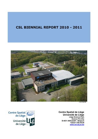
  • 1. CSL BIENNIAL REPORT 2010 - 2011 © TILT ULG DR Centre Spatial de Liège Université de Liège Liège Science Park Avenue Pré Aily B-4031 ANGLEUR – Belgium +(0)32 4 382.46.00 www.csl.ulg.ac.be
  • 2. 2 CSL Biennal Report 2010-2011
  • 3. TABLE OF CONTENT TABLE OF CONTENT ........................................................................................................................................................... 3 FOREWORD ....................................................................................................................................................................... 5 CSL IN A FEW FIGURES ....................................................................................................................................................... 8 LABORATORIES ................................................................................................................................................................ 10 1. TESTS FACILITIES LABORATORY ( RESP. I.TYCHON ) ...................................................................................... 10 Works performed during the period 2010-2011........................................................................................................ 14 Focal 1.5 chamber ................................................................................................................................................... 14 Focal 2 chamber ...................................................................................................................................................... 15 Focal 3 chamber ...................................................................................................................................................... 16 Focal 5 chamber ...................................................................................................................................................... 20 Focal 6.5 chamber ................................................................................................................................................... 24 Vibration Facilities ................................................................................................................................................... 26 Maintenance and Facility Upgrade .......................................................................................................................... 33 External activities .................................................................................................................................................... 33 2. OPTICAL DESIGN & METROLOGY LABORATORY ( RESP. Y. STOCKMAN ) ........................................................ 36 The competences..................................................................................................................................................... 36 Major events in 2010 and 2011................................................................................................................................ 38 SEE DESCRIPTION PAGES 13 AND 14. ..................................................................................................................................... 45 Optical Design Workshop ........................................................................................................................................ 45 3. LASERS & NDT LABORATORY ( RESP. M. GEORGES ) ................................................................................... 47 The team................................................................................................................................................................. 47 The competences..................................................................................................................................................... 47 Major equipment .................................................................................................................................................... 48 4. SIGNAL PROCESSING LABORATORY ( RESP. C. BARBIER )............................................................................. 53 OpticaSAR (Synthetic Aperture Radar) image processing. ......................................................................................... 53 Optical and spectral data processing ....................................................................................................................... 53 Training................................................................................................................................................................... 53 5. THERMAL & MECHANICAL DESIGN LABORATORY ( RESP. P. JAMOTTON)....................................................... 58 GSE facilities advanced thermal test environment designed upon requirement. ........................................................ 58 Extended capabilities for space condition simulation (from 5K to 400 K). .................................................................. 58 Cryogenic expertise. ................................................................................................................................................ 58 Solar systems to increase energy concentration and spacecraft/payload thermal efficiency and autonomy ............. 58 Space payload mechanism Design ........................................................................................................................... 58 6. SURFACE ENGINEERING LABORATORY ( RESP. K. FLEURY ) ........................................................................... 61 Surface coating for space applications ..................................................................................................................... 61 Surface micro texturing ........................................................................................................................................... 61 Laser ablation process ............................................................................................................................................. 61 Ion Beam Polishing .................................................................................................................................................. 61 7. ELECTRONICS LABORATORY ( RESP. N. MARTIN ) .......................................................................................... 64 8. QUALITY ASSURANCE LABORATORY ( RESP. V. DESCAMPS ) .......................................................................... 68 Detection of organic contamination by infrared spectroscopy .................................................................................. 68 Monitoring of particle contamination ...................................................................................................................... 69 PROGRAMMES ................................................................................................................................................................ 71 1. TEST PROGRAMMES ( RESP. C. GRODENT ) .................................................................................................. 71 2. SPACE SYSTEM PROGRAMMES (RESP. E. RENOTTE )...................................................................................... 77 3. TECHNOLOGY PROGRAMMES ( RESP. JH LECAT ) ........................................................................................... 85 Interreg Projects ..................................................................................................................................................... 88 4. QUALITY MANAGEMENT ( RESP. M. THOMÉ).................................................................................................... 91 European Space Agency........................................................................................................................................... 91 ISO certification ....................................................................................................................................................... 91
  • 4. AWARDS .......................................................................................................................................................................... 92 ACADEMIC ACTIVITIES ..................................................................................................................................................... 93 LECTURES GIVEN BY CSL SCIENTISTS AND PROFESSORS AT ULG ..................................................................................................... 93 LECTURES FOR EXTERNAL CUSTOMERS .................................................................................................................................... 95 SEMINARS / CONFERENCES ORGANIZED BY CSL ........................................................................................................................ 96 MASTER THESES............................................................................................................................................................... 97 PHD THESES ................................................................................................................................................................... 97 ON GOING PHD THESES ..................................................................................................................................................... 98 TRAINEE PROGRAMS ......................................................................................................................................................... 99 PUBLICATIONS ............................................................................................................................................................... 101 INTERNATIONAL RELATIONSHIP .................................................................................................................................... 108 PUBLIC OUTREACH......................................................................................................................................................... 109 VISITS .......................................................................................................................................................................... 109 SCHOOLS ...................................................................................................................................................................... 109 ASSOCIATIONS ............................................................................................................................................................... 109 EXHIBITIONS .................................................................................................................................................................. 110 PARTICIPATION TO EXTERNAL COMMITTEES ................................................................................................................. 111 BOARDS ......................................................................................................................................................................... 112 RUNNING PROJECTS ...................................................................................................................................................... 113 COMMENTS ................................................................................................................................................................... 115 4 CSL Biennal Report 2010-2011
  • 5. FOREWORD T. Chantraine General Manager For CSL, the two former years were definitely transitional. On the external side, CSL faces a profound mutation of its environment. Space exploration is not any more a reserved area for the lone scientists. Access to space became a strategic goal for the emerging nations and a commercial playground for big aerospace companies. Orders providers have changed and the role of the space agencies considerably evolved. Remember. In the 90‟s, the European Space Agency was directly coordinating the design and the integration of satellites and payloads. Today, those works are globally contracted to the industry. In the same kind of logic, this is an industrial joint-venture which operates the historical ESTEC Test Centre since 2000. The participating companies are both CSL competitors. Like it or not, space is now a market, still surrounded by several guides of geographical redistribution, but more and more led by profit, competition and risk reduction. CSL has to consider this situation very seriously, and it will. Internally, this biennial was quite turbulent too. During this period, CSL proceeded to a strong reengineering under the University supervision authority. The management processes and the global strategy were scrutinized through this work, which end up with the definition of a brand new organization headed by a straight vision: • CSL is a high level Research Center of the University of Liege devoted to applied research and managed as a “profit center”. • CSL performs Research Technology Development & Innovation (RTDI) activities mainly related to space. • CSL commits to be a significant actor of the regional economical development. • CSL nourishes a state of the art research related to space sciences within the University of Liege. CSL Biennal Report 2010-2011 5
  • 6. This statement clearly beacons CSL missions on a route linking deep science to space system development and technology swarming (through applications, expertise and high level training for instance). The inner matrix organization designed to support this activity also aims to yield a dual objective: 1. to provide a better visibility of the technological excellence areas of CSL and to clarify responsibilities as well as points of contact throughout the organization. 2. to reinforce and to improve our marketing activity. T. Chantraine I. Laven General Manager Assistant P. Rochus C. Bertrand (DGM) Academic & Scientific Finance, HR, Affairs Administration A. Cucchiaro Official Representative S. Habraken Ch. Bertrand Scientific Advisor H.R. J. Bernier Contract Office M. Thomé F. Duchateau Industrial PA/QA Accounting Cooperation Signal Electronics Surface Lasers & Optical Design Mechanical Test Quality Processing N. Martin Engineering NDT & Metrology & Thermal Facilities Lab A. Castias Ch. Barbier K. Fleury M. Georges Y. Stockman Engineering I. Tychon V. Descamps Administration P. Jamotton Test Programmes Ch. Grodent Ch. Bertrand Facility & Logistics Space System Programmes Fr. Collard E. Renotte I.T. Technology Programmes J-H. Lecat Note that this organization includes a specific academic and scientific director. This marks our strong anchorage to the Liege University and shows our willingness to keep a high level of scientific excellence using the enormous competence reservoir of the institution. You will find many traces of this excellence all along those pages as CSL carried out complex and innovative projects within the 2010-2011 period. Those works allowed CSL to maintain an international reputation and to join prestigious consortium preparing the future of the space exploration. From that prospective, the announcement in October 2011 of the Solar Orbiter selection for the M1 slot of the ESA Cosmic Vision program was a major event for us. 6 CSL Biennal Report 2010-2011
  • 7. Solar Orbiter is an extremely challenging mission crafted to stare closely at the sun. In this project, CSL owns the PIship of the Extreme Ultra-Violet Imager (EUI) and participates to the design and integration of the HI instrument. With this program, CSL consolidates a leading position in scientific system development and secures a substantial workload for the five coming years. This success combined to the dynamic we expect from the new organization allows us to get a real ambition of growth. This report will show you that this ambition stands on robust foundations. Thierry Chantraine CSL Biennal Report 2010-2011 7
  • 8. CSL in a FEW FIGURES 8 CSL Biennal Report 2010-2011
  • 9. CSL Biennal Report 2010-2011 9
  • 10. LABORATORIES 1. Tests Facilities Laboratory ( Resp. I.Tychon ) 6 vacuum chambers from 0.25m to 6.5m diameter, capable of extended vacuum and thermal cycling, equipped with optical bench laying on seismic device (vibration decoupling ). Vibration shakers ( 5 – 3000Hz , 80 -200KN ) Possibility of cryovibrations. The team The team consists in 7 persons who are presented in the following organization chart. Isabelle TYCHON Scientific team Technical team Isabelle DOMKEN Martin BROEN Sylvie LIEBECQ Josiane VERSTRAELEN Ghislain VAN aUBEL Robert SCHETTER 10 CSL Biennal Report 2010-2011
  • 11. The CSL performs various qualifications on space instruments or equipments by submitting them to environmental space conditions. The two main types of test campaigns are : - thermal vacuum qualification, - vibration qualification. A specific facility has also been developed at CSL to allow a mixed full validation : vibration under vacuum at cryogenic temperature. This facility is called „Cryovibration Test Facility‟. Generally, when thermal vacuum conditions (hot or cold cases) are imposed on an optical instrument, optical stimuli are simultaneously injected in order to validate the global optical performance in space conditions. Some specific instruments require a cryogenic environment (4.2K – 20K). This can be achieved with cryogenic techniques involving liquid Helium. The key specific CSL competencies in the test laboratory are : thermal and vibration control, cryogeny and optics. Thermal Vacuum campaigns CSL performs various qualification thermal vacuum test campaigns using its own thermal vacuum chambers with associated thermal systems. Gaseous nitrogen (GN2) is generally used to feed thermal panels with an automatically adjusted temperature in the [-150°C, +100°C] range. For specific colder temperatures, liquid nitrogen (LN2) is also used. Three types of campaigns are generally proposed: Bake-out and outgassing tests: a controllable warm up is imposed in a specimen during a specified period under vacuum to evaporate contaminants and to obtain a perfectly clean instrument. Any contamination risk must be indeed eliminated to avoid any optical performance degradation. Thermal cycles : this kind of test simulates the “in-orbit” extreme conditions with a succession of cold and hot temperatures. The instrument under test should survive to non- operating temperatures while performance should comply within the operating temperature range. Thermal balance tests : Specific radiative / conductive thermal conditions are imposed on the test specimen to simulate a stable environment as it will be seen in orbit during the operational phases. Artificial thermal gradients can be introduced in the instrument and the subsequent performance degradation is measured. Additionally the measured temperature cartography is compared with the corresponding thermal predictions. All the parameters (pressure, temperature, LN2 level) are monitored and recorded during the test campaigns. All these key data can also be analyzed in real time via a dedicated secure web connection. The CSL chambers are all equipped with a perfectly stable optical bench, fully decoupled from external parasitic vibration perturbations. All benches are connected to massive seismic blocks. Microvibration levels can be measured in real-time with specific seismic accelerometers. For specific test campaigns of space instruments working in the millimeter or sub-millimeter wavelength range, a cryogenic environment is mandatory to reduce the own radiation of the tested instrument itself. Two Helium liquefiers / refrigerators can dispatch the cold fluid to obtain environmental temperatures below 20K (4.2K for liquid Helium bath). CSL Biennal Report 2010-2011 11
  • 12. Finally, a global test campaign must always be conducted in a perfectly clean environment from the preparation phase to the final packing. This is managed by the cleanliness control section. The assembly and integration are realized in one of the two CSL clean rooms (ISO 7 as a baseline and ISO 5 cleanliness upon request). The level of cleanliness is permanently controlled via dedicated equipments like particle contamination samples (PFO), molecular contamination samples (FTIR), Airborne Particle Counter, etc….Under vacuum, the level of contaminants is monitored in real time via RGA (Residual Gas Analyzer) or TQCM (Temperature Quartz Controlled Microbalance) while a LN2 cold panel (cold trap) is permanently activated. CSL vacuum chambers and cryovibration facility Focal 1.5 Focal 2 Focal 3 Focal 5 Focal 6.5 Cryovibration chamber connected to the shaker 12 CSL Biennal Report 2010-2011
  • 13. CSL Helium Liquefiers / Refrigerators KOCH 1630 Helium Liquefier/Refrigerator LINDE TCF20 Helium Liquefier/Refrigerator CSL Biennal Report 2010-2011 13
  • 14. Works performed during the period 2010-2011 Focal 1.5 chamber Several small thermal tests have been performed in the chamber Focal 1.5 in 2010-2011 among which : Solar Orbiter Sun Sensor ( ESA ) The goal of the project is to select, adapt and qualify the sun sensor for the Solar Orbiter platform. CSL will demonstrate that it will be operational under the extreme environmental conditions due to the close proximity of the satellite with the Sun (0,25 AU). The extreme solar flux encountered during the mission lifetime required to develop sophisticated thermal protections for the complete satellite, such as front heat shield, thermal baffles and cooling radiators. The sun sensor is a crucial element for ensuring the pointing of the platform which is essential for the overall thermal control of the mission. This project is run for ESA with the Lambda-X company as prime. CSL is involved in the thermal aspect and the qualification of the system. TNO-TPD sensor The modified Sun Sensor from TNO has been tested in Focal 1.5 under 13 solar constants. Solar Orbiter EUI ( started in 2006) See a more detailed presentation on page 39 The aim of the tests in Focal 1.5 performed in 2011 concerned the thermo optical characterization of the entrance filters. List of Vacuum tests in Focal 1.5 – 2010/2011 CLS Blank tests VINCI Valve June to September 2010 September 2011 Customer : ESA Customer : Techspace Aero Sunsensor Solar Orbiter filters October to November 2010 November to December 2011 Customer : CSL (end customer: ESA) Customer : CSL (end customer: ESA) 14 CSL Biennal Report 2010-2011
  • 15. Focal 2 chamber The main activities in the 2010-2011 period of time are related to the optical validation of the TanDEM X_TLA. TanDEM-X_TLA A blank test campaign for the Tandem-X telescope has been performed in March 2010. The purpose was to measure its optical performance via interferometric method at various operating temperature. The Telescope Assembly (TLA) is a small telescope used as the optical antenna of an optical terminal. It can be used for transmission and for reception. It has been asked to CSL to perform the thermal cycling test of the TLA (QM and FM model) and to measure its optical performances under vacuum for different thermal cases. . Set up integration in the chamber TLA overview List of Vacuum tests in Focal 2 – 2010/2011 TANDEM-X Blank test March 10 Customer: RUAG Switzerland TANDEM-X _TLA QM October 10 Customer: RUAG Switzerland TANDEM-X _TLA_FM November 10 Customer: RUAG Switzerland CSL Biennal Report 2010-2011 15
  • 16. Focal 3 chamber 2010 ALADIN-Bakeout tests on permacell, MLI, STRO, tedlar for EADS Astrium SAS February – June 2010 Aladin is an instrument containing a UV high fluence laser The laser beam when crossing outgassing product can produce Laser Induced Contamination (LIC) on the optics, especially in vacuum. The materials identified from the beginning (from literature) as being the most dangerous for the LIC problem are the silicone and the aromatics. A test campaign on materials behavior with respect to LIC has been conducted by ESA to identify those not to be used. It has shown that a large number of materials cause LIC at 355nm The telescope is the last part of Aladin where the emitting path of the UV laser is crossing optical parts under vacuum. Some individual parts have already been baked (MLI, structure) but not all of them and the telescope integration has added some other material which outgassed. It is why in order to reduce as far as possible, the amount of outgassing material in the vicinity of the M2 and the TRO window, it has been agreed to perform a bake out at telescope level. Metalic parts bakeout Permacel bakeout Kapton bakeout Tedlar bakeout 16 CSL Biennal Report 2010-2011
  • 17. OLCI-Wheel bakeout tests & cycling on calibration wheel FM For Thales September 2010 – November 2010 Within the Sentinel 3 components, there is a multi-spectral optical imager for Ocean and Land Colour operational applications (with equivalent ENVISAT MERIS baseline performance), named OLCI (Ocean and Land Colour Imager). The OLCI instrument embarks a Calibration Assembly, made of a positioning mechanism and the appropriate reference diffusers which is the purpose of the current project. The overall OLCI is composed of the structure equipped with the units necessary for all functions and with the thermal hardware. All optical elements are supported on a stable flat panel (optical bench). Other equipments are distributed on the other panels. Five identical cameras point to the Earth, Eastwards and Westwards from the sub-satellite point. The Calibration Mechanism is mounted on the Instrument Earth side. In this project, CSL is responsible for the design, manufacturing, verification, calibration and delivery of the Calibration Assembly that is composed of the Calibration Mechanism and the Calibration Hardware. This work is performed in collaboration with CSEM that acts as a sub- contractor of CSL. The work of CSL is divided in two units: the calibration mechanism and the calibration hardware. OLCI wheel bakeout OLCI calibration wheel cycling test 2011 CSL Biennal Report 2010-2011 17
  • 18. AIS Gapfiller Vesselsat-1 for Luxspace August 2011 AIS, or the “Automatic Identification System” is a technology embarked on all vessels above 299 GRT, which is used as anti-collision system. Many coastal countries have established shore based receiving stations to monitor the vessel traffic. However, the reach of these stations is limited to more or less 100 nautical miles. Satellite AIS is a new emerging technology that provides a cost effective solution for monitoring vessel traffic and the individual positions of ships around the world. Such vessel monitoring information is of particular interest to ship owners and port authorities but raises also expectations to be useful for supporting maritime policy and the creation of maritime awareness information. Satellite AIS is considered as an add-on to the coastal stations that extends the vessel monitoring capability for safety and security aspects to a global scale for both the institutional and private sector. The microsatellite has been cycled between 0 and +60 °C in August 2011 AIS Gapfiller Vesselsat in the cycling test configuration 18 CSL Biennal Report 2010-2011
  • 19. Codechamps : bakeout of three encoders October 2011 Bake-out of 3 encoders at +85 °C MSI Diffuser ( Multi Spectral Instrument ) for CSL ( end customer EADS ASTRIUM SAS ) October 2011 In the framework of the Global Monitoring for Environment and Security program (GMES), ESA develops Sentinel-2, a multispectral optical imaging system for Earth Remote Sensing with terrestrial applications providing continuity and enhancement to Landsat and SPOT type missions. The diffuser is a sun-light diffuser used for absolute radiometric calibration of all spectral channels. The calibration is typically performed once a month when flying over the North Pole. During calibration phase, a mechanism deploys the diffuser in front of the instrument. The sun diffuser covers the full field of view. All the diffusers have been baked till 80 °C during 72 hours in a dedicated set up MSI diffusers integration for bakeout View of diffusers List of Vacuum tests in Focal 3 – 2010/2011 Baking Aladin permacell, MLI, tedlar, STRO CODECHAMP – Bakeout 3 encoders February – July 10 September-October 11 Customer: CSL (end customer: Customer: Codechamp Astrium) OLCI – wheel bakeout GAIA RVS – blank test for cycling test September 10 October 11 Customer: CSL (end customer: TAS-F) Customer : Astrium SAS( France) OLCI calibration mechanism cycling MSI diffusers – Blank test & bakeout tests November 10 October 11 Customer: CSL (end customer: TAS-F) Customer : CSL (end customer: Astrium) Luxspace – AIS Gaspfiller -cycling Augustus 11 Customer : Luxspace CSL Biennal Report 2010-2011 19
  • 20. Focal 5 chamber 2010 ALADIN For EADS Astrium SAS February - June 2010 In 2010, the activities in Focal 5 were principally based on the ALADIN project. Four tests have occurred for the ALADIN: a blank test of the thermal tent, a blank test for the LIC test, a bakeout of the Aladin telescope and the LIC test, between January and July 2010. The ALADIN Telescope has been installed inside the Focal 5 chamber and, once the vacuum is obtained, the high powered laser is activated by EADS and LIC measurements are performed on optical samples. Various trials have been done to finally obtain an acceptable and compliant test set-up Integration of the Telescope on Focal 5 Preparation Phase bench (ISO5 cleanliness) All the bake-out tests were permanently controlled with TQCM All the suspected contaminants like metallic staples, Kapton scotch and glue, Aluminium parts, Kapton foils, Mechanical items not perfectly cleaned have been previously baked in the Focal 3 chamber before their integration in the ALADIN configuration. OME STRUCTURE SENTINEL 3 for Carbo FibreTec GmbH November-December 2010 Additionally to the ALADIN activities, a bakeout test has been performed on the Sentinel 3 SLSTR OME structure, for the company CarbiFibertec GmbH 2011 EHP ENMAP for EHP ( EuroheatPipes ), Belgium –end customer Astrium SAS-France February-March 2011 A cycling test on LHP (Loop Heat Pipes) of the satellite ENMAP instrument (Environment Mapping and Analysis Program). 20 CSL Biennal Report 2010-2011
  • 21. Rear face of the LHP LHP integration in Focal 5 MSI STRUCTURE for APCO June - September 2011 In the summer 2011, three tests have been performed on the MSI project, for the APCO company, a bakeout of the Heat sink, the MSI structure Blank test and the MSI PSA (Primary Structure Assembly) coupled with a bakeout of several test MLI. PSA integration in the thermal tent MLI bakeout set up PSA overview CSL Biennal Report 2010-2011 21
  • 22. HOLODIR Thermal IR digital holography for non-contact surface metrology for ESA September-October 2011 See a more detailed presentation on page 49. TPV -Thermo-mechanical qualification of the Target Projector for Videogrammetry for ESA November-December 2011 The thermo-mechanical qualification aimed to demonstrate the thermo-mechanical stability and design performance in the operating temperature range. The TPV system was tested in the thermal vacuum facility FOCAL5.The TPS was submitted to a varying temperature (hot and cold cycle) and viewing permanently an object at 5 m. As required by ESA the centroidisation was stable within 10 minute of recording and achieved a plane stability of better than 0.1 mm. Isometric view of the thermal set up in FOCAL 5 Side view of the FFOV projector mounted on its X95 rail on the optical bench of Focal 5 (MLI not yet installed) 22 CSL Biennal Report 2010-2011
  • 23. Shroud temperature of the SFOV projector head. Blue=>Front panel, Red=>Shroud around projector, Green=>Front lens temperature. Dot pattern of the SFOV observed by the camera. The object is black coated radiative shroud. One notices some highly reflective areas which are due to the MLI. There are 3 apertures in the shroud covered with MLI. Some highly reflective points are due to screws. A strong loss of contrast is observed, due to reflections of the MLI tent on the shroud. List of Vacuum tests in Focal 5 – 2010/2011 2010 ALADIN – BT Shroud ALADIN – LIC test January 2010 May-June 2010 Customer: EADS Astrium SAS Customer: EADS Astrium SAS ALADIN – BT LIC test Baking OME structure February 2010 November-December 2010 Customer: EADS Astrium SAS Customer: Carbo fibreTec, GmbH ALADIN – Telescope bakeout March 2010 Customer: EADS Astrium SAS 2011 GAIA RVS – baking thermal tent MSI – Structure Blank Test January 2011 June 2011 Customer: EADS Astrium SAS Customer: APCO, Switzerland CSL Biennal Report 2010-2011 23
  • 24. EHP EnMAP – Cycling test MSI – PSA cycling and Bakeout MLI February-March 2011 Augustus-September 2011 Customer: EHP Belgium (final Customer: APCO, Switzerland customer : EADS Astrium SAS) Holodir MSI – Heat sink bakeout September-October 2011 June 2011 Customer: ESA Customer: APCO, Switzerland TPV November-December 2011 Customer: ESA Focal 6.5 chamber GAIA PLM- AC FLAT Stabilisation for EADS – Astrium SAS June 2011 Another test for the GAIA programme was the stabilisation measurement under vacuum of the AC Flat (for the GAIA PLM configuration foreseen in the summer 2012). The optical stability requirements of the GAIA PLM was so stringent that an additional bench, called TVIS (Thermal Vacuum Interface Structure) has been designed and manufactured under the CSL responsabilities, coupled with 3 isolator‟s with their own damping elements. The GAIA AC Flat test campaign has been divided in two parts: the isolator‟s final acceptance test and the GAIA AC Flat vacuum test. The goal of this GAIA test campaign was to : For Astrium : - Validate the simulation model - Find the different contributors in the perturbation environment - Validate the transport of one AC Flat fixed on its mechanism AFMA - Validate the AC Flat control loop in the configuration at CSL For CSL : - Validate the procedure for the isolators and the TVIS handling GAIA AC FLAT integration TVIS preparation with dummy masses and one AC Flat 24 CSL Biennal Report 2010-2011
  • 25. View of an isolator with its damping element Compressed Isolator with seismic measurement system Additionally to these GAIA campaigns (DSA and AC Flat), the Focal 6.5 was also used in 2011 to cycle the OLCI mechanism QM model and to perform a bakeout of the thermal tent dedicated to the cycling test on GAIA RVS. OLCI mechanism preparation for cycling test OLCI mechanism preparation for cycling test List of Vacuum tests in Focal 6.5 – 2010/2011 GAIA DSA OLCI QM Mechanism- cycling test November-December 2011- Jan & Augustus 2011 March 2012 Customer: Thales Customer: Sener- Spain GAIA RVS- thermal tent for cycling test GAIA PLM – AC FLAT stabilisation bakeout measurements October 2011 June 2011 Customer: EADS Astrium SAS Customer: EADS Astrium SAS GAIA DSA pre and post vibration thermal test November 2012 Customer: Sener – Spain CSL Biennal Report 2010-2011 25
  • 26. Vibration Facilities The qualification vibration campaigns simulate the mechanical environmental constraints observed by an instrument during launch conditions. Simulating Sine, Random or Shock levels can be imposed on any structure with one of the two CSL shakers. 2016U 88kN CSL shaker 4522LX 200kN CSL shaker 2010 : 2016 U only MIRI IOC For OIP - March 2010 26 CSL Biennal Report 2010-2011
  • 27. VISCAL for TNO October 2010 OLCI CA QM for CSL (end customer Thales) - December 2010 – June 2011 CSL Biennal Report 2010-2011 27
  • 28. 2011 2016 U MSI_VNS Detectors for XENICS - April 2011 PROBA-V Detectors for XENICS - August 2011 MSI SWIR2 and VISNIR Detectors for XENICS - October 2011 28 CSL Biennal Report 2010-2011
  • 29. Vesselsat-1 for LUXSPACE - July 2011 CSL Biennal Report 2010-2011 29
  • 30. Vesselsat-2 for Luxspace - November 2011 Pathfinder-3 for Luxspace - December 2011 30 CSL Biennal Report 2010-2011
  • 31. GAIA BAM OMA PFM Bar#1 and Bar#2 for TNO August 2011 – September 2011 Bar #1 Bar #2 CENAERO : Triade November 2011 The aim of these tests is to check and measure the impact of the smart tag gluing on the structural integrity, under thermal and vibration aeronautic conditions, in order to validate and update the CENEARO simulation results. The article to be tested is a dummy smart tag: (a structural model of the smart tag) glued on a structure sample. Material is Prepreg UD; 8552 IM7 (Supplier HEXCEL); Approximative composition is: 60% CFC Fibre and 40% Epoxy Resin. CSL Biennal Report 2010-2011 31
  • 32. 4522 LX PROBA-V STM3 for OIP - October 2011 GAIA DSA for SENER - November 2011 Extra test Physiol – Sirris : Fatigue test on intraocular lenses 32 CSL Biennal Report 2010-2011
  • 33. Maintenance and Facility Upgrade Apart from periodic planned maintenance activities, CSL proceeded to two specific main significant replacements during the 2010-2011 period. Automatisation Test in Focal 2 After the installation of the new thermal system in Focal 2 by the CSL team (ended in 2010), an automatisation blank test has been performed in the chamber (April 2011) with 5 independent lines controlled at different temperatures. The bakeout mode has also been tested. After this test, all the thermal systems of the other CSL facilities have been upgraded to allow future automatisation tests (end of this upgrading in 2012). Thermal tent preparation for the Thermal tent in Focal 2 automation blank test External activities MSI FPA For the MSI FPA (Focal Plane Assembly), CSL has been in charge to provide new thermal panels and electrical flanges with Sub D feedthroughs. The panels have been baked and instrumented at CSL before delivery at EADS Astrium. CSL Biennal Report 2010-2011 33
  • 34. LSS LN2 pumps control cabinet design and manufacturing The test department has developed all the CSL internal facilities and related equipments. This competence in thermal and vacuum engineering techniques is now proposed for external customers as well. ESA has asked CSL to design and install a new control cabinet of the LSS (Large Space Simulator facility at ESTEC) LN2 pumps . Additionally to this cabinet, CSL has also replaced the thermal system valves , the pumps and a new insulation of the thermal system. The installation has been done in the summer 2010. Control cabinet Control cabinet 34 CSL Biennal Report 2010-2011
  • 35. General overview of the new installation CSL team during installation CSL team during installation CSL Biennal Report 2010-2011 35
  • 36. 2. Optical Design & Metrology Laboratory ( Resp. Y. Stockman ) Innovative optical and spectral payloads ( up to 15 CSL instruments in space ). Optical system calibration in space condition ( including cryo ). Optical metrology. BRDF calibration. Optical instrument and assembly models and design. The Team The team consists in 9 people who are presented in the following organization chart. Dr Yvan Stockman Ir Hallain Ir Hellin Marie Ir Mazzoli Ir Hermans Aline Dr Loicq Jérome Ir Mazy Emmanuel Marcotte Sarah Dr Ir Roose Steve Jean Philippe Laure Alexandra Project control Optical scientist Optical engineer Optical technician Optical engineer Project Manager AIV Optical design The competences Metrology is a key activity for all what concerns optical payload testing. Since the 70's, CSL develops Optical Ground System Equipments (OGSE) for testing scientific payloads operating from the X-rays until the sub-mm wavelengths. To provide efficient and up-to-date technology, the group develops new instruments and new metrology methods to face the upcoming demands. The knowhow and expertise acquired on these developments are now exploited for in-flight metrology to on-ground industrial metrology support. The optical design activities support all CSL projects involving optical simulations as well as optical design and optical simulation for external customers. 36 CSL Biennal Report 2010-2011
  • 37. The "Optical design and metrology" group activities cover the following: - Development of Optical Ground Support Equipment - Development of new metrology tools - Development of flight metrology instrumentation - Support to industry in metrology problems - Perform optical design and analysis The labs The following S/W are available: CODE V, ASAP, FRED, IDL, Intelliwave. Several labs are available and dedicated for different purposes: One lab for WFE measurement, Two labs with optical table for the development of optical experiment One optical table in a class 100 for OGSE integration One BRDF bench in class 100 The next table lists available metrology tools that are managed by the team. H/W Wave Front Sensors MiniFiz Phase temporal shifting visible interferometer HS 2000 interferometer simultaneous phase shifting IR high spatial resolution interferometer Hartman WF sensor + beam expander Topology instruments 3D topology profilometer Wyko profilometer Metrology instruments T5000, T3000A & TC2002 (+ T2 and T3) theodolites with ECDS3 software 2 * HP Interferometer GOMfringe projection and Digital image correlation Thermometry instruments FLIR S45 and Infratec Thermographic cameras Pyrometre Collimators F/10 Newton 300 mm diameter WFE 63 nm F/5 Off axis 400 mm WFE 63 nm Monochromators and spectrometer Mc Pherson Rowland 1 m Mc Pherson Czerny Turner 0.3 m Optotronics Spectometre Hamanatsu CSL Biennal Report 2010-2011 37
  • 38. Basic tools & S/W Cameras Optical tables Softwares : IDL, ASAP, CODE V, INTELLIWAVE, FRED Other tools BRDF bench Imaging AC flat 700 mm on 2 axis Parbolic mirror 400 mm of axis parabola from Athol 2 * 400 mm flat mirror from Athol 2 * 300 mm flat mirror (Hipparcos & XMM) 2 Autocollimator /µRadian + 1 Nikon X-rays source EUV collimator 800 mm EUV collimator 440 mm X-ray off axis parabola collimator Major events in 2010 and 2011 These activities are illustrated in the next table listing the major events of the years 2010-2011. A next paragraph presents a small description of the major events. 2010 events 2011 events End of End of PROBA III Startiger PROBA V straylight analysis Projects running Projects running Space & ground imaging in astronomy Space & ground imaging in astronomy Tip Top Lam Tip Top Lam Multiphy Multiphy Target for videogrammetry Target for videogrammetry Coarse Lateral Sensor (CLS) Coarse Lateral Sensor (CLS) Large deployable telescope Large deployable telescope Optical consultancy Optical consultancy BRDF characterisation of solar diffusers for BRDF characterisation of solar diffusers for Sentinel-2 & Sentinel-3 Sentinel-2 & Sentinel-3 PROBA V straylight analysis ACTIO Start of Start of ACTIO PROBA V GSE SOLO EUI SOLO HI/WSPR 38 CSL Biennal Report 2010-2011
  • 39. Major events Solar Orbiter EUI (started in 2006 and has been selected in 2010 in the ESA Comic Vision program) The EUI (Extreme Ultraviolet Imagers) instrument suite onboard the ESA Cosmic Vision Class-M Solar Orbiter candidate mission is composed of two high resolution imagers (HRI), one at Lyman α and one dual band at the two 17,4 and 33,5 nm EUV pass bands in the extreme UV, and one dual band full-sun imager (FSI) working alternatively at the two 17,4 and 30,4 nm EUV pass bands. In all the units, the image is produced by a mirror-telescope, working in nearly normal incidence. The EUV reflectivity of the optical surfaces is obtained with specific EUV multilayered coatings, providing also the spectral selection of the EUV units. The spectral selection is complemented with very thin filters rejecting the visible and IR radiation. Due to its orbit, EUI / Solar Orbiter will be irradiated to 20 solar constants and an entrance baffle to limit the solar heat input into EUI is needed. The CSL is the PI Institute of the EUI Consortium including members from Belgium, France, Germany and United Kingdom. Solar Orbiter launch is planned in 2017/2018. Solar Orbiter EUI instrument suite (Dec. 2009) The optical design of the High Resolution Imager is performed by the CSL optical design workshop. This telescope makes an image of a portion of the sun. One pixel sees a surface of sun equal to 85 x 85 km².The main activity was a tradeoff between different designs depending on the minimum distance to the sun; between 0.2 and 0.3 AU : - modification of the focal length, Solar Orbiter HRI optical design - increase of the entrance pupil diameter. SOLO HI and WSPR Started 2011 – end 2013 Prodex SOLO HI is an instrument on board of the SOLO solar mission proposed by R. Howard from NRL (US). The CSL activities consist in the optical design, BRDF measurement on samples and straylight evaluation on a demo and on the FM. CSL Biennal Report 2010-2011 39
  • 40. PROBA V ESA via Industry Started 04-07-2011 – end 2012 Proba Vegetation is a platform embarking a multispectral instrument for Earth Observation. It shall fill the gap between the Spot 5 and the Pleiades missions, with the major constraints that it can be flown on a PROBA type satellite. CSL has been involved in the straylight analysis and the performance and environment test definition of PROBA V. CSL is the subcontractor of OIP The straylight is performed by the CSL optical design workshop group. The study allows to define the baffle design. A dedicated straylight analysis on the SWIR channel identified the best chamber orientation to avoid a scattering towards the SWIR detector. PROBA V stray light analysis CSL FOCAL 3 general implementation drawing CSL contributed to the on-ground calibration study of PROBA V. The aims of the study were to define the overall calibration strategy. This on-ground characterization must address all the instrumental effects that will affect the final in-flight measurements. A complete calibration process covers a lot of parameters: radiometric, spectral, geometrical, dark signal, effects that can contribute to the instrumental response. The year 2012 will be dedicated to the realization of the proposed work. The following projects have run during 2010 and 2011 Target Projector System ESA GSTP 2008-2012 The objective of this activity is to design, develop, manufacture, install, qualify, test and deliver to ESA an operational prototype videogrammetry target projector system (TPS) for use under thermal vacuum conditions. The TPS to be developed in the frame of this activity had to be compatible and usable with the existing ESTEC videogrammetry systems (listed here in order of importance for critical design decisions) : - ESA miniaturized system (Space-X cameras, space-qualified) and for further operational application information, - ESA canister based videogrammetry system (Rollei 6008 cameras enclosed in a canister for thermal control and environmental conditioning). The TPS shall be designed to be usable in the ESA Large Space Simulator (LSS) without any thermal impact on the test item. It will maintain operational stability and precision under typical thermal-vacuum test environments to which the system will be subjected. 40 CSL Biennal Report 2010-2011
  • 41. In 2011 final functional and performance tests have been successfully carried out. The final delivery will be completed beginning 2012. Dot pattern observed by the camera. TPV projector The object is black coated radiative shroud. Coarse Lateral Sensor ESA GSTP 2009 – 2012 The objective of this activity is to develop an engineering qualification model (EQM) of a coarse lateral sensor (CLS) for the PROBA-3 formation flight with two satellites to form a giant solar coronagraph. As a goal requirement CSL will base the CLS on the heritage of existing space hardware, where only delta developments are required. The complete CLS system (optics, mechanics, electronics) will be developed and brought to a technology readiness level of 6 (i.e. System/subsystem model or prototype demonstration in a relevant environment (ground or space). CLS opto mechanical design CLS optical design elaborated by the optical design workshop The coarse lateral sensor developed at CSL is based on a camera (CMOS detector), a telecentric lens, a fiber-coupled laser-diode bar, and a corner cube. The fiber-coupled laser-diode bar emits a diverging beam, from the coronagraph satellite. A corner cube located on the occulter satellite sends the light back. This light is captured by the telecentric lens and camera, located on the CSL Biennal Report 2010-2011 41
  • 42. other satellite. A lateral shift of the PROBA-3 Occulter S/C is seen on the camera as an image displacement. Pseudo real time centroidisation algorithms, allow tracking the image position and feed the on-board computer with this information, allowing position stabilization. In 2010 the system has been build and all the required performances have been demonstrated. Nevertheless, its operation at high temperature 60°C needs to modify the CMOS support structure. These activities have been started end of 2011. Large Deployable Telescopes ESA TRP2009 – 2012 Large light-weight telescopes in space are considered as key elements enabling future Earth observation and space science. They will be needed for imaging as well as non-imaging (photon bucket) applications. The first large space telescope, “Hubble”, has an area density of about 180 kg/m2, the current generation space telescope, „James Webb Space Telescope‟ has an area density below 20 kg/m2. However, continued demand for new science and observation from space will drive the need for even larger telescope apertures. For achieving from GEO a ground spatial resolution of a few meters, telescope aperture diameters of the order of 20 m need to be achieved. This requires completely new concepts of deployable space telescopes with primary mirror area densities below 3 kg/m2. Many interesting ideas and concepts of very large and lightweight telescopes can be found in the literature. They often fall into one of the three following telescope concept groups: - 3D-shaped membrane - Flat membrane - Light-weight plates The objectives of the activity are firstly the study of various advanced concepts of large deployable space telescopes and secondly the bread-boarding of the key element(s) or heart of the most promising telescope concept in form of a demonstrator. The aim of the demonstrator will be to demonstrate (at full or reduced but representative scale) the feasibility and applicability of the selected concept and technologies for future large deployable telescopes in space. CSL is prime, with TUM (D) and ULB (B) as subcontractors. Detailed design of the demonstrator has been accomplished during 2010, while the year 2011 was dedicated to the manufacturing of these demonstrators. Example of photon sieve achieved with Demonstrator prototype build by the CSL simulator MUL and TUM 42 CSL Biennal Report 2010-2011
  • 43. Tip Top Lam FEDER 2008 – 2013 The project is led by SIRRIS and can be considered as a natural continuation of our collaboration on the TAP project on “Rapid Prototyping”. The laser cladding techniques started in the 90th. The powder used in laser cladding is normally of metallic nature, and is injected into the system by either coaxial or lateral nozzles. The interaction of the metallic powder stream and the laser causes melting to occur, and is known as the melt pool. This is deposited onto a substrate; moving the substrate allows the melt pool to solidify and thus produces a track of solid metal. This is the most common technique; however some processes involve moving the laser/nozzle assembly over a stationary substrate to produce solidified tracks. The motion of the substrate is guided by a CAD system which interpolates solid objects into a set of tracks, thus producing the desired part at the end of the trajectory. This technique reduced considerably the manufacturing time and cost. The technique takes advantage of the 3D definition of an object to manufacture layer per layer in a few hours. The CSL contributes to the selection and procurement of equipments for the real time dimensional and thermal control. The real time dimensional control is obtained by a stereo correlation technique, that indicates the thermal stresses during the cooling down, while the thermal control is ensured by a pyrometer and a IR camera. Contamination issues are also monitored through a spectrometer. 2010 and 2011 were dedicated to the integration and optimization of the metrology tools in the cladding machine. Tip Top Lam FEDER with industries in Wallonia MULTIPHY Walloon Region project in the frame of the aerospace cluster Skywin 2008-2012 This project is led by OPEN ENGINEERING and aims to develop new CAE tools that integrates in a coupled way methods and simulation in different field: aerodynamic, thermal, structural, optical, electrical and acoustical fields. CAE is presently used in all the industries for analysis and prediction of their own products. The goal of these simulations techniques are : - Reduction of the optimization time (time to market) - Increase the liability of the predicted models - Use of design optimization methods on parametric model to increase the performances. Due to the increase power capacities of the computer, there is a demand from the industry to produce simulations as close as possible from the reality. CSL Biennal Report 2010-2011 43
  • 44. This implies: - Increase in the geometrical details implies a lot of nodes - Interactions between fluid mechanics and other physical phenomena as mechanical, thermal, vibro and aero acoustical - Other electromagnetic interactions, optics, radiation, … The goal of the project is to reply to the need of the industry based on the necessity to use a new generation of S/W based on problem of large dimension integrating new multiphysics coupling. The major contributions of CSL in this project are to handle the optical problems and models, and to demonstrate experimentally the multiphysics coupling announced by the model. To achieve this, CSL developed several test benches, one opto-thermo-mechanical case with a spherical lens fixed in an aluminium barrel, which is the simplest structure found in an opto- mechanical system. In this study, material characteristics are assumed to be well known: BK7 and aluminium have been retained. Temperature variations between 0 and +60°C from ambient have been applied to the samples. The second system is an opto-thermal bench consisting in a YAG laser rod heated by means of a dedicated oven. The thermo-elastic distortions impact on the optical performances has been measured using a Fizeau interferometer. For the YAG bar, birefringence and polarization measurements have also been performed using a polarimetric bench. The tests results have been compared to the predictions obtained by OOFELIE Multiphysics which is a simulation software dedicated to multiphysics coupled problems involving optics, mechanics, thermal physics, electricity, electromagnetism, acoustics and hydrodynamics. From this comparison modeling guidelines have been issued with the aim of improving the accuracy of computed thermo-elastic distortions and their impact on the optical performances. Polarimetric Test set-up Measured WFE at T=20.5°C and 57.2°C at Spherical lens test bench lens center and remainder from their subtraction Space and ground-based imaging in astrophysics (2007 2012) CSL participates to this ARC (Action de Recherche Concertée) as specialist in optics and space instruments. The target of this project is to merge different teams specialized in astrophysics, optics and instrumentation in order to be prepared for the forthcoming astrophysical and space research programs. This project is run with 3 other research groups of ULg : AGO-AEOS, AGO-GAPHE and Hololab. CSL develops a compact co-phasing sensor to phase segmented mirrors space telescopes. During 2010 and 2011, a post Doc developed and tested a co-phasing Piston sensor based on phase retrieval algorithm. 44 CSL Biennal Report 2010-2011
  • 45. INPUT FILES : Pupil, PSF, Darks DISPLAYS RESULTS ACTIONS S/W interface Test bench ACTIO Walloon Region project in the frame of the aerospace cluster SKYWIN 2009 – 2014 The project goal is to follow and even anticipate the general trend in EO : - increase of the spatial resolution within the dimensional limitations of a microsatellite, - develop acceptable and space qualified solutions with commercial components. To improve the commercial attractivity of the Walloon space industry in this content, CSL will study the development of qualification and calibration of small multi- and hyper-spectral instruments. Concerning the increase in spatial resolution, new breakthrough technology will be proposed. This project started in 2009 and will be finished in February 2014. During the years 2010 and 2011, participation to the high level specification for EO has been carried out and the way to verify and calibrate these requirements has been performed. Solar Orbiter Sun Sensor (Started in 2009, ended 2011) See description page 14. Optical Design Workshop Introduction The optical design section supports all CSL projects involving optical simulations as well as optical design and optical simulation for external customers. A large part of the workshop activity was already presented here above in the different activity group reports (E.g. EUI, CLS, TPV, PROBA V, SCID). Nevertheless, the workshop deals also with project concerning only optical design generally for industry. Major examples are given hereafter. CSL Biennal Report 2010-2011 45
  • 46. Project descriptions ASPIICS StarTiger ESA (2009 – 2010) This study concerns the PROBA-3 mission, which is dedicated to the demonstration of Formation Flying (FF) technologies for future European scientific and application missions like DARWIN. The success of the envisaged missions depends on understanding and correctly implementing all the aspects of FF. The STARTIGER program addresses the study of a new generation externally-occulted solar coronagraph operating in flight formation. The instrument is distributed over two platforms separated by about 150m, and forming a giant externally-occulted coronagraph: the imaging part is hosted by one spacecraft and remains in the shadow of the external occulter hosted by the other spacecraft. This basic configuration corresponds to a "rigid" long base instrument, and in this case the formation can be considered as the instrument. This study will focus on the optical design of the coronagraph and the formation flight metrology. CSL is working with LAM as prime contractor. PROBA III Coronograph design Other studies for industrial customers Most of these studies are protected by NDA. These studies use the optical skill of the team for straylight analysis in remote systems, flux homogenisation for solar panel applications or illumination devices. Dedicated optical benches are set-up for measurements on industry demand as detector spectral response, BRDF. 46 CSL Biennal Report 2010-2011
  • 47. 3. Lasers & NDT Laboratory ( Resp. M. Georges ) Non DestructiveTesting for space system, instrument, material (holography, interferometer, IR, …) Composite non destructive characterization The team The team consists in 3 persons who are presented in the following organization chart. Marc GEORGES Scientific Team Technical Team Cédric THIZY Sara MARCOTTE Jean-François VANDENRIJT The competences The competences of the group are historically centered on laser metrology system developments, from research to pre-industrial prototyping and applications. Typical systems developed in the past are a high resolution holographic camera for non destructive testing and full-field deformation metrology, laser distance-meter, and so on. The group is also highly active in CSL Biennal Report 2010-2011 47
  • 48. applying such techniques in relationship with needs of aerospace industries: metrology for comparison with finite element analysis, flaw detection in composites, etc. Recently the group started development of innovative techniques, mainly based on speckle and holography in the Long Wave InfraRed spectrum. Basic studies were first performed and followed by laboratory breadboarding and development of portable sensor. In order to reach this high level of achievement, the group is composed of experts, highly skilled in physics, and especially in optics, and in measurement science. The group is now involved in various projects for characterizing the behavior of composite structures undergoing different kind of stresses, measurement of expansion up to 150°C and detection of flaws in composites. The group is currently studying various non destructive methods like shearography, thermography and laser ultrasounds. Major equipment 1. Three laboratories with various optical tables 2. Lasers : YAG DPSS Coherent Verdi 532 nm, 5 Watts YAG DPSS Coherent 532 nm, 500 mWatts YAG DPSS Coherent 1064 nm, 80 mWatts Ar3+ Coherent Sabre 488 nm, 5 Watts YAG Q-Switch Coherent Infinity 1064 nm (600 mJ/pulse) & 532 nm (300 mJ/pulse) YAG Q-Switch Quantel Brilliant Easy, 1064 nm (350 mJ/pulse) & 532 nm (165 mJ/pulse) Tunable diode laser New Focus, Velocity 6308, central wavelength 673 nm ± 10 nm, 2 mWatts CO2 VM-TIM, 9.5 µm & 10.6 µm, 10 Watts CO2 Access Laser Co Merit-S, 10.6 µm, 8 Watts Various He-Ne lasers for alignment 3. Vacuum chamber : 55 cm diameter, 55 cm long, with various optical windows in glass for visible applications and ZnSe for thermography. 4. Photorefractive holographic cameras for high resolution displacement measurement (CSL own development) : Optional 4 illumination for full-vector measurement Vacuum compatibility 5. Shearographic camera for flaw detection (CSL own development) 6. Thermographic cameras 7. Various excitation methods (Infrared lamps, flash lamps, etc…) Projects 48 CSL Biennal Report 2010-2011
  • 49. FANTOM : Full-Field Advanced Non Destructive Testing Technique for Online Thermo- Mechanical Measurement on Aeronautical Structures (2009-2012) Funded by European Union - FP7 CSL coordinates the FANTOM project, with a total of 6 partners. The FANTOM project aims at developing an innovative non destructive testing based on association of thermography and holographic techniques, using lasers in the thermal infrared spectrum (around 10 µm). The applications are mainly the thermomechanical behaviour assessment of aeronautical composite structures but also the flaw detection in such structures. The project has proven so far that it was possible to combine holography and thermography in a single sensor. A transportable set-up is currently under investigation for various non destructive testing applications. Tests are scheduled at Airbus premices in 2012. HOLODIR (Thermal Infrared Digital Holography for Non Contact Surface Metrology) (2009-2012) Funded by ESA - GSTP The goal of the project is to develop a novel digital holographic technique targeted at space reflector deformation measurement. It consists of a long wave infrared (LWIR) digital holographic interferometer (DHI) to measure relatively large displacements, typically 250 µm, of complex surfaces, shapes and structures under both ambient and thermal vacuum condition with a measurement uncertainty of 0.25 µm. This LWIR digital holographic interferometer provides a new measurement technique to fill the gap between holography/interferometry in the visible and techniques based on structured light illumination. The former provides a very good measurement uncertainty but requires a very stable environment, while the latter provide large measurement range but with higher measurement uncertainties. The performances of the developed instrument have first been verified in the lab by measuring tilts of a 1.1 m diameter parabolic reflector, shown in a vacuum chamber surrounded by a thermal shroud (figure (a)). The optical set-up is depicted in figure (b). The tested object is not shown but is placed on the left of the BS2 element. The set-up was designed to be partly incorporated into a vacuum chamber. Only the CO2 laser and the thermographic camera are out of the chamber of which limits are indicated by windows W. One particularity of our technique is that is makes use of a diffuser D for illuminating the tested specular objects. This allows imaging object with unusual shapes or to avoid optical components such as null-lenses, specifically designed for the reflector under test, when conventional interferometry is applied. CSL Biennal Report 2010-2011 49
  • 50. (a) (b) W CO2 LASER W The following figures show the deformation measured by LWIR Digital Holography between 288K and 113K on the parabolic reflector. These are compared to measurements that were obtained with a High Resolution InfraRed Interferometer (HRIRI) developed by CSL in the past and making use of null-lens. The results show an excellent consistency between both measurements. The next tasks are to consider more complex shapes of reflectors which cannot be measured by classical interferometry. LWIR DH measurement HIRI measurement Difference ~ 1,6 µm RMS Thermoelastic distortion verification methods for spacecraft structures (2009-2012) Funded by ESA - TRP The project aims at verifying simulation methods by finite element modeling of thermoelastic distortions which appear on spacecraft structures. Our partner EADS Astrium has selected the STM of the OSIRIS telescope, part of the current Rosetta mission. The following figure (a) shows the set-up which includes a holographic camera equipped with a device splitting the laser illumination in 4 beams which allows the measurement of full vector displacement of the specimen. This device was developed by CSL. On the upper right images (b) and (c) show typical high resolution interferograms obtained with the holographic camera developed by CSL and 2 illuminations of the 4-illumination module. The 4 interferograms obtained with each one are combined to retrieve the 3 components of displacement-vector in every pixel of the image. The lower right images show the result of the X-component of full-field displacement. Image (d) is the result of the measurement, (e) the simulated one and (f) the difference between the model and the measurement. 50 CSL Biennal Report 2010-2011
  • 51. E_COM : Engine Composite (2009-2012) Funded by Wallonia – DG06 (Marshall Plan) The project is led by Techspace Aero and aims at developing engine elements in composite. CSL has the task to perform various Non Destructive Testing methods for assessing the behavior of components under thermal loads. CSL developed various set-ups for measuring expansion of elements developed by Techspace. The following figures show facility used for heating an assembly which incorporates various materials and whose differential expansion had to be assessed in various points. The temperature of 150°C was obtained by heating the specimen (visible on the left) and temperature homogeneity was insured by insulating the whole set-up. The expansion was measured by LVDTs in 4 points distributed around the specimen. The gap (in the range of a few microns) between various segments was also measured by cameras and is also shown hereafter. ECOTAC : Efficient COmposites Technologies for Aircraft Components (2011-2014) Funded by Wallonia – DG06 (Marshall Plan) The project is led by the 3 main aerospace industries present in Wallonia: Sonaca, Sabca and Techspace Aero. It aims at developing composite structures for various aeronautics applications. CSL leads the non destructive inspection task, benchmarking different emerging non contact techniques for aeronautics, such as shearography, thermography and laser ultrasonics. Following figures present a defect present in the composite slat and which is visualized by shearography and various thermography techniques. Laser ultrasonics will be considered later. In the next phase of the project, CSL will develop further these NDT techniques. CSL Biennal Report 2010-2011 51
  • 52. 52 CSL Biennal Report 2010-2011
  • 53. 4. Signal Processing Laboratory ( Resp. C. Barbier ) OpticaSAR (Synthetic Aperture Radar) image processing. Optical and spectral data processing Training The Team The team consists in 3 persons who are presented in the following organization chart. Christian BARBIER Scientific Team Dominique DE RAUW Anne ORBAN CSL Biennal Report 2010-2011 53
  • 54. Introduction CSL activities on radar imagery processing have begun for twenty years and resulted in the creation of the "Space Environment and Remote Sensing Group". The projects are articulated onto three principal themes : - SAR PRE-PROCESSING, - SAR POST-PROCESSING, - GEOMATIC APPLICATIONS. The Space Environment and Remote Sensing group has acquired an international reputation in the field of SAR data processing; however, for various reasons independent of the quality of the team, funding has become insufficient to sustain the ambitions of the past years. Accordingly, new or refocused activities are gradually integrated in the group‟s workplan : - Keep up with SAR projects with limited budgets (WISIP, MUSAR, WIMCA) - Consolidate the existing partnership with the Royal Military Academy - Introduce new ideas in the SAR activity, e.g., bistatic and opportunistic SAR, processing. - Develop projects in the VIS / NIR / TIR (hyperspectral) instrumentation and calibration. - Develop machine vision activities based on UAV‟s for infrastructure monitoring - Space Weather, particularly in the field of Space Situation Awareness (SSA) is a new topic of research. Majors events Argentine-Belgium Cooperation : SAOCOM Project : In 1997, Belgium and Argentina signed a cooperation agreement on space, which materialized with Belgium‟s participation to the SAOCOM project, in the framework of a specific agreement signed in 2000. The responsibility of the project was attributed to Centre Spatial de Liège (CSL) under Belspo financing. SAOCOM is an Earth observation satellite system developed by CONAE (Comción Nacional de los Activitades Aerospaciales), the payload of which is a L-band full polarimetric Synthetic Aperture Radar(SAR). Two satellites are to be launched one year apart, starting end 2014. Together with the Italian Cosmo-Skymed satellites, they will constitute the X+L-band SIASGE system for disaster management. 54 CSL Biennal Report 2010-2011
  • 55. The CSL contribution to this project consist in : 1) The preparation and delivery to CONAE of the SAR interferometry (InSAR) and polarimetric SAR interferometry (PolInSAR) tools. 2) The development of a reference Stripmap/TOPSAR processor capable of handling a set of SAOCOM reference beams and imaging modes. 3) Participating in the various reviews (currently at CDR level) of the SAOCOM subsystem. CSL attended the SAR instrument CDR at CONAE premises (Buenos Aires) in September 2011. The InSAR and PolInSAR tools were delivered at the end of 2011. The Stripmap SAR processor is due for end of 2012, while the TopSAR processor shall be delivered end of 2013. An image of Buenos Aires focused by the current CSL SAR processor from ERS-1 raw data acquired at the Cordoba ground station is shown hereunder. CSL Biennal Report 2010-2011 55
  • 56. WIMCA : WIMCA is an ESA project for which we are Sub-Contractor to the University of Bari. The objective is to study, experiment and validate a new radar interferometry technique that exploits the wide- band capabilities offerred by the new-generation SAR sensors (e.g., TerraSAR-X). As a sample illustration of the results, the figure hereunder shows a 3D view of an interferometric digital terrain model, generated by the new technique from TerraSAR-X images, over the region of Uluru in Australia. An aerial view of the same site is also shown for comparison purposes. The project was completed in 2011. An extension is to be carried out in 2012. 56 CSL Biennal Report 2010-2011
  • 57. MUSAR : Passive radars use transmitters of opportunity as signal source and are necessarily bistatic. Passivity has many advantages: Built-in redundancy since any transmitter (subject to central frequency and bandwidth requirements) can be used as source; By exploiting several transmitters of opportunity, it is feasible to increase the revisit rate of a particular area; Lower cost than an active system since there is no need for a transmitter. Moreover since no signal is transmitted, there is no need for acquiring a license or obey transmit power regulations. The MUSAR project was carried out in collaboration with the Royal Military Academy. The contribution of CSL was to provide a demonstrator of frequency-domain passive bistatic SAR processor. This processor was tested on both simulated (point target responses) and real (ENVISAT) raw data. The final report was delivered in December 2011 and the final presentation took place at RMA premises in February 2012. CSL Biennal Report 2010-2011 57
  • 58. 5. Thermal & Mechanical Design Laboratory ( Resp. P. Jamotton) GSE facilities advanced thermal test environment designed upon requirement. Extended capabilities for space condition simulation (from 5K to 400 K). Cryogenic expertise. Solar systems to increase energy concentration and spacecraft/payload thermal efficiency and autonomy Space payload mechanism Design The Team The team consists in 10 persons who are represented in the following organization chart. Pierre JAMOTTON Experts Scientific Team Technical Team Jean-Yves PLESSERIA Tanguy THIBERT David BELLUZ Benoît MARQUET Thibaut HARDENNE Philippe AUTENZIO Laurence ROSSI Natanaële ROSATO Pascal BARZIN The thermal and mechanical competences of the CSL originally emerged to support our historical activities; design and integration of space instruments, as well as operation of our unique set of environmental test facilities. 58 CSL Biennal Report 2010-2011
  • 59. As a consequence of the team excellence, CSL rapidly acquired a recognized expertise in thermal analyze from ESA which highly contribute to shape the team today. But the lab is much more than “thermal analyses focused” and has developed a range of specific skills allowing the lab to participate to international technological project as a key player and to become a reference in thermal control for space environment simulators. Amongst this wide spectrum of world class competences, we want to highlight: Cryogenics Space mechanisms for optical instruments ( working under harsh environment ) Solar concentration Thermal control You may discover stringent applications of this expertise in the projects below. Solar Orbiter EUI Proba V Multiphy and in particular SOLMACS SOLMACS is research project obtained in the frame of Future Energy call, launched by the Walloon Region. Project objective is to develop a new type of solar panel based on high concentration technology. It provides the advantage to reduce the amount of active solar cell materials, and is optimized for sites of small and medium scale electricity production where solar conditions are favorable. In collaboration with ATHOL and SIRRIS, a demonstration prototype has been manufactured using Fresnel lens realized by plastic injection to highly concentrate (more of 500 times) sunlight on high efficiency small cells (1.7mm x 1.7mm). The global efficiency of the module is 28 %, knowing that the used photovoltaic cells have an intrinsic efficiency of 35 %. This level of performance has been obtained by optimization of optical and thermal design, performed by CSL team. CSL Biennal Report 2010-2011 59
  • 60. MAJOR EQUIPMENT AND MATERIAL Cryogenic test benches ESATAN-ESARAD stations Thermal and Mechanical workshop ( illustration of some productions hereunder ). OLCI Calibration assembly with and without protection 60 CSL Biennal Report 2010-2011
  • 61. 6. Surface Engineering Laboratory ( Resp. K. Fleury ) Surface coating for space applications Surface micro texturing Laser ablation process Ion Beam Polishing The Team The team consists in 9 persons who are presented in the following organization chart. Karl FLEURY-FRENETTE Scientific Team Technical Team Cédric LENAERTS Thierry JACQUEMART Frédéric RABECKI Julien ROSIN Jury HASTANIN Paola SKUTNIK Patrick GAILLY Patricia HELLIN CSL Biennal Report 2010-2011 61
  • 62. This activity came as the answer to a very simple question: how to get a perfect shape and quality for our space instrument optics? Working on mirror or lens surfaces at the sub structural level was the answer. And very quickly, you discover that the surfacing techniques you imagine to make this happen have thousands of other applications, widely over passing the initial field of optics to spread on light management, solar energy, sensors or connectics, just to mention the most recent experiences. Today, our lab mastered surface treatments based on deposit coatings, ion beam figuring, reactive plasma etching, surface micro texturing and related metrology. Some of the techniques or applications developed at CSL are extensively used by the industry. This is the way we want to expand our expertise illustrated below through very significant achievements in projects like: Solar Orbiter EUI Multiphy Microbiomed and in particular PLASMOBIO [Advanced microtechnologies for biological instrumentation] Program Interreg IV FWVL First France-Belgium consortium on this subject, PLASMOBIO is a multidisciplinary project grouping biologists, physico-chemists, physicists and micro-technology experts, investigating several scientific issues. To facilitate an efficient valorisation of the project results and communication, Eurasanté, economic development agency, will also be part of the consortium. Chemistry and topography of sensing surfaces play a major role in SPR instruments performance. Therefore, one of the objectives of PLASMOBIO is to improve surfaces characterisation and functionalisation. Using micro-structures, micro-patterning techniques, localised SPR (LSPR), this research project aims to create new plasmonic sensitive interfaces adapted to clinical applications. It is known that surface based binding analyses such as SPR are influenced by the transport of analytes to the sensing surface. Conventionally, pressure driven flows are used in SPR devices leading to high products and sample consumptions. Therefore, PLASMOBIO proposes to develop a droplet based SPR biosensor using microstreaming techniques (EWOD, SAW) coupled to Localised SPR biosensing. Optical Integrated Circuits in SPR systems are investigated to create particular sensing arrangements and therefore enhance analysis performances. This project also proposes to design new microcantilever-based biosensors which can assay analytes in low concentrations. By combining these technologies, PLASMOBIO aims to create fully integrated SPR- based biosensors dedicated to medical applications. Therefore, to demonstrate the efficiency of prototypes developed in PLASMOBIO, part of the project will consist in identifying relevant biological models. Project partners : 1. Université des Sciences et Technologies de Lille (USTL), chef de file du projet (IEMN, l‟Institut d'Electronique, de Microélectronique et de Nanotechnologie, "BioMEMS" et "Optoélectronique") 62 CSL Biennal Report 2010-2011
  • 63. 2. IRI, l‟Institut de Recherche Interdisciplinaire ("Biointerfaces"), 3. PhLAM, Laboratoire de Physique des Lasers, Atomes et Molécules (groupe de recherche "Photonique") 4. Université de Mons Hainaut 5. Université de Liège (Centre Spatial de Liège et service d‟optique de la Faculté des Sciences, Hololab) 6. Université de Lille 2 Droit et Santé, (IMPRT) 7. EURASANTE MAJOR EQUIPMENT AND MATERIAL Instruments of the Surface Micro & Nano Engineering Laboratory. Thin films deposition facilities: Ion beam sputtering Magnetron sputtering Evaporation Laser processes Laser-induced forward transfer (LIFT) Laser ablation Laser generation of nanoparticles Ion and Plasma processes Ion beam figuring Dry etching Photolithography Direct laser writing Soft-UV lithography Micro & nanostructures replication Nickel electrolysis Hot embossing station Soft-UV embossing station Characterization Ellispsometers (coating thickness and refractive index over 280nm-25µm) Spectrophotometers (reflectivity, absorption, solar absorptance and and transmission, 190nm-25µm) Refractometer (refractive index of liquid) Contact angle (surface wettability) Four-point probe (electrical resistivity) Flash thermoreflectance (thermal diffusivity of thin films and bulk materials) Surface plasmon resonance (liquid analysis) Scanning electron microscope (surface topology) Optical profiler (surface topology) Atomic force microscope (surface topology) CSL Biennal Report 2010-2011 63
  • 64. 7. Electronics Laboratory ( Resp. N. Martin ) Embedded hardware and software dedicated to severe environment (vacuum, temperature, radiation). Material sensors and transmission systems (wireless) for flight, or environmental monitoring under extreme conditions. Design of ITAR free solutions The Team The team consists in 14 persons who are presented in the following organization chart. Nicolas MARTIN Expert Scientific Team Technical Team Jean-Marie GILLIS François DENIS François ALLEGRO Alain CARAPELLE André DELSEM Arnaud DEBAISE José DOCQUIER Marc GUIOT Marcel PIRRARD Juan Felipe SIMAR Pierre DELVAUX Daniel ACTIS Gilbert MOUHA 64 CSL Biennal Report 2010-2011
  • 65. Competencies The competencies of the CSL laboratory of electronics are the following: We have specialists in microcontrollers, in digital electronics and especially in analog circuits (low and high levels). Power electronics, high voltage and electromagnetism are also used. A lot of devices are conceived and designed every year. The design and construction of camera prototypes (star observation) is also part of the experience of the laboratory for over 30 years. Our work is based on customer specifications (SABCA, Techspace Aero, ...). Smart sensors are also designed and prototyped for RW and European projects. EGSE are developed and manufactured for private companies like ETCA in Charleroi. Electrical control panels for thermal systems are also developed and manufactured for ESA-ESTEC (among others). Major events HM+ project (Health Monitoring), The objective of this project is to decrease the maintenance cost, representing today around 25 % of total airplane ownership cost. This is achieved by development of predictive maintenance (health monitoring). HM+ is funded by the Walloon Region in the frame of the SKYWIN aerospace cluster. In this frame, in collaboration with THALES ALENIA SPACE ETCA, a bench test for electrical arc fault generation is operational at CSL, providing a useful tool for test and validation of algorithms for arc fault detection. Exemple of serial arc Exemple of parallel arc CSL Biennal Report 2010-2011 65