
Recommended
Recommended
More Related Content
Similar to 2011 Nissan Sentra Service Repair Manual.pdf
Similar to 2011 Nissan Sentra Service Repair Manual.pdf (20)
More from huanwrj0196
More from huanwrj0196 (20)
Recently uploaded
Recently uploaded (20)
2011 Nissan Sentra Service Repair Manual.pdf
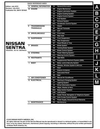
- 1. -1 QUICK REFERENCE INDEX A GENERAL INFORMATION GI General Information B ENGINE EM Engine Mechanical LU Engine Lubrication System CO Engine Cooling System EC Engine Control System FL Fuel System EX Exhaust System ACC Accelerator Control System C TRANSMISSION/ TRANSAXLE CL Clutch MT Manual Transaxle CVT CVT D DRIVELINE/AXLE FAX Front Axle RAX Rear Axle E SUSPENSION FSU Front Suspension RSU Rear Suspension WT Road Wheels & Tires F BRAKES BR Brake System PB Parking Brake System BRC Brake Control System G STEERING PS Power Steering System STC Steering Control System H RESTRAINTS SB Seat Belts SRS Supplemental Restraint System (SRS) I BODY BL Body, Lock & Security System GW Glasses, Window System & Mirrors RF Roof EI Exterior & Interior IP Instrument Panel SE Seat J AIR CONDITIONER MTC Manual Air Conditioner K ELECTRICAL SC Starting & Charging System LT Lighting System DI Driver Information System WW Wiper, Washer & Horn BCS Body Control System LAN LAN System AV Audio Visual, Navigation & Telephone System ACS Auto Cruise Control System PG Power Supply, Ground & Circuit Elements L MAINTENANCE MA Maintenance Edition: July 2010 Revision: July 2010 Publication No. SM1E-1B16U0 B D © 2010 NISSAN NORTH AMERICA, INC. All rights reserved. No part of this Service Manual may be reproduced or stored in a retrieval system, or transmitted in any form, or by any means, electronic, mechanical, photo-copying, recording or otherwise, without the prior written permission of Nissan North America, Inc. A C E F G H I J K L M
- 2. -2 This manual contains maintenance and repair procedures for the 2011 NISSAN SENTRA. In order to assure your safety and the efficient functioning of the vehicle, this manual should be read thoroughly. It is especially important that the PRECAUTIONS in the GI section be completely understood before starting any repair task. All information in this manual is based on the latest product information at the time of publication. The right is reserved to make changes in specifi- cations and methods at any time without notice. IMPORTANT SAFETY NOTICE The proper performance of service is essential for both the safety of the technician and the efficient functioning of the vehicle. The service methods in this Service Manual are described in such a manner that the service may be performed safely and accurately. Service varies with the procedures used, the skills of the technician and the tools and parts available. Accordingly, anyone using service procedures, tools or parts which are not specifically recommended by NISSAN must first be completely satisfied that neither personal safety nor the vehicle’s safety will be jeopardized by the service method selected.
- 3. 2011 QUICK REFERENCE INDEX: SENTRA QUICK REFERENCE INDEX: SENTRA Engine Tune-up Data: MR20DE INFOID:0000000006708607 GENERAL SPECIFICATIONS DRIVE BELT SPARK PLUG Unit: mm (in) *: Always check with the Parts Department for the latest parts information Engine Tune-up Data: QR25DE INFOID:0000000006708606 GENERAL SPECIFICATIONS Engine type MR20DE Cylinder arrangement In-line 4 Displacement cm3 (cu in) 1,997 (121.86) Bore and stroke mm (in) 84.0 x 90.1 (3.307 x 3.547) Valve arrangement DOHC Firing order 1-3-4-2 Number of piston rings Compression 2 Oil 1 Compression ratio 10.2 Compression pressure kPa (bar, kg/cm2 , psi) / 250 rpm Standard 1,390 (13.9, 14.2, 202) Minimum 1,140 (11.4. 11.6, 165) Differential limit between cylinders 100 (1.0, 1.0, 15) Tension of drive belt Auto adjustment by auto-tensioner Application Except for California For California Make NGK Denso Standard type* PLZKAR6A-11 FXE20HR-11 Spark plug gap Nominal: 1.1 (0.043) Model SE-R SE-R Spec V Cylinder arrangement In-line 4 Displacement cm3 (in3 ) 2,488 (151.82) Bore and stroke mm (in) 89.0 x 100 (3.50 x 3.94) Valve arrangement DOHC Firing order 1-3-4-2 Number of piston rings Compression 2 Oil 1 Compression ratio 9.5:1 10.5:1
- 4. QUICK REFERENCE INDEX: SENTRA 2011 DRIVE BELTS SPARK PLUG Unit: mm (in) *: Always check with the Parts Department for the latest parts information Front Wheel Alignment (Unladen*) INFOID:0000000006708605 Compression pressure kPa (kg/cm2, psi) / 250 rpm Standard 1,250 (12.8, 181.3) Minimum 1,060 (10.8, 153.7) Differential limit be- tween cylinders 100 (1.0, 14) Valve timing Unit: degree a b c d e f 224° 244° 0° 64° 3° 41° PBIC0187E Tension of drive belts Auto adjustment by auto tensioner Make NGK Type* Standard DILKAR6A-11 Gap (nominal) 1.1 (0.043) Engine MR20DE QR25DE QR25DE Model 2.0, 2.0 S, 2.0 SR, 2.0 SL SE-R SE-R SPEC-V Camber Degree minute (Decimal degree) LH Minimum -0° 37′ (-0.62°) -0° 42′ (-0.70°) Nominal -0° 10′ (-0.17°) -0° 15′ (-0.25°) Maximum 0° 29′ (0.48°) 0° 24′ (0.40°) RH Minimum -0° 49′ (-0.82°) -0° 54′ (-0.90°) Nominal -0° 10′ (-0.17°) -0° 15′ (-0.25°) Maximum 0° 17′ (0.28°) 0° 12′ (0.20°) LH - RH Minimum -0° 22′ (-0.37°) -0° 22′ (-0.37°) Nominal 0° 0′ (0.0°) 0° 0′ (0.0°) Maximum 0° 46′ (0.77°) 0° 46′ (0.77°)
- 5. 2011 QUICK REFERENCE INDEX: SENTRA *: Fuel, engine coolant and engine oil full. Spare tire, jack, hand tools and mats in designated positions. Rear Wheel Alignment (Unladen*) INFOID:0000000006708603 Caster Degree minute (Decimal degree) LH Minimum 4° 15′ (4.25°) 4° 30′ (4.50°) Nominal 4° 48′ (4.80°) 5° 3′ (5.05°) Maximum 5° 21′ (5.35°) 5° 36′ (5.60°) RH Minimum 4° 29′ (4.48°) 4° 44′ (4.73°) Nominal 5° 02′ (5.03°) 5° 17′ (5.28°) Maximum 5° 35′ (5.58°) 5° 50′ (5.83°) LH - RH Minimum -0° 48′ (-0.80°) -0°48′(-0.80°) Nominal -0° 14′ (-0.23°) -0° 14′ (-0.23°) Maximum 0° 20′ (0.33°) 0° 20′ (0.33°) Kingpin inclination Degree minute (Decimal degree) LH 10° 58′ (10.97°) 11° 13′ (11.22°) RH 11° 12′ (11.20°) 11° 27′ (11.45°) Toe-in Distance (A - B) Minimum -1.0 mm (-0.04 in) -1 mm (-0.04 in) Nominal 0.0 mm (0.00 in) 0 mm (0.00 in) Maximum 1.0 mm (0.04 in) 1 mm (0.04 in) Angle (left or right, each side) Degree minute (Degree) Minimum -0° 2′ 42" (-0.05°) -0° 2′ 42" (-0.05°) Nominal 0° 0′ 0" (0.00°) 0° 00′ (0.00°) Maximum 0° 2’ 42" (0.05°) 0° 2′ 42" (0.05°) SFA234AC Model 2.0, 2.0 S, 2.0 SR, 2.0 SL SE-R SE-R SPEC-V Camber Degree minute (Deci- mal degree) Minimum – 2° 00′ (– 2.00°) – 2° 00′ (– 2.00°) – 2° 00′ (– 2.00°) Nominal – 1° 30′ (– 1.50°) – 1° 30′ (– 1.50°) – 1° 30′ (– 1.50°) Maximum – 1° 00′ (– 1.00°) – 1° 00′ (– 1.00°) – 1° 00′ (– 1.00°) SEIA0363E
- 6. QUICK REFERENCE INDEX: SENTRA 2011 *: Fuel, engine coolant and engine oil full. Spare tire, jack, hand tools and mats in designated positions. Wheelarch Height (Unladen*) INFOID:0000000006708604 *: Fuel, radiator coolant and engine oil full. Spare tire, jack, hand tools and mats in designated positions. Brake Specifications INFOID:0000000006708601 Unit: mm (in) Toe-in Distance (A - B) Minimum – 3.0 mm ( – 0.118 in) – 2.0 mm ( – 0.079 in) – 1.0 mm (– 0.039 in) Nominal 1.0 mm (0.039 in) 2.0 mm (0.079 in) 3.0 mm (0.118 in) Maximum 5.0 mm (0.197 in) 6.0 mm (0.236 in) 7.0 mm (0.276 in) Angle left side or right side Degree minute (Decimal de- gree) Minimum – 0° 8′ 30" (– 0.14°) – 0° 5′ 30" (– 0.09°) – 0° 3′ 0" (– 0.05°) Nominal 0° 3′ 0" (0.05°) 0° 5′ 30" (0.09°) 0° 8′ 30" (0.14°) Maximum 0° 14′ 0" (0.23°) 0° 17′ 0" (0.28°) 0° 19′ 0" (0.32°) Engine MR20DE QR25DE Tire Size P205/60HR15 P205/55HR16 P225/45VR17 P225/45WR17 Front (Hf) mm (in) 689 (27.13) 692 (27.24) 690 (27.17) 679 (26.73) Rear (Hr) mm (in) 688 (27.09) 692 (27.24) 690 (27.17) 677 (26.65) LEIA0085E Applied model MR20DE QR25DE Base, S, SR, SL SE-R SE-R SPEC-V Front disc brake Brake model CLZ25VB CLZ25VJ AD25V Cylinder bore diameter 57.2 (2.252) 57.2 (2.252) 57.15 (2.250) Pad thickness 11 (0.433) 11 (0.433) 11 (0.433) Rotor outer diameter × thickness 280 × 24.0 (11.02 × 0.945) 296 × 26.0 (11.65 × 1.024) 320 × 28.0 (12.60 × 1.102) Rear disc brake Brake model — AD9A/DS17 Cylinder bore diameter — 34.93 (1.375) Pad thickness — 8.5 (0.335) Rotor outer diameter × thickness — 292 × 9.0 (11.50 × 0.354) Rear drum brake Brake model LT23E — — Cylinder bore diameter 19.05 (0.750) — — Lining Length × width × thickness 194.1 × 35 × 2.9 (7.642 × 1.378 × 0.114) — — Drum inner diameter 228.6 (9.000) — — Master cylinder Cylinder bore diameter 23.81 (0.937)
- 7. 2011 QUICK REFERENCE INDEX: SENTRA Brake Pedal INFOID:0000000006708602 Unit: mm (in) Front Disc Brake INFOID:0000000006708598 CLZ25VB Unit: mm (in) CLZ25VJ Unit: mm (in) Brake booster Booster model C255 Diaphragm diameter 255 (10.04) Recommended brake fluid DOT 3 Brake pedal height (H) (from dash lower panel top surface) 164.0 - 174.0 (6.46 - 6.85) Brake pedal full stroke (S) 135.1 (5.32) Clearance between pedal stopper bracket and threaded end of the stop lamp switch (C1) and ASCD cancel switch (C2), if equipped. 0.74 - 1.96 (0.0291 - 0.0772) AWFIA0557ZZ Brake pad Standard thickness (new) 11 (0.433) Repair limit thickness 2.0 (0.079) Disc rotor Standard thickness (new) 24.0 (0.945) Repair limit thickness 22.0 (0.866) Runout limit 0.035 (0.0014) Maximum uneven wear (mea- sured at 8 positions) 0.02 (0.0008) or less Brake pad Standard thickness (new) 11 (0.433) Repair limit thickness 2.0 (0.079)
- 8. QUICK REFERENCE INDEX: SENTRA 2011 AD25V Unit: mm (in) Rear Disc Brake INFOID:0000000006708599 AD9A/DS17 Unit: mm (in) Rear Drum Brake INFOID:0000000006708600 LT23E Unit: mm (in) Fluids and Lubricants: MR20DE INFOID:0000000006708596 Disc rotor Standard thickness (new) 26.0 (1.024) Repair limit thickness 24.0 (0.945) Runout limit 0.035 (0.0014) Maximum uneven wear (mea- sured at 8 positions) 0.02 (0.0008) or less Brake pad Standard thickness (new) 11 (0.433) Repair limit thickness 2.0 (0.079) Disc rotor Standard thickness (new) 28.0 (1.102) Repair limit thickness 26.0 (1.024) Runout limit 0.035 (0.0014) Maximum uneven wear (mea- sured at 8 positions) 0.02 (0.0008) or less Brake pad Standard thickness (new) 8.5 (0.335) Repair limit thickness 2.0 (0.079) Disc rotor Standard thickness (new) 9.0 (0.354) Repair limit thickness 8.0 (0.315) Runout limit 0.07 (0.0028) Maximum uneven wear (mea- sured at 8 positions) 0.015 (0.0006) or less Brake lining Standard thickness (new) 2.9 (0.114) Repair limit thickness 1.5 (0.059) Drum Standard inner diameter (new) 228.6 (9.000) Repair limit inner diameter 230.0 (9.055) Description Capacity (Approximate) Liter US measure Imp measure Fuel 55.0 14 1/2 gal 12 1/8 gal Engine oil Drain and refill With oil filter change 3.9 4 1/8 qt 3 3/8 qt Without oil filter change 3.6 3 7/8 qt 3 1/8 qt Dry engine (engine overhaul) 4.4 4 5/8 qt 3 7/8 qt Cooling system (with reservoir at MAX level) 7.0 7 3/8 qt 6 1/8 qt Manual transaxle fluid (MTF) 2.0 4 1/4 pt 3 1/2 pt CVT fluid 7.3 7 3/4 qt 6 3/8 qt Brake and clutch fluid — — — Multi-purpose grease — — —
- 9. 2011 QUICK REFERENCE INDEX: SENTRA Fluids and Lubricants: QR25DE INFOID:0000000006708597 Windshield washer fluid 3.5 3 3/4 qt 3 1/8 qt Air conditioning system refrigerant 0.50 ± 0.025 kg 1.10 ± 0.055 lb 1.10 ± 0.055 lb Air conditioning system oil 150 m 5.03 fl oz 5.3 fl oz Description Capacity (Approximate) Liter US measure Imp measure Fuel 55.0 14 1/2 gal 12 1/8 gal Description Capacity (Approximate) Liter US measure Imp measure Fuel 55.0 14 1/2 gal 12 1/8 gal Engine oil Drain and refill With oil filter change 4.3 4 1/2 qt 3 3/4 qt Without oil filter change 4.0 4 1/4 qt 3 1/2 qt Dry engine (engine overhaul) 5.1 5 3/8 qt 4 1/2 qt Cooling system (with reservoir at MAX level) M/T models 6.9 7 1/4 qt 6 1/8 qt CVT models 7.1 7 1/2 qt 6 1/4 qt Manual transaxle fluid (MTF) 1.7 3 5/8 pt 3 pt CVT fluid 7.5 7 7/8 qt 6 5/8 qt Brake and clutch fluids — — — Multi-purpose grease — — — Windshield washer fluid 3.5 3 3/4 qt 3 1/8 qt Air conditioning system refrigerant 0.50 ± 0.025 kg 1.10 ± 0.055 lb 1.10 ± 0.055 lb Air conditioning system oil 150 m 5.03 fl oz 5.3 fl oz
- 10. GI-1 GENERAL INFORMATION C D E F G H I J K L M B GI SECTION GI N O P CONTENTS GENERAL INFORMATION SERVICE INFORMATION ........................ .... 2 PRECAUTIONS .............................................. ..... 2 Description .......................................................... ......2 Precaution for Supplemental Restraint System (SRS) "AIR BAG" and "SEAT BELT PRE-TEN- SIONER" ............................................................. ......2 Precaution Necessary for Steering Wheel Rota- tion After Battery Disconnect ............................... ......2 General Precaution ............................................. ......3 Precaution for Three Way Catalyst ..................... ......4 Precaution for Fuel (Unleaded Regular Gasoline Recommended) MR20DE and QR25DE Except SE-R Spec-V ....................................................... ......4 Precaution for Fuel (Unleaded Premium Gasoline Required) QR25DE SE-R Spec-V Only .............. ......5 Precaution for Multiport Fuel Injection System or Engine Control System ....................................... ......5 Precaution for Hoses ........................................... ......5 Precaution for Engine Oils .................................. ......6 Precaution for Air Conditioning ........................... ......7 HOW TO USE THIS MANUAL ....................... ..... 8 Description .......................................................... ......8 Terms .................................................................. ......8 Units .................................................................... ......8 Contents .............................................................. ......8 Relation between Illustrations and Descriptions . ......9 Component .......................................................... ......9 How to Follow Trouble Diagnosis ........................ ....10 How to Read Wiring Diagram .............................. ....14 Abbreviations ...................................................... ....21 SERVICE INFORMATION FOR ELECTRICAL INCIDENT ....................................................... ....23 How to Check Terminal ....................................... ....23 How to Perform Efficient Diagnosis for an Electri- cal Incident .......................................................... ....26 Control Units and Electrical Parts ........................ ....33 CONSULT-III CHECKING SYSTEM .................36 Description ........................................................... ....36 Function and System Application ........................ ....36 CONSULT-III Data Link Connector (DLC) Circuit....37 LIFTING POINT .................................................39 Special Service Tool ............................................ ....39 Garage Jack and Safety Stand and 2-Pole Lift ... ....39 Board-On Lift ....................................................... ....40 TOW TRUCK TOWING .....................................41 Tow Truck Towing ............................................... ....41 Vehicle Recovery (Freeing a Stuck Vehicle) ....... ....41 TIGHTENING TORQUE OF STANDARD BOLTS ...............................................................43 Tightening Torque Table ..................................... ....43 RECOMMENDED CHEMICAL PRODUCTS AND SEALANTS ...............................................44 Recommended Chemical Product and Sealant ... ....44 IDENTIFICATION INFORMATION ....................45 Model Variation .................................................... ....45 Dimensions .......................................................... ....48 Wheels & Tires .................................................... ....48 TERMINOLOGY ................................................49 SAE J1930 Terminology List ............................... ....49 Revision: July 2010 2011 Sentra
- 11. Thank you very much for your reading. Please Click Here Then Get More Information. NOTE: If there is no response to click on the link above, please download the PDF document first and then click on it.
- 12. GI-2 < SERVICE INFORMATION > PRECAUTIONS SERVICE INFORMATION PRECAUTIONS Description INFOID:0000000006150940 Observe the following precautions to ensure safe and proper servicing. These precautions are not described in each individual section. Precaution for Supplemental Restraint System (SRS) "AIR BAG" and "SEAT BELT PRE-TENSIONER" INFOID:0000000006417975 The Supplemental Restraint System such as “AIR BAG” and “SEAT BELT PRE-TENSIONER”, used along with a front seat belt, helps to reduce the risk or severity of injury to the driver and front passenger for certain types of collision. This system includes seat belt switch inputs and dual stage front air bag modules. The SRS system uses the seat belt switches to determine the front air bag deployment, and may only deploy one front air bag, depending on the severity of a collision and whether the front occupants are belted or unbelted. Information necessary to service the system safely is included in the SRS and SB section of this Service Man- ual. WARNING: • To avoid rendering the SRS inoperative, which could increase the risk of personal injury or death in the event of a collision which would result in air bag inflation, all maintenance must be performed by an authorized NISSAN/INFINITI dealer. • Improper maintenance, including incorrect removal and installation of the SRS can lead to personal injury caused by unintentional activation of the system. For removal of Spiral Cable and Air Bag Module, see the SRS section. • Do not use electrical test equipment on any circuit related to the SRS unless instructed to in this Service Manual. SRS wiring harnesses can be identified by yellow and/or orange harnesses or har- ness connectors. PRECAUTIONS WHEN USING POWER TOOLS (AIR OR ELECTRIC) AND HAMMERS WARNING: • When working near the Airbag Diagnosis Sensor Unit or other Airbag System sensors with the Igni- tion ON or engine running, DO NOT use air or electric power tools or strike near the sensor(s) with a hammer. Heavy vibration could activate the sensor(s) and deploy the air bag(s), possibly causing serious injury. • When using air or electric power tools or hammers, always switch the Ignition OFF, disconnect the battery, and wait at least 3 minutes before performing any service. Precaution Necessary for Steering Wheel Rotation After Battery Disconnect INFOID:0000000006150942 NOTE: • This Procedure is applied only to models with Intelligent Key system and NATS (NISSAN ANTI-THEFT SYS- TEM). • Remove and install all control units after disconnecting both battery cables with the ignition knob in the ″LOCK″ position. • Always use CONSULT-III to perform self-diagnosis as a part of each function inspection after finishing work. If DTC is detected, perform trouble diagnosis according to self-diagnostic results. For models equipped with the Intelligent Key system and NATS, an electrically controlled steering lock mech- anism is adopted on the key cylinder. For this reason, if the battery is disconnected or if the battery is discharged, the steering wheel will lock and steering wheel rotation will become impossible. If steering wheel rotation is required when battery power is interrupted, follow the procedure below before starting the repair operation. OPERATION PROCEDURE 1. Connect both battery cables. NOTE: Supply power using jumper cables if battery is discharged. Revision: July 2010 2011 Sentra
- 13. PRECAUTIONS GI-3 < SERVICE INFORMATION > C D E F G H I J K L M B GI N O P 2. Use the Intelligent Key or mechanical key to turn the ignition switch to the ″ACC″ position. At this time, the steering lock will be released. 3. Disconnect both battery cables. The steering lock will remain released and the steering wheel can be rotated. 4. Perform the necessary repair operation. 5. When the repair work is completed, return the ignition switch to the ″LOCK″ position before connecting the battery cables. (At this time, the steering lock mechanism will engage.) 6. Perform a self-diagnosis check of all control units using CONSULT-III. General Precaution INFOID:0000000006150943 • Do not operate the engine for an extended period of time without proper exhaust ventilation. Keep the work area well ventilated and free of any flammable materials. Special care should be taken when handling any flam- mable or poisonous materials, such as gasoline, refrigerant gas, etc. When working in a pit or other enclosed area, be sure to prop- erly ventilate the area before working with hazardous materials. Do not smoke while working on the vehicle. • Before jacking up the vehicle, apply wheel chocks or other tire blocks to the wheels to prevent the vehicle from moving. After jack- ing up the vehicle, support the vehicle weight with safety stands at the points designated for proper lifting before working on the vehi- cle. These operations should be done on a level surface. • When removing a heavy component such as the engine or tran- saxle/transmission, be careful not to lose your balance and drop them. Also, do not allow them to strike adjacent parts, especially the brake tubes and master cylinder. • Before starting repairs which do not require battery power: Turn off ignition switch. Disconnect the negative battery terminal. • If the battery terminals are disconnected, recorded memory of radio and each control unit is erased. • Battery posts, terminals and related accessories contain lead and lead compounds. Wash hands after handling. • To prevent serious burns: Avoid contact with hot metal parts. Do not remove the radiator cap when the engine is hot. • Dispose of or recycle drained oil or the solvent used for cleaning parts in an appropriate manner. • Do not attempt to top off the fuel tank after the fuel pump nozzle shuts off automatically. Continued refueling may cause fuel overflow, resulting in fuel spray and possibly a fire. • Clean all disassembled parts in the designated liquid or solvent prior to inspection or assembly. SGI285 SGI231 SEF289H SGI233 Revision: July 2010 2011 Sentra
- 14. GI-4 < SERVICE INFORMATION > PRECAUTIONS • Replace oil seals, gaskets, packings, O-rings, locking washers, cotter pins, self-locking nuts, etc. with new ones. • Replace inner and outer races of tapered roller bearings and needle bearings as a set. • Arrange the disassembled parts in accordance with their assembled locations and sequence. • Do not touch the terminals of electrical components which use microcomputers (such as ECM). Static electricity may damage internal electronic components. • After disconnecting vacuum or air hoses, attach a tag to indicate the proper connection. • Use only the fluids and lubricants specified in this manual. • Use approved bonding agent, sealants or their equivalents when required. • Use hand tools, power tools (disassembly only) and recommended special tools where specified for safe and efficient service repairs. • When repairing the fuel, oil, water, vacuum or exhaust systems, check all affected lines for leaks. • Before servicing the vehicle: Protect fenders, upholstery and carpeting with appropriate covers. Take caution that keys, buckles or buttons do not scratch paint. WARNING: To prevent ECM from storing the diagnostic trouble codes, do not carelessly disconnect the harness connectors which are related to the engine control system and TCM (transmission control module) system. The connectors should be disconnected only when working according to the WORK FLOW of TROUBLE DIAGNOSES in EC and CVT sections. Precaution for Three Way Catalyst INFOID:0000000006150944 If a large amount of unburned fuel flows into the catalyst, the catalyst temperature will be excessively high. To prevent this, follow the instructions. • Use unleaded gasoline only. Leaded gasoline will seriously damage the three way catalyst. • When checking for ignition spark or measuring engine compression, make tests quickly and only when nec- essary. • Do not run engine when the fuel tank level is low, otherwise the engine may misfire, causing damage to the catalyst. Do not place the vehicle on flammable material. Keep flammable material off the exhaust pipe and the three way catalyst. Precaution for Fuel (Unleaded Regular Gasoline Recommended) MR20DE and QR25DE Except SE-R Spec-V INFOID:0000000006150945 Use unleaded regular gasoline with an octane rating of at least 87 AKI (Anti-Knock Index) number (research octane number 91). E-85 fuel (85% fuel ethanol, 15% unleaded gasoline) may only be used in vehicles specif- ically designed for E-85 fuel (i.e. Flexible Fuel Vehicle - FFV models). CAUTION: Do not use leaded gasoline. Using leaded gasoline will damage the three way catalyst. Using a fuel other than that specified could adversely affect the emission control devices and systems, and could PBIC0190E SGI234 Revision: July 2010 2011 Sentra
- 15. PRECAUTIONS GI-5 < SERVICE INFORMATION > C D E F G H I J K L M B GI N O P also affect the warranty coverage validity. Do not use E-85 fuel (85% fuel ethanol, 15% unleaded gaso- line) unless the vehicle is specifically designed for E-85 fuel (i.e. Flexible Fuel Vehicle - FFV models). Precaution for Fuel (Unleaded Premium Gasoline Required) QR25DE SE-R Spec-V Only INFOID:0000000006150946 Use unleaded premium gasoline with an octane rating of at least 91 AKI (Anti-Knock Index) number (Research octane number 96). If unleaded premium gasoline is not available, unleaded regular gasoline with an octane rating of at least 87 AKI number (Research octane number 91) can be used, but only under the following precautions: • have the fuel tank filled only partially with unleaded regular gasoline, and fill up with unleaded premium gas- oline as soon as possible. • avoid full throttle driving and abrupt acceleration. However, for maximum vehicle performance, the use of unleaded premium gasoline is recommended. CAUTION: Do not use leaded gasoline. Using leaded gasoline will damage the three way catalyst. Do not use E-85 fuel (85% fuel ethanol, 15% unleaded gasoline) unless the vehicle is specifically designed for E-85 fuel (i.e. Flexible Fuel Vehicle - FFV models). Using a fuel other than that specified could adversely affect the emission control devices and systems, and could also affect the warranty coverage validity. Precaution for Multiport Fuel Injection System or Engine Control System INFOID:0000000006150947 • Before connecting or disconnecting any harness connector for the multiport fuel injection system or ECM: Turn ignition switch to “OFF” position. Disconnect negative battery terminal. Otherwise, there may be damage to ECM. • Before disconnecting pressurized fuel line from fuel pump to injec- tors, be sure to release fuel pressure. • Be careful not to jar components such as ECM and mass air flow sensor. Precaution for Hoses INFOID:0000000006150948 HOSE REMOVAL AND INSTALLATION • To prevent damage to rubber hose, do not pry off rubber hose with tapered tool or screwdriver. SGI787 SMA019D Revision: July 2010 2011 Sentra