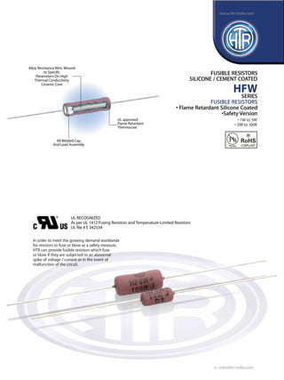
1. All Welded Cap
And Lead Assembly
UL RECOGNIZED
As per UL 1412 Fusing Resistors and Temperature-Limited Resistors
UL file # E 342534
Alloy Resistance Wire, Wound
to Specific
Parameters On High
Thermal Conductivity
Ceramic Core
UL approved
Flame Retardant
Thermocoat
FUSIBLE RESISTORS
SILICONE / CEMENT COATED
HFW
SERIES
FUSIBLE RESISTORS
• Flame Retardant Silicone Coated
•Safety Version
In order to meet the growing demand worldwide
for resistors to fuse or blow as a safety measure,
HTR can provide fusible resistors which fuse
or blow if they are subjected to an abnormal
spike of voltage / current or in the event of
malfunction of the circuit.
• 1W to 5W
• 10R to 100R
e : info@htr-india.com
www.htr-india.com
Rev Date : 22/11/2016
Asper AEC-Q200
2. PHYSICAL CONFIGURATION
HTR
TYPE
POWER
RATING
at 40°C
(Ambient)
*
L
(max)
D
(max)
DIMENSIONS (mm) RESISTANCE
RANGE
TYPICAL
WEIGHT
PER PC
(gms)
min max
l
±1.5
d
±0.05
Power Rating (Rated Ambient Temperature) Full Power dissipation at 40°C and linearly derated
to zero at +350°C - Refer Derating Curve above
Resistance Tolerances Available ±10% (K); ±5% (J); ±3% (H); ±2%(G); ±1% (F)
Temperature Range -55°C to +350°C with suitable derating as per derating curve.
Voltage Rating / Limiting Voltage / Max. Working Voltage V= PxR
Dielectric Withstanding Voltage / Voltage Proof ∆R ± (1% + R05) - No flashover, mechanical
(based on limiting voltage x 2 for 60 secs) damage, arcing or insulation breakdown
Short Time Overload (5 x Rated Power for 5 secs) ∆R ± (2% + R05)
Temperature Co-efficient of Resistance ±60 ppm /°C for <10R - Average
± 90 ppm /°C or ± 30 ppm /°C for >10R depending on wire selected
Insulation Resistance >1000MΩ (Min)
Temperature Cycling ∆R ± [2% + R05]
(Room temperature →-55°C → Room Temperature→
200°C → Room Temperature for 5 cycles)
Damp Heat (Steady State) ∆R ± [≤5% + R05] - Average
(40°C at 93% R.H for 1000 hours - no load applicable)
Endurance - Load Life ∆R ± [≤5% + R05 ] - Average
(70°C with limiting voltage - 1.5 hours on /
0.5 hours off for 1000 hours)
Solvent Resistance No effect on coating / marking
(IPA for 60 secs ±10 secs )
PARAMETER/PERFORMANCE TEST & TEST METHOD PERFORMANCE REQUIREMENTS
* Coating overflow on each lead not to exceed half of‘D’.
• Resistance values below the minimum range can be supplied on request.
+ Certified to UL 1412
ELECTRICAL AND ENVIRONMENTAL
CHARACTERISTICS / DATA
F1W* 1W 6.75 4.50 38 0.8 10R 100R 0.60
HF1W* 1W 9.5 4.5 38 0.8 10R 100R 0.7
HF2W*+
2W 9.2 3.6 38 0.8 10R 100R 0.55
F2W* 2W 11.5 4.5 38 0.8 10R 100R 0.75
DF2W* 2W (700
C) 14.5 6.0 38 0.8 10R 100R 1.2
HF3W*+
3W 11.5 5.5 38 0.8 10R 100R 1.1
F3W* 3W 15.5 6.0 38 0.8 10R 100R 1.4
HF4W*+
4W 16.0 6.0 38 0.8 10R 100R 1.4
HF5W*+
5W 16.8 7.5 38 0.8 10R 100R 1.8
F5W* 5W 15.7 5.9 38 0.8 10R 100R 1.35
FUSIBLE
RESISTORS
SILICONE /
CEMENT
COATED
HFW
e : info@htr-india.com
www.htr-india.com
Rev Date : 22/11/2016
3. MECHANICAL SPECIFICATIONS
Terminal Tensile Strength 50 Newtons
Resistance To Soldering Heat (260°C - 270°C for 10 secs) ∆R ± [0.5% + R05] - Typical
Solderability (As per IEC pub. 60068 - 2 - 20 Ta) Must meet the requirements laid down
Marking As per IEC Pub. 60062
PARAMETER/PERFORMANCE TEST & TEST METHOD PERFORMANCE REQUIREMENTS
As mentioned previously, a fusible resistor is a tailormade dual purpose component –
a. In normal conditions it functions as a resistor.
b. In high overload / fault conditions it acts as a fuse / safety device.
TYPICAL APPLICATIONS
Note : Contrary to popular belief, fusible resistors are not standard resistor types and each type of fusible resistor must be tailor designed
to suit a particular application.
FUSIBLE
RESISTORS
SILICONE /
CEMENT
COATED
HFW
FOR EXAMPLE
1. For Tape & Ammo packing - HF2W*T
2. For Tape & Reel - HF2W*TR
ORDERING INFORMATION
Series Type Packing Resistance Value Tolerance
HFW HF2W* Bulk HF2W* 15R K
Tape & Ammo HF2W*T
Tape & Reel HF2W*TR
ORDERING INFORMATION
THE HFW SERIES OF RESISTORS IS A SPECIAL“SAFETY VERSION”AVAILABLE IN RESISTANCE VALUES ≥10R
WHERE THE RESISTOR WILL FUSE INSTANTANEOUSLY WHEN MAINS VOLTAGE 110V / 120V IS APPLIED WITH NO FLAME OR EXPLOSION.
For resistance values <10R the fusing timing and suitability must be tested for each individual application.
Precautions to be taken : Before conducting this test, the voltage must be correctly set / adjusted by first using a dummy piece which
should then be discarded.
NOTE: THE CUSTOMER IS STRONGLY ADVISED TO ASCERTAIN THE SUITABILITY OF THE RESISTOR FOR HIS
PARTICULAR APPLICATION BEFORE ORDERING IN BULK.
e : info@htr-india.com
www.htr-india.com
Rev Date : 22/11/2016
![PHYSICAL CONFIGURATION
HTR
TYPE
POWER
RATING
at 40°C
(Ambient)
*
L
(max)
D
(max)
DIMENSIONS (mm) RESISTANCE
RANGE
TYPICAL
WEIGHT
PER PC
(gms)
min max
l
±1.5
d
±0.05
Power Rating (Rated Ambient Temperature) Full Power dissipation at 40°C and linearly derated
to zero at +350°C - Refer Derating Curve above
Resistance Tolerances Available ±10% (K); ±5% (J); ±3% (H); ±2%(G); ±1% (F)
Temperature Range -55°C to +350°C with suitable derating as per derating curve.
Voltage Rating / Limiting Voltage / Max. Working Voltage V= PxR
Dielectric Withstanding Voltage / Voltage Proof ∆R ± (1% + R05) - No flashover, mechanical
(based on limiting voltage x 2 for 60 secs) damage, arcing or insulation breakdown
Short Time Overload (5 x Rated Power for 5 secs) ∆R ± (2% + R05)
Temperature Co-efficient of Resistance ±60 ppm /°C for <10R - Average
± 90 ppm /°C or ± 30 ppm /°C for >10R depending on wire selected
Insulation Resistance >1000MΩ (Min)
Temperature Cycling ∆R ± [2% + R05]
(Room temperature →-55°C → Room Temperature→
200°C → Room Temperature for 5 cycles)
Damp Heat (Steady State) ∆R ± [≤5% + R05] - Average
(40°C at 93% R.H for 1000 hours - no load applicable)
Endurance - Load Life ∆R ± [≤5% + R05 ] - Average
(70°C with limiting voltage - 1.5 hours on /
0.5 hours off for 1000 hours)
Solvent Resistance No effect on coating / marking
(IPA for 60 secs ±10 secs )
PARAMETER/PERFORMANCE TEST & TEST METHOD PERFORMANCE REQUIREMENTS
* Coating overflow on each lead not to exceed half of‘D’.
• Resistance values below the minimum range can be supplied on request.
+ Certified to UL 1412
ELECTRICAL AND ENVIRONMENTAL
CHARACTERISTICS / DATA
F1W* 1W 6.75 4.50 38 0.8 10R 100R 0.60
HF1W* 1W 9.5 4.5 38 0.8 10R 100R 0.7
HF2W*+
2W 9.2 3.6 38 0.8 10R 100R 0.55
F2W* 2W 11.5 4.5 38 0.8 10R 100R 0.75
DF2W* 2W (700
C) 14.5 6.0 38 0.8 10R 100R 1.2
HF3W*+
3W 11.5 5.5 38 0.8 10R 100R 1.1
F3W* 3W 15.5 6.0 38 0.8 10R 100R 1.4
HF4W*+
4W 16.0 6.0 38 0.8 10R 100R 1.4
HF5W*+
5W 16.8 7.5 38 0.8 10R 100R 1.8
F5W* 5W 15.7 5.9 38 0.8 10R 100R 1.35
FUSIBLE
RESISTORS
SILICONE /
CEMENT
COATED
HFW
e : info@htr-india.com
www.htr-india.com
Rev Date : 22/11/2016](data:image/gif;base64,R0lGODlhAQABAIAAAAAAAP///yH5BAEAAAAALAAAAAABAAEAAAIBRAA7)