GWC Valve International Pressure Seal Valves
•
0 likes•1,309 views

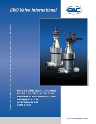
GWC produces a wide variety of Cast Steel Pressure Seal Gate, Globe and Check valves. Other available pressure seal designs include Tilting Disc, Piston Type and Stop Check valves.

Recommended
Recommended
More Related Content
What's hot
What's hot (20)
Similar to GWC Valve International Pressure Seal Valves
Similar to GWC Valve International Pressure Seal Valves (20)
More from GWC Valve International
Recently uploaded
Recently uploaded (20)
GWC Valve International Pressure Seal Valves
- 1. GWC Valve InternationalProventechnologyforindividualvalvesolutions–worldwide PRESSURE SEAL VALVES GATE, GLOBE & CHECK PRESSURE CLASS: ASME 600 - 2500 SIZE RANGE: 2” - 24” API STANDARD: 600 ASME B16.34 Catalog Number PS-1001
- 3. GWCValveInternational 3 TABLE OF CONTENTS Pressure Seal Gate Valves Class 600, 900, 1500 and 2500 8 Construction Specification 9 Standard Features 4 Ordering Guide 6 Motor Operated and Bevel Gear Operated Valves 7 Pressure Seal Globe Valves Class 600, 900, 1500 and 2500 10 Construction Specification 11 Pressure Seal Swing Check Valves Class 600, 900, 1500 and 2500 12 Construction Specification 13 Pressure-Temperature Ratings 14 Terms and Conditions of Sale 16 Return Goods Policy / Warranty 17
- 4. GWCValveInternational 4 Standard Features GWC pressure seal valves are intended for high pressure, high temperature application in all types of fluid except where serve coking is a factor. The design and material selections provide excellent service in nuclear steam generating stations, industrial and chemical plants and thermal power plants. Our pressure seal valves provide the most efficient flow passage and sealing features possible resulting in significant weight savings, ease of installation and maintenance features. Manufacturing and quality assurance procedures include extra controls on dimensional, nondestructive examination and testing of critical areas such as the gasket sealing, butt-weld ends, and stellite sealing surfaces. Design Construction Bonnet Type Type A GATE Class 600, 900, 1500 & 2500 Size 4” & smaller GLOBE Class 600, 900, 1500 Size 4” & smaller Class 2500 Size 3” & smaller Type B GATE Class 600, 900, 1500 & 2500 Size 6” & larger GLOBE Class 600, 900, 1500 Size 6” & larger Class 2500 Size 4” & large Type C SWING CHECK Class 600, 900 & 1500 Size 4” & smaller Class 2500 Size 3” & smaller Type D SWING CHECK Class 600, 900 & 1500 Size 6” & larger Class 2500 Size 4” & larger 2. Wedge (Gate Valve) The flexible wedge is a one piece, fully guided cast wedge with a central hub to allow the seating faces to move relative to each other thus compensating for distortion of the body seats due to thermal expansion or piping loads. Seat ring and wedge seating surface are set at a nine degree angle from vertical to minimize sliding contact of the wedge and seat ring during opening and closing. Wedging actions help effect a tight seal in low differential pressure services. Flexible wedge construction resists wedge sticking or binding in services where the valve may be closed when hot and opened when cold. Seating surfaces are stellited to provide high cycle capability. BODY: Flow areas are designed for minimum turbulence and pressure drop. BONNET: Ample stuffing box and stellited stem guide and back seat shoulder are provided for accurate guiding of the stem and back seat. Cast body and bonnet quality requirements are considered in design of GWC valves. 1. Body and Bonnet
- 5. GWCValveInternational 5 Standard Features 3. Disc (Globe & Swing Check Valve) Globe and check type discs are accurately fitted and guided to minimize vibration. Seating surfaces are stellited. 4. Hammer Blow Type Hand Wheel & Ball Bearing Type Yoke Sleeve Hammer Blow Type Hand Wheel All globe valves are equipped with hammer blow type hand wheel. Two integrally cast lugs on the upside of hand wheel simultaneously strike a steel crossbar which is connected directly to valve stem on smaller sizes or to the yoke sleeve on large sizes. Bearing lnsert Type Yoke Sleeve Large, high pressure valves can require a tremendous amount of torque to open and close the valve. Use of ball bearings in the yoke sleeve reduce the operating torque of these difficult-to- operate valves by as much as 50 percent. Class GATE GLOBE 600 Size 6” & Larger Size 6” & Larger900 Size 2”, 2-1/2”, 6” & Larger 1500 Size 2” & Larger 2500 Size 3” & Larger 5. Standard Pressure Seal Design The segmental thrust ring absorbs all the thrust applied by internal pressure. A hardened stainless steel protective ring prevents deformation of the top surface of the soft metallic gasket. The gasket can be removed freely without the sealing surface of the body damaging. 6. Packing Adjustment All gate and globe valves are provided with a two piece packing gland to minimize the possibility of scoring the stem if the gland is tightened unevenly. Eye bolt remains fastened to the bonnet. They swing out of the way to simplify packing replacement and are oriented so they can be adjusted from one side of the valve. 7. Deep Stuffing Boxes Deep stuffing boxes are standard on gate and globe valves. The design provides extra packing for a more reliable stem seal, or sufficient depth for packing with an optional lantern ring in the middle. When equipped with a lantern ring, a tapped and plugged hole is provided. When specified, it can be fitted with a ball grease injector.
- 6. GWCValveInternational 6 3. END CONNECTION 4. MATERIAL (Body + Bonnet/CAP) 5. MATERIAL (Trim) 1. MODEL 2. RATING 6. OPERATOR 7. SPECIAL REQUIREMENT Ordering Guide Example: 6˝ Figure #7907-I-5-GO 6” GATE VALVE, PRESSURE SEAL BONNET, BW ENDS, A217 WC6 BODY, WC6 DISC W/ STELLITE OVERLAY, F11 SEATS W/STELLITE OVERLAY, F6 STEM, GEAR OP 90 7 5 1. 2. 4. 5. 6. GOI7 3. 7 - API 600/ASME B16.34 PRESSURE SEAL BONNET GATE VALVE 8 - ASME B16.34 PRESSURE SEAL BONNET GLOBE VALVE 9 - ASME B16.34 PRESSURE SEAL BONNET SWING CHECK VALVE 12 - ASME B16.34 PRESSURE SEAL BONNET TILTING DISC CHECK VALVE 14 - ASME B16.34 PRESSURE SEAL BONNET PISTON CHECK VALVE 16 - ASME B16.34 PRESSURE SEAL BONNET STOP CHECK VALVE 60 - Class 600 90 - Class 900 150 - Class 1500 250 - Class 2500 0 - RF FLANGED 7 - BUTTWELD 9 - RING JOINT X - OTHER A - WCB B - WCC C - LCC D - LCB H - WC1 I - WC6 J - WC9 K - C5 L - C12 M - CF8 N - CF8M O - CF3 P - CF3M Q - CF8C R - CN7M S - A890 4A T - A890 5A U - A890 6A X - OTHER 1 - 13CR 8 - 13CR 1/2 STELLITE 5 - 13CR FULL STELLITE 2 - 304SS 2S - 304SS 1/2 STELLITE 15 - 304SS FULL STELLITE 10 - 316SS 12 - 316SS 1/2 STELLITE 16 - 316SS FULL STELLITE 9 - MONEL 11 - MONEL 1/2 STELLITE 13 - ALLOY 20 14 - ALLOY 20 1/2 STELLITE 17 - 347SS 17H - 347SS 1/2 STELLITE 17S - 347SS FULL STELLITE 21 - F51 22 - F53 23 - F55 O - OTHER - HANDWHEEL OPERATOR GO - BEVEL GEAR OPERATOR B - BARE STEM N - NACE MR-01-75 S - SUPPLY COMPLETE INFORMATION Y - “Y” PATTERN
- 7. GWCValveInternational 7 Motor Operated Valves All GWC valves can be equipped with electric, pneumatic motor operators. Customers are asked, when ordering, to specify the following requirements that may enable us to supply the correct size of operator. 1. Medium 2. Working temperature 3. Working pressure 4. Differential pressure across the valve 5. Nominal diameter of the valve 6. Type of actuator 7. Voltage and frequency, or air pressure 8. Closing time 9. The need for position indicators or position transmitter etc. 10. Number and type of any auxiliary contact required. 11. Special classes of insulation 12. Waterproof or explosion proof MOTOR OPERATED & BEVEL GEAR OPERATED VALVES GWC bevel gear, valve operators are directly mounted to the gate and globe valves which receive the thrust loads. This results in easy manual opening and closing of the valves. The unit is of compact design with integral thrust bearings. Characteristics 1. The unit is of fully enclosed construction, filled with high pressure grease and ready for immediate use. 2. The unit results in easy valve operation and has a hammer blow device. 3. The stem nut is driven by involute splines. The stem nut may be easily removed from the unit for machining the threads. 4. The stem cover and stem plug are all optional equipment. Bevel Gear Operated Valves
- 8. GWCValveInternational 8 Service Recommendation 1. Gate valves are normally used for on-off service. They are not recommended for throttling service. 2. Gate valves are normally installed in horizontal pipe runs with the valve stem vertically up. They can also be installed in vertical or horizontal pipe runs with the valve stem other than vertical, but special construction may be required depending on valve size, service, conditions, and material. When purchasing valves for other than the normal installation, valve orientation should be specified. 3. After closing a gate valve with sufficient force to develop shutoff, the stem should be backed off slightly (1/8 to 1/4 turn) to relieve stem load. This will enable the stem to expand slightly-without bending or damaging the valve and will not affect valve shutoff. GATE VALVES standard features Class 600 7607 Class 900 7907 Class 1500 71507 Class 2500 72507 Model Number No. PART NAME A216 WCB A217 WC6 A217 WC9 A217 C5 A351 CF8M 1 Body A216 WCB A217 WC6 A217 WC9 A217 C5 A351 CF8M 2 Bonnet A216 WCB A217 WC6 A217 WC9 A217 C5 A351 CF8M 3 Wedge A216 WCB + Stellite A216 WCB + Stellite A217 WC9 + Stellite A217 C5 + Stellite A351 CF8M + Stellite 4 Stem A182 F6 A182 F6 A182 F6 A182 F6 A182 F316 5 Hand Wheel A197 or WCB A197 or WCB A197 or WCB A197 or WCB A197 or WCB 6 Body Seat Ring A105 + Stellite A182 F11 + Stellite A182 F22 + Stellite A182 F5a + Stellite A182 F316 + Stellite 7 Gland Flange A283-D A283-D A283-D A283-D A283-D 8 Packing Gland C/S 1020 + Cr Plate C/S 1020 + Cr Plate C/S 1020 + Cr Plate C/S 1020 + Cr Plate A479-316 9 Yoke Sleeve A439-D2C A439-D2C A439-D2C A439-D2C A439-D2C 10 Yoke Cap C/S1020 C/S1020 C/S1020 C/S1020 C/S1020 + Cr Plate 11 Hand Wheel Nut C/S1020 C/S1020 C/S1020 C/S1020 C/S1020 + Cr Plate 12 Bonnet Clamp C/S 1045 C/S1045 C/S1045 C/S1045 A351 CF8M 13 Yoke A216 WCB A217 WC6 A217 WC9 A217 C5 A351 CF8M 14 Hinge Clamp A216 WCB A217 WC6 A217 WC9 A217 C5 A351 CF8M 15 Gasket Soft Steel Soft Steel Soft Steel Soft Steel 316S S 16 Adapter Ring A479-410 A479-410 A479-410 A479-410 A479-316 17 Retainer A479-410 A479-410 A479-410 A479-410 A479-316 18 Stuffing Ring A479-410 A479-410 A479-410 A479-410 A479-316 19 Packing Graphite Graphite Graphite Graphite Graphite 20 Bonnet Bolt A193-B7 A193-B16 A193-B16 A193-B16 A193-B8 21 Nut A194-2H A194Gr4 A194Gr4 A194Gr4 A194Gr8 22 Gland Bolt A307 B A193-B7 A193-B7 A193-B7 A193-B8 23 Nut A307 B A194-2H A194-2H A194-2H A194-9 24 Gland Clamp Bolt A307 B A193-B7 A193-B7 A193-B7 A193-B8 25 Nut A307 B A194-2H A194-2H A194-2H A194-9 26 Yoke Bolt A193-B7 A193-B7 A193-B7 A193-B7 A193-B8 27 Nut A194-2H A194-2H A194-2H A194-2H A194-8 28 Set Screw C/S1020 C/S1020 C/S1020 C/S1020 C/S1020 29 Grease Nipple Steel Steel Steel Steel Steel 30 Bearing Steel Steel Steel Steel Steel 31 Bonnet Clamp C/S1045 C/S1045 C/S1045 C/S1045 A351CF8M 32 Washer A479-410 A479-410 A479-410 A479-410 A479-304 Standard Parts and Materials
- 9. GWCValveInternational 9 1. Swing eyebolts and gland flange facilitate repacking. 2. Inner row of studs establish the initial seal of the Pressure Seal Joint. 3. By inserting knockout pin in drilled hole, segmental thrust ring can be easily driven out of retaining groove. 4. Segmental thrust ring absorbs all the thrust applied by internal pressure. 5. Stellited back seat seal area provides accurate guiding of stem. 6. Streamline contour of body simplifies application and reduces cost of insulation, and effects marked savings in space and weight. 7. Seat rings are stellite faced and securely welded in place. 8. Accurately machined Acme threads prolong the life of the stem and bushing. 9. Bearings for ease of operation. 10. Outer row of studs secures the yoke-arm to the body. 11. A hardened stainless steel protective ring prevents deformation of the top portion of the soft metallic gasket. 12. The bonnet joint remains tight under all operating conditions as the sealing pressure is always many times greater than the pressure of the fluid in the line, thereby eliminating leakage. The higher the internal pressure, the greater the sealing pressure. The gasket can be removed freely without damage to the sealing area in the body. 13. Stellite faced flexible “H” type wedge prevents sticking due to temperature changes and pipe line stresses. One piece flexible wedge with weld deposited stellite facings insures pressure tightness, prevents wedge from sticking and reduces operating torque needed to open valve. It also offers less resistance to unseating due to temperature changes. pressure seal gate valves 1 2 3 4 5 6 7 8 9 10 11 12 13 Installation Dimensions Design Data Feature 1. Complies with requirement of applicable standard: ASME B 16.25, 16.34, MSS-SP-25, Optional API 600. 2. OS & Y construction, rising stem, non-rising handwheel. 3. Sealing surface of body seat ring and wedge in all sizes are hard face with stellite. 4. Flexible wedge with, TEE-HEAD STEM-TO-WEDGE connection. 5. Buttwelding end details of GWC std. will be prepared in accordance with ASME B 16.25. Accessories Accessories such as gear operators, actuators, bypasses, locking devices, and chainwheels are available to meet the customers requirements. Class 600 Dimensions in inches Class 900 Dimensions in inches Class 1500 Dimensions in inches Class 2500 Valve Size 2" 50mm 3" 80mm 4" 100mm 6" 150mm 8" 200mm 10" 250mm 12" 300mm 14" 350mm 16" 400mm 18" 450mm 20" 500mm 24" 600mm Face to Face (L) 7 10 12 18 23 28 32 35 39 43 47 55 Handwheel Diameter (D) 7.87 12.4 13.98 17.72 19.69 24.8 27.95 31.5 35.43 35.43 43 43 Height (H) 19.96 22.95 28 35.67 45.71 53.07 60.16 66.34 78.98 86.3 97.63 112.95 Valve Size 2" 50mm 3" 80mm 4" 100mm 6" 150mm 8" 200mm 10" 250mm 12" 300mm 14" 350mm 16" 400mm 18" 450mm 20" 500mm 24" 600mm Face to Face (L) 8.5 12 14 20 26 31 36 39 43 48 52 61 Handwheel Diameter (D) 12.5 13.98 13.98 19.69 24.8 27.95 31.5 35.43 35.43 43 43 51.02 Height (H) 23.07 24.72 29.13 37.24 46.65 57.28 65.16 69.88 84.05 91.26 101.46 110.7 Valve Size 2" 50mm 3" 80mm 4" 100mm 6" 150mm 8" 200mm 10" 250mm 12" 300mm 14" 350mm 16" 400mm 18" 450mm 20" 500mm 24" 600mm Face to Face (L) 8.5 12 16 22 28 34 39 42 47 53 58 76.5 Handwheel Diameter (D) 15.5 15.5 15.75 24.8 27.95 27.95 31.5 35.43 43 43 51.02 57.5 Height (H) 23.07 28.03 33.7 41.77 44.82 55 59.76 64.57 82.24 88.46 103.3 117.6 Valve Size 2" 50mm 3" 80mm 4" 100mm 6" 150mm 8" 200mm 10" 250mm 12" 300mm Face to Face (L) 11 14.5 18 24 30 36 41 Handwheel Diameter (D) 15.5 15.5 15.75 24.8 27.95 27.95 31.5 Height (H) 25.63 31.14 37.44 46.41 49.80 61.11 66.40 Dimensions in inches
- 10. GWCValveInternational 10 GLOBE VALVES standard features Standard Parts & Materials 1. Globe valves are normally installed with flow and pressure under the disc. Always check with the factory before installing valves with flow in the other direction. Under certain service conditions or when valves are equipped with cylinders or electric motor actuators, there may be a cost advantage in designing and installing the valves with flow over the disc. If actuators are sized for these conditions, care must be taken to assure valves are installed correctly. 2. Globe valves are suitable for most throttling applications; however, they should not be used for prolonged throttling at less than 10% open. This can cause excessive vibration, noise and damage to disc and seats. Use of smaller valves with lower flow capacity may avoid damage. Continuous severe throttling applications may require a control valve. No. PART NAME A216 WCB A217 WC6 A217 WC9 A217 C5 A351 CF8M 1 Body A216 WCB A217 WC6 A217 WC9 A217 C5 A351 CF8M 2 Bonnet A216 WCB A217 WC6 A217 WC9 A217 C5 A351 CF8M 3 Disc A216 WCB + Stellite A217 WC6 + Stellite A217 WC9 + Stellite A217 C5 + Stellite A351 CF8M + Stellite 4 Stem A479-410 A479-410 A479-410 A479-410 A479-316 5 Hand Wheel A216 WCB A216 WCB A216 WCB A216 WCB A216 WCB 6 Lock Nut A479-410 A479-410 A479-410 A479-410 A479-316 7 Packing Gland C/S 1020 + Cr Plate C/S 1020 + Cr Plate C/S 1020 + Cr Plate C/S 1020 + Cr Plate A479-316 8 Yoke Cap C/S1020 C/S1020 C/S1020 C/S1020 C/S1020 + Cr Plate 9 Gland Flange A283-D A283-D A283-D A283-D A351-CF8 10 Gasket Soft Steel Soft Steel Soft Steel Soft Steel 316S S 11 Adapter Ring A479-410 A479-410 A479-410 A479-410 A479-316 12 Retainer A479-410 A479-410 A479-410 A479-410 A479-316 13 Packing Graphite Graphite Graphite Graphite Graphite 14 Stuffing Box Ring A479-410 A479-410 A479-410 A479-410 A479-410 15 Bonnet Clamp C/S1045 C/S1045 C/S1045 C/S1045 A351CF8M 16 Hinge Clamp A216 WCB A217 WC6 A217 WC9 A217 C5 A351 CF8M 17 Yoke Sleeve A439-D2C A439-D2C A439-D2C A439-D2C A439-D2C 18 Hand Wheel Nut C/S1020 C/S1020 C/S1020 C/S1020 C/S1020 + Cr Plate 19 Yoke A216 WCB A217 WC6 A217 WC9 A217 C5 A351 CF8M 20 Bonnet Bolt A193-B7 A193-B16 A193-B16 A193-B16 A193-B8 21 Nut A194-2H A194Gr4 A194Gr4 A194Gr4 A194Gr8 22 Gland Bolt A307 B A193-B7 A193-B7 A193-B7 A193-B8 23 Nut A307 B A194-2H A194-2H A194-2H A194-8 24 Gland Clamp Bolt A307 B A193-B7 A193-B7 A193-B7 A193-B8 25 Nut A307 B A194-2H A194-2H A194-2H A194-8 26 Yoke Bolt A193-B7 A193-B7 A193-B7 A193-B7 A193-B8 27 Nut A194-2H A194-2H A194-2H A194-2H A194-8 28 Disc Thrust Pad A479-410 A479-410 A479-410 A479-410 A479-316 29 Stopper A216 WCB A217 WC6 A217 WC9 A217 C5 A351 CF8 30 Stopper Bolt A307 B A307 B A307 B A307 B A193-B8 31 Nipple Steel Steel Steel Steel Steel 32 Bearing Steel Steel Steel Steel Steel 33 Bolt A307 B A307 B A307 B A307 B A307 B 34 Set Screw C/S1020 C/S1020 C/S1020 C/S1020 C/S1020 35 Name Plate S S Plate S S Plate S S Plate S S Plate S S Plate 36 Bonnet Clamp C/S1045 C/S1045 C/S1045 C/S1045 A479-304 37 Washer A479-410 A479-410 A479-410 A479-410 A479-304 Class 600 8607 Class 1500 81507 Class 900 8907 Class 2500 82507 Model Number Service Recommendation
- 11. GWCValveInternational 11 PRESSURE SEAL GLOBE VALVES 1 2 3 4 5 6 7 8 9 10 11 12 13 Class 600 Class 900 Class 1500 1. Accurately machined Acme threads prolong the life of the stem and bushing. 2. Inner row of studs establish the initial seal of the Pressure Seal Joint. 3. Outer row of studs secures the yoke-arm to the body. 4. By inserting knockout pin in drilled hole, segmental thrust ring can be easily driven out of retaining groove. 5. Streamline contour of body simplifies application and reduces cost of insulation, and effects marked savings in space and weight. 6. Stellited back seat seal area provides accurate guiding of stem. 7. All globe valves are equipped with hammer blow type hand wheels. Two integrally cast lugs on the upside of the hand wheel simultaneously strike a steel crossbar. 8. Bearings for ease of operation. 9. Swing eyebolts and gland flange facilitate repacking. 10. Segmental thrust ring absorbs all the thrust applied by internal pressure. 11. A hardened stainless steel protective ring prevents deformation of the top portion of the soft metallic gasket. 12. The bonnet joint remains tight under all operating conditions as the sealing pressure is always many times greater than the pressure of the fluid in the line, thereby eliminating leakage. The higher the internal pressure, the greater the sealing pressure. The gasket can be removed freely without damage to the sealing area in the body. 13. Integral body seatface are stellite. Installation Dimensions Design Data Feature 1. Comply with requirement of applicable standard: ASME B 16.25, 16.34, MSS-SP-25, Optional API 600. 2. OS & Y construction, rising stem, non-rising hammerblow handwheel. 3. Buttwelding end details of GWC std. will be prepared in accordance with ASME B 16.25. Accessories Accessories such as gear operators, actuators, bypasses, locking devices, and chainwheels are available to meet the customers requirements. Class 2500 Valve Size 2" 50mm 3" 80mm 4" 100mm 6" 150mm 8" 200mm 10" 250mm 12" 300mm 14" 350mm 16" 400mm 18" 450mm 20" 500mm 24" 600mm Face to Face (L) 7 10 12 18 23 28 32 35 39 43 47 55 Handwheel Diameter (D) 7.87 12.4 13.98 17.72 19.69 24.8 27.95 31.5 35.43 35.43 43 43 Height (H) 19.96 22.95 28 35.67 45.71 53.07 60.16 66.34 78.98 86.3 97.63 112.95 Valve Size 2" 50mm 3" 80mm 4" 100mm 6" 150mm 8" 200mm 10" 250mm 12" 300mm 14" 350mm 16" 400mm 18" 450mm 20" 500mm 24" 600mm Face to Face (L) 8.5 12 14 20 26 31 36 39 43 48 52 61 Handwheel Diameter (D) 12.5 13.98 13.98 19.69 24.8 27.95 31.5 35.43 35.43 43 43 51.02 Height (H) 23.07 24.72 29.13 37.24 46.65 57.28 65.16 69.88 84.05 91.26 101.46 110.7 Valve Size 2" 50mm 3" 80mm 4" 100mm 6" 150mm 8" 200mm 10" 250mm 12" 300mm 14" 350mm 16" 400mm 18" 450mm 20" 500mm 24" 600mm Face to Face (L) 8.5 12 16 22 28 34 39 42 47 53 58 76.5 Handwheel Diameter (D) 15.5 13.98 15.75 24.8 27.95 27.95 31.5 35.43 43 43 51.02 57.5 Height (H) 23.07 28.03 33.7 41.77 44.82 55 59.76 64.57 82.24 88.46 103.3 117.6 Valve Size 2" 50mm 3" 80mm 4" 100mm 6" 150mm 8" 200mm 10" 250mm 12" 300mm Face to Face (L) 11 14.5 18 24 30 36 41 Handwheel Diameter (D) 15.5 15.5 15.75 24.8 27.95 27.95 31.5 Height (H) 25.63 31.14 37.44 46.41 49.80 61.11 66.40 Dimensions in inches Dimensions in inches Dimensions in inches Dimensions in inches
- 12. GWCValveInternational 12 CHECK VALVES standard features Standard Parts & Materials 1. Swing Check valves shall operate in a manner which avoids: a) The formation of an excessively high surge pressure as a result of the valve closing. b) Rapid fluctuating movements of the valve closure member. To avoid the formation of an excessively high surge pressure as a result of the valve closing, the valve must close fast enough to prevent the development of a significant reverse flow velocity which on sudden shut-off is the source of the surge pressure. Thus, the closing speed of the valve should closely match the speed by which the forward flow retards. Rapid fluctuating movements of the closure member must be avoided to prevent excessive wear of the moving valve parts which could result in early failure of the valve. Such movements can be avoided by sizing the valve for a flow velocity which forces the closure member firmly against a stop. 2. Swing check valves may also be mounted in the vertical position, provided the disc is prevented from reaching the stalling position. However, the closing moment of the disc due to its weight is very small in the fully open position, so the valve will tend to close late. To overcome slow response to retarding flow, the disc may be provided with a lever-mounted weight or spring loaded Service Recommendation Model Number Class 600 9607 Class 900 9907 Class 1500 91507 Class 2500 92507 No. PART NAME A216 WCB A217 WC6 A217 WC9 A217 C5 A351 CF8M 1 Body A216 WCB A217 WC6 A217 WC9 A217 C5 A351 CF8M 2 Cover A216 WCB A217 WC6 A217 WC9 A217 C5 A351 CF8M 3 Arm A216 WCB A217 WC6 A217 WC9 A217 C5 A351 CF8M 4 Body Seat Ring A105 + Stellite A182 F11 + Stellite A182 F22 + Stellite A182 F5a + Stellite A240 316 + Stellite 5 Disc A216 WCB + Stellite A217 WCB + Stellite A217 WC9 + Stellite A217 WC5 + Stellite A351 CF8M + Stellite 6 Retainer A479-410 A479-410 A479-410 A479-410 A479-316 7 Pin A479-410 A479-410 A479-410 A479-410 A479-316 8 Disc Nut A194Gr8 A194Gr8 A194Gr8 A194Gr8 A194Gr8M 9 Plug A307D A479-304 A479-304 A479-304 A479-316 10 Gasket Soft Steel Soft Steel Soft Steel Soft Steel 316 S S 11 Cover Clamp Bolt A193-B7 A193-B16 A193-B16 A193-B16 A193-B8 12 Nut A194-2H A194Gr4 A194Gr4 A194Gr4 A194Gr8 13 Adapter Ring A479-410 A479-410 A479-410 A479-410 A479-316 14 Cover Clamp C/S1045 C/S1045 C/S1045 C/S1045 A351CF8 15 Sealing Bolt A479-410 A479-410 A479-410 A479-410 A479-316 16 Gasket Ring Soft Steel Soft Steel Soft Steel Soft Steel Soft Steel 17 Eye Bolt A105 A105 A105 A105 A105 18 Washer A479-410 A479-410 A479-410 A479-410 A479-316 19 Split Pin A580-304 A580-304 A580-304 A580-304 A580-304 20 Sealing Nut A194-2H A194-2H A194-2H A194-2H A194Gr8 21 Plug Bolt A307B A479-304 A479-304 A479-304 A479-316 22 Cover Nut A194-2H A194-2H A194-2H A194-2H A479-304 23 Cover A216-WCB A217 WC6 A217 WC9 A217 C5 A351 CF8M 24 Bonnet A216-WCB A217 WC6 A217 WC9 A217 C5 A351 CF8M
- 13. GWCValveInternational 13 PRESSURES SEAL CHECK VALVES 1 2 3 4 5 6 Class 600 Class 900 Class 1500 1. Sealing mechanism through spindle is of same construction as the one of pressure seal bonnet. 2. By inserting knockout pin in drilled hole, segmental thrust ring can be easily driven out of retaining groove. 3. The gasket can be removed freely without damage to the seat ring area in the body. The bonnet joint remains tight under all operating conditions as the sealing pressure is always many times greater than the pressure of the fluid in the line, thereby eliminating leakage. The higher the internal pressure, the greater the sealing pressure. 4. Seat rings are stellite faced and securely welded in place. 5. Inner row of studs establish the initial seal of the Pressure Seal Joint. 6. Segmental thrust ring absorbs all the thrust applied by internal pressure. 7. A hardened stainless steel protective ring prevents deformation of the top portion of the soft metallic gasket. To ensure secure connection between arm and disc nut, split pin is used. Installation Dimensions Design Data Feature 1. Comply with requirement of applicable standard: ASME B 16.25, 16.34, MSS-SP-25, Optional API 600. 2. Buttwelding end details of GWC std. will be prepared in accordance with ASME B 16.25. Accessories/Optional Designs Counterweight features are available as an accessory. Tilting disc design is also available to meet the customers requirements. Drains and bypasses are available as specified by the customer. 7 Class 2500 Valve Size 2" 50mm 3" 80mm 4" 100mm 6" 150mm 8" 200mm 10" 250mm 12" 300mm 14" 350mm 16" 400mm 18" 450mm 20" 500mm 24" 600mm Face to Face (L) 7 10 12 18 23 28 32 35 39 43 47 55 Height (H) 7.52 9.76 12.13 14.37 16.14 18.31 20.08 22 24.33 26.5 38.74 30.91 Valve Size 2" 50mm 3" 80mm 4" 100mm 6" 150mm 8" 200mm 10" 250mm 12" 300mm 14" 350mm 16" 400mm 18" 450mm 20" 500mm 24" 600mm Face to Face (L) 8.5 12 14 20 26 31 36 39 43 48 52 61 Height (H) 9.57 9.53 13.39 15.75 18.11 21.06 24.02 26.97 29.69 32.64 35.35 38.31 Valve Size 2" 50mm 3" 80mm 4" 100mm 6" 150mm 8" 200mm 10" 250mm 12" 300mm 14" 350mm 16" 400mm 18" 450mm 20" 500mm 24" 600mm Face to Face (L) 8.5 12 16 22 28 34 39 42 47 53 58 76.5 Height (H) 9.57 11.81 13.78 15.91 19.29 22.64 26.85 29.61 31.57 34.53 36.89 40.63 Valve Size 2" 50mm 3" 80mm 4" 100mm 6" 150mm 8" 200mm 10" 250mm 12" 300mm Face to Face (L) 11 14.5 18 24 30 36 41 Height (H) 10.24 13.78 15.94 17.72 20.55 23.62 26.93 Dimensions in inches Dimensions in inches Dimensions in inches Dimensions in inches
- 14. GWCValveInternational 14 PRESSURE-TEMPERATURE RATINGS COLD WORKING PRESSURE, psig CLASS TEMP °F A216 WCB A105 & LF2 A352 LCC A217 WC6 A182 F11 A217 WC9 A182 F22 A217 C5 A182 F5 A217 C12 A182 F9 A351 CF8 A182 F304 A351 CF8M A182 F316 A352 CN7M 600 -20 to 100 1480 1500 1500 1500 1500 1500 1440 1440 1200 200 1360 1500 1500 1500 1500 1500 1200 1240 1035 300 1310 1455 1445 1455 1455 1455 1075 1120 930 400 1265 1405 1385 1410 1410 1410 995 1025 845 500 1205 1330 1330 1330 1330 1330 930 955 780 600 1135 1210 1210 1210 1210 1210 885 900 720 650 1100 1175 1175 1175 1175 1175 865 885 700 1060 1110 1135 1135 1135 1135 845 870 750 1015 1015 1065 1065 1065 1065 825 855 800 825 825 1015 1015 1015 1015 810 845 850 640 640 975 975 975 975 790 835 900 460 445 900 900 745 900 780 830 950 275 275 640 755 550 755 765 775 1000 170 170 430 535 400 505 710 725 1050 290 350 290 345 650 720 1100 190 220 200 225 515 610 1150 130 135 125 150 410 475 1200 80 80 70 105 330 370 1250 265 295 1300 225 235 1350 185 190 1400 150 150 1450 115 115 1500 85 85 CLASS TEMP °F A216 WCB A105 & LF2 A352 LCC A217 WC6 A182 F11 A217 WC9 A182 F22 A217 C5 A182 F5 A217 C12 A182 F9 A351 CF8 A182 F304 A351 CF8M A182 F316 A352 CN7M 900 -20 to 100 2200 2250 2250 2250 2250 2250 2160 2160 1800 200 2035 2250 2250 2250 2250 2250 1800 1860 1555 300 1965 2185 2165 2185 2185 2185 1615 1680 1395 400 1900 2110 2080 2115 2115 2115 1490 1540 1265 500 1810 1995 1995 1995 1995 1995 1395 1435 1165 600 1705 1815 1815 1815 1815 1815 1325 1355 1080 650 1650 1765 1765 1765 1765 1765 1295 1325 700 1590 1665 1705 1705 1705 1705 1265 1305 750 1520 1520 1595 1595 1595 1595 1240 1280 800 1235 1235 1525 1525 1525 1525 1215 1265 850 955 955 1460 1460 1460 1460 1190 1255 900 690 670 1350 1350 1120 1350 1165 1245 950 410 410 955 1160 825 1130 1145 1160 1000 255 255 650 800 595 760 1065 1090 1050 430 525 430 515 975 1080 1100 290 330 300 340 770 915 1150 195 205 185 225 615 710 1200 125 125 105 155 495 555 1250 400 440 1300 340 350 1350 280 290 1400 225 225 1450 175 175 1500 125 125 ASME B16.34-2009
- 15. GWCValveInternational 15 PRESSURE-TEMPERATURE RATINGS COLD WORKING PRESSURE, psig CLASS TEMP °F A216 WCB A105 & LF2 A352 LCC A217 WC6 A182 F11 A217 WC9 A182 F22 A217 C5 A182 F5 A217 C12 A182 F9 A351 CF8 A182 F304 A351 CF8M A182 F316 A352 CN7M 1500 -20 to 100 3705 3750 3750 3750 3750 3750 3600 3600 3000 200 3395 3750 3750 3750 3750 3750 3000 3095 3590 300 3270 3640 3610 3640 3640 3640 2690 2795 2330 400 3170 3520 3465 3530 3530 3530 2485 2570 2110 500 3015 3325 3325 3325 3325 3325 2330 2390 1945 600 2840 3025 3025 3025 3025 3025 2210 2255 1800 650 2745 2940 2940 2940 2940 2940 2160 2210 700 2665 2775 2840 2840 2840 2840 2110 2170 750 2535 2535 2660 2660 2660 2660 2065 2135 800 2055 2055 2540 2540 2540 2540 2030 2110 850 1595 1595 2435 2435 2435 2435 1980 2090 900 1150 1115 2245 2245 1870 2245 1945 2075 950 685 685 1595 1930 1370 1885 1910 1930 1000 430 430 1080 1335 995 1270 1770 1820 1050 720 875 720 855 1630 1800 1100 480 550 495 565 1285 1525 1150 325 345 310 375 1030 1185 1200 205 205 170 255 825 925 1250 670 735 1300 565 585 1350 465 480 1400 380 380 1450 290 290 1500 205 205 CLASS TEMP °F A216 WCB A105 & LF2 A352 LCC A217 WC6 A182 F11 A217 WC9 A182 F22 A217 C5 A182 F5 A217 C12 A182 F9 A351 CF8 A182 F304 A351 CF8M A182 F316 A352 CN7M 2500 -20 to 100 6170 6250 6250 6250 6250 6250 6000 6000 5000 200 5655 6250 6250 6250 6250 6250 5000 5160 4320 300 5450 6070 6015 6070 6070 6070 4480 4660 3880 400 2280 5865 5775 5880 5880 5880 4140 4280 3520 500 5025 5540 5540 5540 5540 5540 3880 3980 3240 600 4730 5040 5040 5040 5040 5040 3680 3760 3000 650 4575 4905 4905 4905 4905 4905 3600 3680 700 4425 4630 4730 4730 4730 4730 3520 3620 750 4230 4230 4430 4430 4430 4430 3440 3560 800 3430 3430 4230 4230 4230 4230 3380 3520 850 2655 2655 4060 4060 4060 4060 3300 3480 900 1915 1855 3745 3745 3115 3745 3240 3460 950 1145 1145 2655 3220 2285 3145 3180 3220 1000 715 715 1800 2230 1655 2115 2950 3030 1050 1200 1455 1200 1430 2715 3000 1100 800 915 830 945 2145 2545 1150 545 570 515 630 1715 1970 1200 345 345 285 430 1370 1545 1250 1115 1230 1300 945 970 1350 770 800 1400 630 630 1450 485 485 1500 345 345 ASME B16.34-2009
- 16. GWCValveInternational 16 Terms & Conditions of sale Scope These terms and conditions apply to all GWC valve products, and supersedes all previously published terms and conditions. Hereafter, GWC Valve International, Inc. shall be referred to as GWC. Special terms and conditions printed on a buyer’s order will only apply insofar as they conform to the terms and conditions detailed on these pages. Terms and conditions of an order that change or modify those on this sheet shall not be binding on GWC. Approval All quotations, contracts, orders, or agreements are subject to approval and/or acceptance by the main office of GWC. We reserve the right to correct clerical or stenographic errors in quotations, orders, invoices, and other contracts, agreements, or documents. Prices Possession of price lists will not be accepted by GWC as an obligation, or offer to sell the goods listed therein to anyone. All prices contained therein are subject to change without notice, and supersede all previous lists. All orders will be invoiced at prices in effect at the time of shipment unless quoted in writing. Changes Orders cannot be cancelled or specifications be changed without the consent of GWC, and then only in terms indemnifying GWC against loss. Quotations Goods quoted F.O.B. our service center are subject to prior sale. Prices quoted are valid only for the duration indicated in the quotation. Quoted prices supersede all previous prices, quotations, or contracts, and are subject to change without notice. Cancellations Orders placed with us cannot be cancelled without our prior written consent. A cancellation charge will be applicable as outlined in our quotation. Claims All claims for shortages, corrections, or deductions must be made within 10 days after receipt of goods. Responsibility for goods lost or damaged in transit rests with carrier, and claims should be filed with the carrier by the consignee. Delivery of material to a common carrier shall be considered delivery to the buyer, and shall be at the buyers risk thereafter. Delivery Delays We assume no responsibility for delays in delivery, or defaults resulting from strikes, work stoppages, fires, floods, accidents, war, inability to obtain materials, or any other cause unavoidable and beyond our control. Taxes GWC quotations and/or contracts do not include any municipal, state, or federal sales, excise, use occupational, or other taxes, and any such tax, if paid by us will be charged to the purchaser. Catalog Illustrations Catalog illustrations are actual representations of a certain size of each product line, but do not necessarily represent all sizes in details. We reserve the right to institute changes in materials, designs, and specifications without notice in keeping with our policy of continuing product improvement. Catalog Weights Catalog weights represent average weights of products and are in no sense guaranteed. Returns See Return Goods Policy on next page. Special Orders Orders for special goods must be in writing and accompanied with detailed prints and/or sets of specifications, unless specifications on the orders are definite and complete. Orders will not be entered with the factory unless this is adhered to. Cancellation charges will be as outlined in our quotations. Freight Terms All shipments are F.O.B. our service centers. See current bulletin for freight allowance. Warranty See warranty on reverse side
- 17. GWCValveInternational 17 This policy supersedes all other policies for return goods. I. Goods returned at customers request: A. Material must be: 1. Of our manufacture. 2. In clean, new and saleable condition. It must have been stored inside out of the weather. 3. Shipped from one of our service centers within the 12 calendar months preceding the request for return, and the return will not cause inventory to exceed maximum allowable levels. 4. Personally inspected by a GWC representative prior to its return. 5. Special or non-standard items are non-returnable. B. Return shipments must be prepaid. C. Credit will be allowed at invoice price, less 25% handling cost, and less any freight paid by GWC. D. A Return Goods Card must be furnished by a GWC representative after inspection of the material, and must be returned with the shipment. E. Shipments received without a Return Goods Authorization Card will be refused. Customer will be responsible for any storage and/or return freight. F. Material returned which is not of GWC manufacture, not in clean and saleable condition, or not authorized for return will be returned to the customer freight collect. II. Goods returned because of an error by GWC. A. Material must be in a clean, new, saleable condition. B. Return shipment should be made freight collect. C. Full credit will be allowed. D. Customer must receive Return Goods authorization prior to the return of the material. Return Goods Authorization Card must accompany shipment. Shipments received without Return Goods Authorization Card will be refused. Return Goods Authorization Card should be attached to the packing list. All requests to return material to GWC Valve International, Inc. must be submitted in writing to our National Sales Manager for authorization. GWC Valve International, Inc. warrants each product sold, if the products are of our manufacture, against defects in material and workmanship under normal use and service for a period of one year after date of shipment. This warranty is made to the buyer only, and does not extend to any other party. The obligation of GWC Valve International, Inc. under this warranty is limited to: (a) replacement of any part or parts proven defective in material or workmanship, (b) repair of the product F.O.B. the factory or service center, (c) refund of the purchase price. In the case of product or parts not wholly of GWC’s manufacture, GWC’s liability under this warranty shall be limited to the extent of GWC’s recovery from the manufacturer of such parts under its warranty to GWC. This warranty does not extend to any claims for labor, consequential damages, down time, or any other loss, damage, or expense of any kind arising out of the defect. We do not allow claims for unauthorized repairs, labor, or material. We are not responsible for loss of use, personal injury, lost profits, or any other damages whatsoever in connection with the warranties set forth. No warranty shall apply to any product which has been modified or changed in design or function after leaving GWC’s facilities or which is misused or operated beyond its design capabilities, or used for other than its intended purpose. Purchasers of GWC products should consult knowledgeable advisors in the selection of product type and material of construction for their specific use. The buyer assumes all risk of this selection. The buyer shall permit GWC or its authorized representative to inspect the product so that it may determine its obligation. GWC shall be entitled to the return of the defective product or parts. Buyer must notify GWC promptly upon discover of any claimed defect. No material may be returned without first obtaining written permission from GWC Valve International, Inc. Return goods policy Warranty
- 20. Catalog Number PS-1001 USA HEADQUARTERS GWC Valve International, Inc. 4301 Yeager Way Bakersfield, CA 93313 Ph: 1-661-834-1775 Fax: 1-661-834-2072 E-Mail: Sales@GWCvalve.com WWW.GWCValve.com