
Recommended
Recommended
More Related Content
Similar to Caterpillar Cat 943 TRACK LOADER (Prefix 19Z) Service Repair Manual Instant Download (19Z00253 and up).pdf
Similar to Caterpillar Cat 943 TRACK LOADER (Prefix 19Z) Service Repair Manual Instant Download (19Z00253 and up).pdf (6)
More from gua6982552kun
More from gua6982552kun (20)
Recently uploaded
Recently uploaded (20)
Caterpillar Cat 943 TRACK LOADER (Prefix 19Z) Service Repair Manual Instant Download (19Z00253 and up).pdf
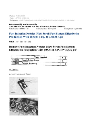
- 1. Product: TRACK LOADER Model: 943 TRACK LOADER 19Z Configuration: 943 LGP TRACK LOADER / HIGH DRIVE / 19Z00253-UP (MACHINE) POWERED BY 3204 ENGINE Disassembly and Assembly 3204 VEHICULAR ENGINE FOR 943 & 953 TRACK-TYPE LOADERS Media Number -SENR4214-00 Publication Date -01/04/1985 Date Updated -11/10/2001 Fuel Injection Nozzles (New Scroll Fuel System Effective In Production With 10X5411-Up, 45V36536-Up) SMCS - 1254-011; 1254-012 Remove Fuel Injection Nozzles (New Scroll Fuel System Effective In Production With 10X5411-UP, 45V36536-UP) START BY: a. remove valve cover (later) 1/3 943 LGP TRACK LOADER / HIGH DRIVE / 19Z00253-UP (MACHINE) POWERE... 2022/1/12 https://127.0.0.1/sisweb/sisweb/techdoc/techdoc_print_page.jsp?returnurl=/sis...
- 2. 1. Remove bolt (1) and retainer (2). 2. Remove fuel injection nozzle assembly (3) with tool (A). 3. Use tool (B) to clean the fuel injection nozzle bore. Use an open wrench or tap driver to turn tool (B). NOTE: The fuel injection nozzle is serviced as an assembly only. Install Fuel Injection Nozzles (New Scroll Fuel System Effective In Production With 10X5411-UP, 45V36536-UP) NOTICE Before the fuel injection nozzles are installed, check for fuel leakage, the pressure at which the injection nozzle opens, and the amount of fuel (spray pattern) that comes out of the nozzle with tool (A). See Testing Fuel Injection Nozzles in Testing And Adjusting. 2/3 943 LGP TRACK LOADER / HIGH DRIVE / 19Z00253-UP (MACHINE) POWERE... 2022/1/12 https://127.0.0.1/sisweb/sisweb/techdoc/techdoc_print_page.jsp?returnurl=/sis...
- 3. 1. Install washer (compression seal) (1), and use tool (B) to install carbon dam seal (2) on the fuel injection nozzle. 2. Install fuel injection nozzles (3) in the cylinder head. 3. Install retainer (4) and the bolt. END BY: a. install valve cover (later) 3/3 943 LGP TRACK LOADER / HIGH DRIVE / 19Z00253-UP (MACHINE) POWERE... 2022/1/12 https://127.0.0.1/sisweb/sisweb/techdoc/techdoc_print_page.jsp?returnurl=/sis...
- 4. Product: TRACK LOADER Model: 943 TRACK LOADER 19Z Configuration: 943 LGP TRACK LOADER / HIGH DRIVE / 19Z00253-UP (MACHINE) POWERED BY 3204 ENGINE Disassembly and Assembly 3204 VEHICULAR ENGINE FOR 943 & 953 TRACK-TYPE LOADERS Media Number -SENR4214-00 Publication Date -01/04/1985 Date Updated -11/10/2001 Fuel Injection Nozzles (Interim Scroll Fuel System) SMCS - 1254-011; 1254-012; 1254-015; 1254-016 1/9 943 LGP TRACK LOADER / HIGH DRIVE / 19Z00253-UP (MACHINE) POWERE... 2022/1/12 https://127.0.0.1/sisweb/sisweb/techdoc/techdoc_print_page.jsp?returnurl=/sis...
- 5. Remove Fuel Injection Nozzles (Interim Scroll Fuel System) START BY: a. remove rocker shaft assembly and push rods 2/9 943 LGP TRACK LOADER / HIGH DRIVE / 19Z00253-UP (MACHINE) POWERE... 2022/1/12 https://127.0.0.1/sisweb/sisweb/techdoc/techdoc_print_page.jsp?returnurl=/sis...
- 6. 1. Disconnect fuel injection nozzle (2) from adapter (1). 2. Remove bolt (3), the spacers and clamp that holds the fuel injection nozzle in place. NOTICE Never use force to remove the fuel injection nozzles. If necessary, turn and pull the fuel injection nozzle out of the cylinder head. 3. Pull adapter (1) out until the fuel injection nozzle can be removed. Remove fuel injection nozzle (2). Install Fuel Injection Nozzles (Interim Scroll Fuel System) NOTICE Before the fuel injection nozzles are installed, check for fuel leakage, the pressure at which the injection nozzle opens, and the amount of fuel (spray pattern) that comes out of the nozzle with tool (A). See Testing Fuel Injection Nozzles in Testing And Adjusting. 3/9 943 LGP TRACK LOADER / HIGH DRIVE / 19Z00253-UP (MACHINE) POWERE... 2022/1/12 https://127.0.0.1/sisweb/sisweb/techdoc/techdoc_print_page.jsp?returnurl=/sis...
- 7. 1. Remove carbon seal dam (2) with pliers. Remove compression seal (1). 2. Install a new compression seal on the nozzle. Install a new carbon seal dam with tool (B). 3. Use tool (C) to clean the bore for the fuel injection nozzle. 4. Install fuel injection nozzle (2) in the cylinder head. Push and turn to install the nozzle into its correct position. 5. Put engine oil on the bore in the cylinder head for adapter (1). Push adapter (1) in position, and connect the fuel injection nozzle to the adapter. Tighten the nut to a torque of 40 ± 7 N·m (30 ± 5 lb.ft.) with tool (D). NOTE: While the nut is tightened, hold the adapter with a wrench 90° ± 2° with the centerline of the fuel injection nozzle. 6. Install the spacers and clamp that hold the nozzle to the cylinder head. END BY: a. install rocker shaft assembly and push rods 4/9 943 LGP TRACK LOADER / HIGH DRIVE / 19Z00253-UP (MACHINE) POWERE... 2022/1/12 https://127.0.0.1/sisweb/sisweb/techdoc/techdoc_print_page.jsp?returnurl=/sis...
- 8. Disassemble Fuel Injection Nozzles (Interim Scroll Fuel System) START BY: a. remove fuel injection nozzles (interim scroll fuel system) NOTE: Do not diassemble any nozzle until a test has shown it is needed. Check each nozzle with tool (A) for leakage, the pressure at which the nozzle opens and the shape and amount of fuel (spray pattern) that comes out of the nozzle. Do not clean or make an adjustment to any nozzle that has a large (excessive) amount of return leakage. Excessive return leakage can be an indication of nozzle failures that cannot be corrected with an adjustment or cleaning and can cause engine damage. See Testing 9N3979 Fuel Injection Nozzles in Testing And Adjusting. NOTICE Keep the work area and all tools extra clean. Be careful not to cause damage to the parts while the nozzles are disassembled and assembled. 1. Remove cap (1) from the fuel injection nozzle. 5/9 943 LGP TRACK LOADER / HIGH DRIVE / 19Z00253-UP (MACHINE) POWERE... 2022/1/12 https://127.0.0.1/sisweb/sisweb/techdoc/techdoc_print_page.jsp?returnurl=/sis...
- 9. NOTICE If the lift adjustment screw is not turned counterclockwise one turn, the valve can be bent, or the seat for the valve can be damaged when the pressure adjustment screw is turned. 2. Put the nozzle in tool (B). Put tool (B) and the nozzle in a vise. Do not put any part of a nozzle directly in a vise. Loosen locknut (2) while the lift adjustment screw is held. Turn lift adjustment screw (3) counterclockwise one turn. Hold lift adjustment screw (3) with a 5/64" hex wrench, and remove locknut (2). 3. Loosen locknut (4) that holds the pressure adjustment screw. Use tool (D) to hold the pressure adjustment screw. 4. While the nozzle is held in one hand, tilt the nozzle, and remove the pressure adjusting screw and locknut, spring, seat and valve. 6/9 943 LGP TRACK LOADER / HIGH DRIVE / 19Z00253-UP (MACHINE) POWERE... 2022/1/12 https://127.0.0.1/sisweb/sisweb/techdoc/techdoc_print_page.jsp?returnurl=/sis...
- 10. 5. If the valve does not slide out of the nozzle, install tool (C), and remove valve as follows: a. Push the valve into the nozzle with tool (C) until the valve is against the bottom of the nozzle. b. Push down on the body of tool (C) to engage the collet on the valve with tool (C). c. Turn the nut counterclockwise, and remove valve from the nozzle body. Put the parts in solvent to loosen carbon and deposits of foreign material. The body is assembled with an epoxy material, and must not be in contact with the solvent for more than one to two hours. See Special Instruction, Form No. SEHS7292, for the correct method to clean the nozzle. Assemble Fuel Injection Nozzles (Interim Scroll Fuel System) NOTE: Make sure all of the parts have been thoroughly cleaned before the nozzles are assembled. Flush the body to remove any debris or lapping compound. 1. Put clean fuel on all of the parts. 2. Put valve (1) in position in the body as shown. 3. Install lift adjustment screw (6) into pressure screw (5). Turn the lift adjustment screw two or three turns. Install locknut (4) on the pressure adjustment screw (5). 7/9 943 LGP TRACK LOADER / HIGH DRIVE / 19Z00253-UP (MACHINE) POWERE... 2022/1/12 https://127.0.0.1/sisweb/sisweb/techdoc/techdoc_print_page.jsp?returnurl=/sis...
- 11. 4. Put spring (3), and seat (2) in position on adjustment screw (5). 5. Put seat (2) in contact with the valve, and push the valve into position in the body. Tighten the pressure screw by hand. 6. Make an adjustment to the opening pressure of the nozzle as controlled by the pressure adjustment screw with tool (B). See Testing 9N3979 Fuel Injection Nozzles, Opening Pressure Test in Tesing And Adjusting. 7. Make an adjustment to the valve lift as controlled by the lift adjustment screw with tool (B). See Testing 9N3979 Fuel Injection Nozzles, Valve Lift Adjustment in Testing And Adjusting. 8. Put the nozzle in position on tool (A). Put tool (A) and the nozzle in a vise. Hold lift adjustment screw (7) with a 5/64" hex wrench, and tighten locknut (8) until the adjustment screw will not turn. 9. Tighten the locknut for pressure adjustment screw to a torque of 8.0 to 9.1 N·m (70 to 80 lb.in.). 10. Tighten the locknut for the lift adjustment screw to a torque of 4.0 to 5.1 N·m (35 to 45 lb.in.). 8/9 943 LGP TRACK LOADER / HIGH DRIVE / 19Z00253-UP (MACHINE) POWERE... 2022/1/12 https://127.0.0.1/sisweb/sisweb/techdoc/techdoc_print_page.jsp?returnurl=/sis...
- 12. 11. Install the cap on the fuel injection nozzle. Use tool (C) to tighten the cap to a torque of 12.4 to 13.6 N·m (110 to 120 lb.in.). END BY: a. install fuel injection nozzles (interim scroll fuel system) 9/9 943 LGP TRACK LOADER / HIGH DRIVE / 19Z00253-UP (MACHINE) POWERE... 2022/1/12 https://127.0.0.1/sisweb/sisweb/techdoc/techdoc_print_page.jsp?returnurl=/sis...
- 13. Product: TRACK LOADER Model: 943 TRACK LOADER 19Z Configuration: 943 LGP TRACK LOADER / HIGH DRIVE / 19Z00253-UP (MACHINE) POWERED BY 3204 ENGINE Disassembly and Assembly 3204 VEHICULAR ENGINE FOR 943 & 953 TRACK-TYPE LOADERS Media Number -SENR4214-00 Publication Date -01/04/1985 Date Updated -11/10/2001 Fuel Injection Pump Housing And Governor (Interim Scroll Fuel System) SMCS - 1286-011; 1286-012 Remove Fuel Injection Pump Housing And Governor (Interim Scroll Fuel System) START BY: a. remove fuel injection lines (interim scroll fuel system) NOTE: The radiator guard, engine enclosure and fan were removed for better photo illustration only. 1/10 943 LGP TRACK LOADER / HIGH DRIVE / 19Z00253-UP (MACHINE) POWERE... 2022/1/12 https://127.0.0.1/sisweb/sisweb/techdoc/techdoc_print_page.jsp?returnurl=/sis...
- 14. 1. Close the fuel valve on the fuel tank. Remove fuel lines (1) and (2). 2. Disconnect governor linkage (3) from the governor. 3. Disconnect the two wires from fuel pressure switch (4) on the fuel filter base. 4. Remove fuel lines (5) and (6). Put plugs or caps on all fuel line openings. 5. Step 5 is for earlier 943's. Remove four bolts (7), and remove bracket (8) and the fuel filter base. Move plate (9) and the fuel lines clear of the engine. 6. Step 6 is for later 943's and 953's. Remove the fuel filter. Remove the two bolts that hold bracket (10) in place, and move the bracket and fuel lines clear of the engine. 2/10 943 LGP TRACK LOADER / HIGH DRIVE / 19Z00253-UP (MACHINE) POWERE... 2022/1/12 https://127.0.0.1/sisweb/sisweb/techdoc/techdoc_print_page.jsp?returnurl=/sis...
- 15. 7. Remove bolts (11) that hold the fuel injection pump housing to the oil manifold for the engine oil cooler. NOTE: When bolt (12) is removed, do not let the spacer on the back side between the fuel block and the alternator bracket fall under the engine. 8. Remove bolt (12) from the alternator bracket, and remove the spacer from the back side of the alternator bracket. 9. Remove bolt (13) and plug (14) from the timing gear cover. Use tool (B), if necessary, to remove the timing gear cover. 10. Loosen bolt (15) in the timing gear a maximum of one turn. 3/10 943 LGP TRACK LOADER / HIGH DRIVE / 19Z00253-UP (MACHINE) POWERE... 2022/1/12 https://127.0.0.1/sisweb/sisweb/techdoc/techdoc_print_page.jsp?returnurl=/sis...
- 16. 11. Loosen three nuts (16) that hold the pump drive to the timing gear plate until the nuts are even with the end of the studs. 12. Pull the fuel injection pump housing and pump drive away from the timing gear plate until the timing gear is against the front side of the timing gear plate. 13. Install tooling (A) in the timing gear cover to push the pump drive shaft, and loosen the timing gear on the shaft as follows: NOTICE The tooling must be installed in the position shown so the locks will not damage the water passage in the timing gear cover. a. Install tooling (A) in the position shown, and tighten the locks to hold the tooling in place. b. Turn the extension counterclockwise to loosen the bolt in the timing gear. As the bolt is loosened, it will push against tooling (A) and push the shaft of the pump drive through the timing gear to loosen the timing gear on the shaft. c. Remove tooling (A) from the timing gear cover. Remove the bolt and washer from the timing gear. 14. Remove three nuts (16), and remove the pump drive, fuel injection pump housing and governor (17) as a unit from the engine. Weight is 23 kg (50 lb.). Install Fuel Injection Pump Housing And Governor (Interim Scroll Fuel System) 4/10 943 LGP TRACK LOADER / HIGH DRIVE / 19Z00253-UP (MACHINE) POWERE... 2022/1/12 https://127.0.0.1/sisweb/sisweb/techdoc/techdoc_print_page.jsp?returnurl=/sis...
- 17. 1. Install the bolt and washer in shaft (1) in the pump drive. Remove the plug from the pump drive housing, and install tool (A) in the plug hole. Turn shaft (1) until timing pin (1) engages in the notch in the shaft. Tool (A) will hold the fuel injection pump camshaft in the correct position to set the fuel injection timing of the engine. 2. Be sure O-ring seals (2) are in position on the oil manifold for the engine oil cooler. Be sure the O-ring seal is in position on the pump drive housing. 5/10 943 LGP TRACK LOADER / HIGH DRIVE / 19Z00253-UP (MACHINE) POWERE... 2022/1/12 https://127.0.0.1/sisweb/sisweb/techdoc/techdoc_print_page.jsp?returnurl=/sis...
- 18. NOTICE Be extra careful not to damage O-ring seals (2) when the fuel injection pump housing and governor are installed. 3. Put the governor, fuel injection pump housing (3) and the pump drive in position on the engine as a unit. Install the three nuts that hold the pump drive to the timing gear plate. 4. Be sure the threads on bolt (4) and the threads in the shaft of the pump drive are not damaged. Put clean oil on the threads. 5. Install bolt (4) and the washer to hold the timing gear on the shaft. Tighten bolt (4) finger tight only. NOTE: Bolt (4) must be tight enough to hold the gear clearance (backlash) out of the timing gears when the engine is turned, but the timing gear must be able to turn on the shaft when the engine is turned to put the No. 1 piston on top center compression position (TDC). 6. Put No. 1 piston at the top center compression position (TDC) with the following procedure: a. Remove plug (5) from the flywheel housing. 6/10 943 LGP TRACK LOADER / HIGH DRIVE / 19Z00253-UP (MACHINE) POWERE... 2022/1/12 https://127.0.0.1/sisweb/sisweb/techdoc/techdoc_print_page.jsp?returnurl=/sis...
- 19. NOTE: Never turn the crankshaft backward to install the timing bolt in the flywheel. b. Turn the crankshaft clockwise (as seen from the front of the engine) until a 3/8"-16 NC bolt (6) at least two inches long can be installed through the timing hole in the flywheel housing and into the hole in the flywheel. c. Remove cover (7) from the valve cover. Check to see if both rocker arms for the No. 1 piston can be moved backward and forward by hand. NOTE: The No. 1 piston is at the top center compression position when the bolt is installed in the flywheel, and both rocker arms for No. 1 piston can be moved backward and forward. If both rocker arms cannot be moved, the No. 1 piston is not at the top center compression position. Remove the bolt from the flywheel. Turn the crankshaft clockwise (as seen from the front of the engine) one full turn (360°), and install the bolt again. 7. With the timing pin in the fuel injection pump housing and the timing bolt in the flywheel, tighten the bolt in the timing gear to a torque of 149 ± 7 N·m (110 ± 5 lb.ft.). 8. Check the timing as follows: a. Remove both the timing pin and timing bolt. b. Turn the crankshaft clockwise (as seen from the front of the engine) two full turns and install the timing pin and bolt again. c. The timing is correct if both the timing pin and timing bolt can be installed at the same time. The timing procedure must be done again if the timing pin and timing bolt cannot be installed at the same time. d. Remove the timing pin and timing bolt when the timing is correct. 7/10 943 LGP TRACK LOADER / HIGH DRIVE / 19Z00253-UP (MACHINE) POWERE... 2022/1/12 https://127.0.0.1/sisweb/sisweb/techdoc/techdoc_print_page.jsp?returnurl=/sis...
- 20. 9. Install bolts (8) that hold the fuel injection pump housing to the oil manifold for the engine oil cooler. 10. Install plug (5) in the flywheel housing. 11. Install cover (7) on the valve cover. 12. Install plug (9) in the fuel injection pump housing. 8/10 943 LGP TRACK LOADER / HIGH DRIVE / 19Z00253-UP (MACHINE) POWERE... 2022/1/12 https://127.0.0.1/sisweb/sisweb/techdoc/techdoc_print_page.jsp?returnurl=/sis...
- 21. 13. Be sure the O-ring seal is in position on plug (12), and put clean oil on the O-ring seal. Put plug (12) in position in the timing gear cover, and install the bolt and washer that hold it in place. 14. Put bolt (10) in position in the alternator bracket. Put spacer (11) in position on the back of the alternator bracket, and install bolt (10) through spacer (11) and into the fuel block. 15. Step 15 is for earlier 943's. Put plate (13) and bracket (14) for the fuel base in position on the earlier oil cooler, and install the four bolts that hold them in place. 16. Step 16 is for later 943's and 953's. Put bracket (14) for the fuel filter base in position on the oil manifold, and install the two bolts that hold it in place. Install the fuel filter. 17. Install fuel lines (15) and (16). 9/10 943 LGP TRACK LOADER / HIGH DRIVE / 19Z00253-UP (MACHINE) POWERE... 2022/1/12 https://127.0.0.1/sisweb/sisweb/techdoc/techdoc_print_page.jsp?returnurl=/sis...
- 22. 18. Install fuel lines (18) and (20). Open the fuel valve on the fuel tank. 19. Connect the two wires to fuel pressure switch (19). 20. Connect governor linkage (17) to the governor lever. END BY: a. install fuel injection lines (interim scroll fuel system) 10/10 943 LGP TRACK LOADER / HIGH DRIVE / 19Z00253-UP (MACHINE) POWE... 2022/1/12 https://127.0.0.1/sisweb/sisweb/techdoc/techdoc_print_page.jsp?returnurl=/sis...
- 23. Product: TRACK LOADER Model: 943 TRACK LOADER 19Z Configuration: 943 LGP TRACK LOADER / HIGH DRIVE / 19Z00253-UP (MACHINE) POWERED BY 3204 ENGINE Disassembly and Assembly 3204 VEHICULAR ENGINE FOR 943 & 953 TRACK-TYPE LOADERS Media Number -SENR4214-00 Publication Date -01/04/1985 Date Updated -11/10/2001 Fuel Injection Pump Housing And Governor (New Scroll Fuel System Effective In Production With 10X5411-UP, 45V36536-UP) SMCS - 1206-011; 1286-012 Remove Fuel Injection Pump Housing And Governor (New Scroll Fuel System Effective In Production With 10X5411- UP, 45V36536-UP) START BY: a. remove fuel injection lines (new scroll fuel system effective in production with 10X5411-UP, 45V36536) b. remove fuel transfer pump (new scroll fuel system effective in production with 10X5411-UP, 45V36536) 1/9 943 LGP TRACK LOADER / HIGH DRIVE / 19Z00253-UP (MACHINE) POWERE... 2022/1/12 https://127.0.0.1/sisweb/sisweb/techdoc/techdoc_print_page.jsp?returnurl=/sis...
- 24. Suggest: For more complete manuals. Please go to the home page. https://www.ebooklibonline.com If the above button click is invalid. Please download this document first, and then click the above link to download the complete manual. Thank you so much for reading
- 25. 1. Remove bolt (2) and fuel line (1). 2. Remove three bolts (3) that fasten manifold (4) to the governor housing. 3. Remove bolt (6) and plug (5) from the timing gear cover. 4. Loosen bolt (7) in the fuel pump drive gear a maximum of one turn. 2/9 943 LGP TRACK LOADER / HIGH DRIVE / 19Z00253-UP (MACHINE) POWERE... 2022/1/12 https://127.0.0.1/sisweb/sisweb/techdoc/techdoc_print_page.jsp?returnurl=/sis...
- 26. 5. Loosen two lower nuts (8) that fasten the fuel injection pump housing to the timing gear plate. Turn the nuts till they are even with the end of the studs. 6. Loosen upper fuel injection pump mounting nut (9). 7. Pull the fuel injection pump housing away from the timing gear plate. 8. Install tooling (A) or (B) in the timing gear cover to push the pump drive shaft, and loosen the timing gear on the shaft. If tooling (A) is used, proceed as follows: NOTICE The tooling must be installed in the position shown so the locks will not damage the water passage in the timing gear cover. 3/9 943 LGP TRACK LOADER / HIGH DRIVE / 19Z00253-UP (MACHINE) POWERE... 2022/1/12 https://127.0.0.1/sisweb/sisweb/techdoc/techdoc_print_page.jsp?returnurl=/sis...