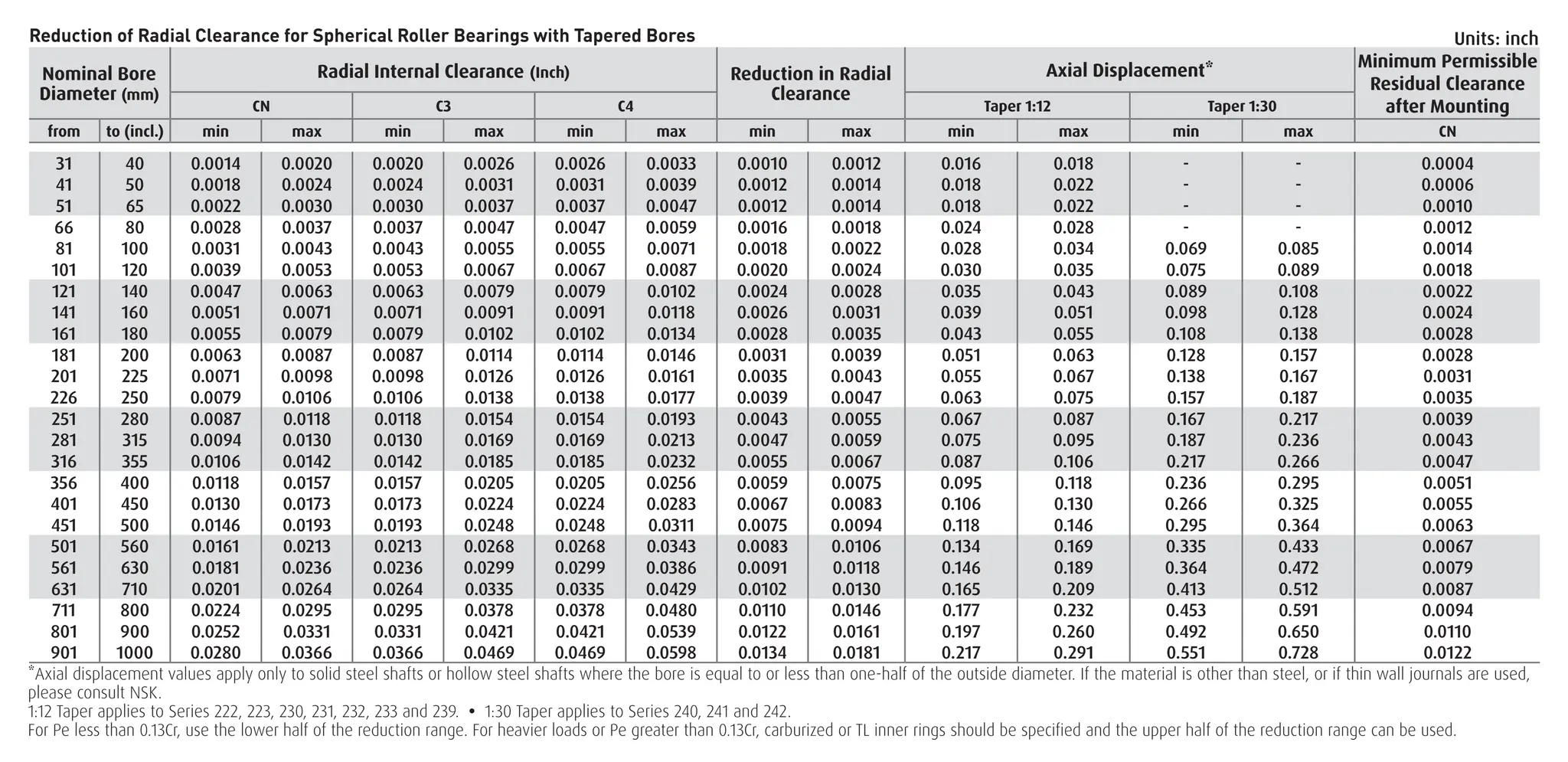
Reduction of RadialClearance for Spherical Roller Bearings with Tapered Bores
Nominal Bore
Diameter (mm)
Radial Internal Clearance (Inch) Reduction in Radial
Clearance
Axial Displacement* Minimum Permissible
Residual Clearance
after Mounting
CN C3 C4 Taper 1:12 Taper 1:30
from to (incl.) min max min max min max min max min max min max CN
31 40 0.0014 0.0020 0.0020 0.0026 0.0026 0.0033 0.0010 0.0012 0.016 0.018 - - 0.0004
41 50 0.0018 0.0024 0.0024 0.0031 0.0031 0.0039 0.0012 0.0014 0.018 0.022 - - 0.0006
51 65 0.0022 0.0030 0.0030 0.0037 0.0037 0.0047 0.0012 0.0014 0.018 0.022 - - 0.0010
66 80 0.0028 0.0037 0.0037 0.0047 0.0047 0.0059 0.0016 0.0018 0.024 0.028 - - 0.0012
81 100 0.0031 0.0043 0.0043 0.0055 0.0055 0.0071 0.0018 0.0022 0.028 0.034 0.069 0.085 0.0014
101 120 0.0039 0.0053 0.0053 0.0067 0.0067 0.0087 0.0020 0.0024 0.030 0.035 0.075 0.089 0.0018
121 140 0.0047 0.0063 0.0063 0.0079 0.0079 0.0102 0.0024 0.0028 0.035 0.043 0.089 0.108 0.0022
141 160 0.0051 0.0071 0.0071 0.0091 0.0091 0.0118 0.0026 0.0031 0.039 0.051 0.098 0.128 0.0024
161 180 0.0055 0.0079 0.0079 0.0102 0.0102 0.0134 0.0028 0.0035 0.043 0.055 0.108 0.138 0.0028
181 200 0.0063 0.0087 0.0087 0.0114 0.0114 0.0146 0.0031 0.0039 0.051 0.063 0.128 0.157 0.0028
201 225 0.0071 0.0098 0.0098 0.0126 0.0126 0.0161 0.0035 0.0043 0.055 0.067 0.138 0.167 0.0031
226 250 0.0079 0.0106 0.0106 0.0138 0.0138 0.0177 0.0039 0.0047 0.063 0.075 0.157 0.187 0.0035
251 280 0.0087 0.0118 0.0118 0.0154 0.0154 0.0193 0.0043 0.0055 0.067 0.087 0.167 0.217 0.0039
281 315 0.0094 0.0130 0.0130 0.0169 0.0169 0.0213 0.0047 0.0059 0.075 0.095 0.187 0.236 0.0043
316 355 0.0106 0.0142 0.0142 0.0185 0.0185 0.0232 0.0055 0.0067 0.087 0.106 0.217 0.266 0.0047
356 400 0.0118 0.0157 0.0157 0.0205 0.0205 0.0256 0.0059 0.0075 0.095 0.118 0.236 0.295 0.0051
401 450 0.0130 0.0173 0.0173 0.0224 0.0224 0.0283 0.0067 0.0083 0.106 0.130 0.266 0.325 0.0055
451 500 0.0146 0.0193 0.0193 0.0248 0.0248 0.0311 0.0075 0.0094 0.118 0.146 0.295 0.364 0.0063
501 560 0.0161 0.0213 0.0213 0.0268 0.0268 0.0343 0.0083 0.0106 0.134 0.169 0.335 0.433 0.0067
561 630 0.0181 0.0236 0.0236 0.0299 0.0299 0.0386 0.0091 0.0118 0.146 0.189 0.364 0.472 0.0079
631 710 0.0201 0.0264 0.0264 0.0335 0.0335 0.0429 0.0102 0.0130 0.165 0.209 0.413 0.512 0.0087
711 800 0.0224 0.0295 0.0295 0.0378 0.0378 0.0480 0.0110 0.0146 0.177 0.232 0.453 0.591 0.0094
801 900 0.0252 0.0331 0.0331 0.0421 0.0421 0.0539 0.0122 0.0161 0.197 0.260 0.492 0.650 0.0110
901 1000 0.0280 0.0366 0.0366 0.0469 0.0469 0.0598 0.0134 0.0181 0.217 0.291 0.551 0.728 0.0122
*Axial displacement values apply only to solid steel shafts or hollow steel shafts where the bore is equal to or less than one-half of the outside diameter. If the material is other than steel, or if thin wall journals are used,
please consult NSK.
1:12 Taper applies to Series 222, 223, 230, 231, 232, 233 and 239. • 1:30 Taper applies to Series 240, 241 and 242.
For Pe less than 0.13Cr, use the lower half of the reduction range. For heavier loads or Pe greater than 0.13Cr, carburized or TL inner rings should be specified and the upper half of the reduction range can be used.
Units: inch
2.
Mounting of SphericalRoller Bearings with Tapered Bores
Bearings with tapered bores are mounted on tapered
shafts or adapters (Figs. 1 and 2).
The internal clearance of a bearing varies with the axial
movement of the taper. Check the clearance before
mounting the bearing. Axially displace the bearing until
the radial clearance reduction equals the value calculated
on the reverse side.
Measure radial clearance during mounting with a feeler
gauge. As shown in Fig. 3, the clearances for both rows of
rollers must be measured simultaneously, and these two
values should be kept roughly the same by adjusting the
relative position of the outer and inner rings.
The average of these two measurements, taken for both
rows, may be used as the residual internal clearance.
Measuring Clearance of Large Size
Spherical Roller Bearings
When a large bearing is mounted on a shaft, the outer ring
may be deformed into an oval shape by its own weight.
If the clearance is measured at the top of the deformed
bearing, the measured value may be smaller than the true
value. If an incorrect radial internal clearance is obtained in this
manner and the values in the table on the reverse side of this
card are used, then the actual interference fit may become too
small. In large bearings (over 200mm) measurements should
be taken at locations a, b, and c (shown on Fig. 4 below) and
entered into the following equation:
radial clearance = (a + b + c)/2
Determining Bearing Bore Size
Note: To obtain bore size, multiply the last two digits
of part number by 5; e.g. part 22314 (14 x 5 = 70mm
bore). Part numbers with bore sizes 500mm and larger
are written with a slash, followed by the actual bore
size; e.g. 232/710 (710 = bore size).
Example: The bearing to be mounted is a
22340CAMKE4C3 [200mm bore (40x5) with C3
clearance].
1. Using feeler gauges, the clearance in the bearing
measures .0090”.
2.From the “Reduction in Radial Clearance” column in
the chart, the reduction in clearance is .0031” to
.0039”. Subtract these numbers from the measured
clearance.
Measured Clearance .0090” .0090”
Reduction .0031” .0039”
Mounted Clearance .0059” .0051”
3.Bearing is installed by one of the recommended
methods until the clearance in the bearing is within
the mounted clearance range. For best results, mount
bearing at the middle of the range.
A118
Fig. 14.4 Mounting with Adapter Fig. 14.5 Mounting with Withdrawal Sleeve
Oil
apter Fig. 14.5 Mounting with Withdrawal Sleeve
Mounting with Adapter Mounting with Withdrawal
Sleeve
Fig. 1 Fig. 2
Fig. 3 Fig. 4
Measuring Clearance of
Spherical Roller Bearing
Measuring Clearance of Large
Size Spherical Roller Bearing
03/15
![Mounting of Spherical Roller Bearings with Tapered Bores
Bearings with tapered bores are mounted on tapered
shafts or adapters (Figs. 1 and 2).
The internal clearance of a bearing varies with the axial
movement of the taper. Check the clearance before
mounting the bearing. Axially displace the bearing until
the radial clearance reduction equals the value calculated
on the reverse side.
Measure radial clearance during mounting with a feeler
gauge. As shown in Fig. 3, the clearances for both rows of
rollers must be measured simultaneously, and these two
values should be kept roughly the same by adjusting the
relative position of the outer and inner rings.
The average of these two measurements, taken for both
rows, may be used as the residual internal clearance.
Measuring Clearance of Large Size
Spherical Roller Bearings
When a large bearing is mounted on a shaft, the outer ring
may be deformed into an oval shape by its own weight.
If the clearance is measured at the top of the deformed
bearing, the measured value may be smaller than the true
value. If an incorrect radial internal clearance is obtained in this
manner and the values in the table on the reverse side of this
card are used, then the actual interference fit may become too
small. In large bearings (over 200mm) measurements should
be taken at locations a, b, and c (shown on Fig. 4 below) and
entered into the following equation:
radial clearance = (a + b + c)/2
Determining Bearing Bore Size
Note: To obtain bore size, multiply the last two digits
of part number by 5; e.g. part 22314 (14 x 5 = 70mm
bore). Part numbers with bore sizes 500mm and larger
are written with a slash, followed by the actual bore
size; e.g. 232/710 (710 = bore size).
Example: The bearing to be mounted is a
22340CAMKE4C3 [200mm bore (40x5) with C3
clearance].
1. Using feeler gauges, the clearance in the bearing
measures .0090”.
2.From the “Reduction in Radial Clearance” column in
the chart, the reduction in clearance is .0031” to
.0039”. Subtract these numbers from the measured
clearance.
Measured Clearance .0090” .0090”
Reduction .0031” .0039”
Mounted Clearance .0059” .0051”
3.Bearing is installed by one of the recommended
methods until the clearance in the bearing is within
the mounted clearance range. For best results, mount
bearing at the middle of the range.
A118
Fig. 14.4 Mounting with Adapter Fig. 14.5 Mounting with Withdrawal Sleeve
Oil
apter Fig. 14.5 Mounting with Withdrawal Sleeve
Mounting with Adapter Mounting with Withdrawal
Sleeve
Fig. 1 Fig. 2
Fig. 3 Fig. 4
Measuring Clearance of
Spherical Roller Bearing
Measuring Clearance of Large
Size Spherical Roller Bearing
03/15](https://image.slidesharecdn.com/rollerbearingclearancechart-231222083428-2aad73b5/75/Roller-Bearing-Clearance-Chart-for-Reference-2-2048.jpg)


