
Recommended
Recommended
More Related Content
Similar to Case ih case international 235 h tractor service repair manual
Similar to Case ih case international 235 h tractor service repair manual (16)
More from fujjdfjjskekmm
More from fujjdfjjskekmm (20)
Recently uploaded
Recently uploaded (20)
Case ih case international 235 h tractor service repair manual
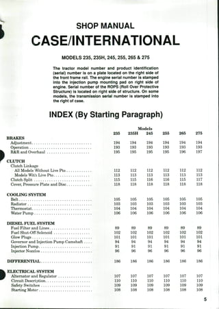
- 1. SHOP MANUAL CASE/INTERNATIONAL MODELS 235, 235H, 245, 255, 265 & 275 The tractor model number and product identification (seriai) number is on a plate iocated on the right side of the front frame raii. The engine seriai number is stamped into the injection pump mounting pad on right side of engine. Serial number of the ROPS (Roii Over Protective Structure) is iocated on right side of structure. On some modeis, the transmission seriai number is stamped into the right of case. INDEX (By Starting Paragraph) BRAKES Adjustment Operation R&R and Overhaul CLUTCH Clutch Linkage All Models Without Live Pto Models Witli Live Pto Clutch Split Cover, Pressure Plate and Disc COOLING SYSITEM Belt Radiator Thermostat Water Pump DIESEL FUEL SYSTEM Fuel Filter and Lines Fuel Shut-Off Solenoid Glow Plugs Grovemor and Injection Pump Camshaft Injection Pump Injector Nozzles DIFFERENTLSkL ELECTRICAL SYSTEM Alternator and Regulator Circuit Description Safety Switches Starting Motor 235 194 193 195 112 113 115 118 105 103 104 106 89 102 101 94 91 96 Models 235H 194 193 195 112 113 115 118 105 103 104 106 89 102 101 94 91 96 245 194 193 195 112 113 116 118 105 103 104 106 89 102 101 94 91 96 255 194 193 195 112 113 116 118 105 103 104 106 89 102 101 94 91 96 265 194 193 196 112 113 115 118 105 103 104 106 89 102 101 94 91 96 275 194 193 197 112 113 117 118 105 103 104 106 89 102 101 94 91 96 186 186 186 186 186 186 107 110 109 108 107 110 109 108 107 110 109 108 107 110 109 108 107 110 109 108 107 110 109 108
- 2. INDEX (CONT.) ENGINE Cam Followers Camshaft Connecting Rods and Bearings Crankshaft and Main Bearings Crankshaft Seals Cylinder Head Flywheel Maintenance. Oil Pan Oil Pump Pistons, Cylinder Block and Rings R&R Engine Assembly Rocker Arms and Push Rods Rod and Piston Units Timing Gears Timing Gear Cover Valve Clearance . Valve Springs Valves, Guides and Seats FINAL DRIVE FRONT AXLE SYSTEM (TWO-WHEEL DRIVE) Axle Main Member Spindles and Bushings Steering Bellcrank Tie Rod and Toe-In Tires, Wheels and Bearings Tread Adjustment and Drag Link Non-Adjustable Axle FRONT-WHEEL-DRIVE SYSTEM Axle and Steering Linkage Differential Differential Bevel Pinion Front Drive Spindles and Inner Axles Front Final Drives and Wheel Axles Front Wheel Drive Maintenance HYDRAULIC LIFT SYSTEM Auxiliary Valve Fluid and Filters Hydraulic Pump Lift Cover Troubleshooting Tests and Adjustments MANUAL STEERING SYSTEM POWER STEERING SYSTEM 6 235 74 78 81 82 83 69 85 64 87 86 80 68 73 79 75 77 70 72 71 Models 235H 74 78 81 82 83 69 85 64 87 86 80 68 73 79 75 77 70 72 71 245 74 78 81 82 83 69 85 64 87 86 80 68 73 79 75 11 70 72 71 255 74 78 81 82 83 69 85 64 87 86 80 68 73 79 75 11 70 72 71 265 74 78 81 82 83 69 85 64 87 86 80 68 73 79 75 77 70 72 71 27{ 74 78 81 82 83 69 85 64 87 86 80 68 73 79 75 77 70 72 71 187 44 187 44 187 187 44 54 44 54 189 47 57 191 9 5 ••• 2 1 13 16 18 23 22 21 20 24 17 216 202 212 214 203 204 9 5 2 1 13 16 18 23 22 21 20 24 17 216 202 212 214 203 204 10 6 ... 4 1 14 25 27 32 31 30 29 33 26 216 202 212 214 203 205 10 6 2 1 14 25 27 32 31 30 29 33 26 216 202 212 214 203 205 11 7 3 1 14 ... ... ... ... ... 216 202 212 214 203 209 12 8 15 4 1 14 34 36 41 40 39 38 42 35 216 202 212 214 203 211 50 60
- 3. INDEX (CONT.) 235 POWER TAKE OFF 199 TRANSMISSION (235H HYDROSTATIC) Hydrostatic Unit Lubrication. Overhaul Range Transmission Tests and Adjustments Troubleshooting TRANSMISSION (235 SLIDING GEAR) Inspection 120 Lubrication 121 Overhaul 123 Remove and Reinstall 122 TRANSMISSION (245, 255 AND 265 CONSTANT MESH) Inspection Lubrication Overhaul Remove and Reinstall TRANSMISSllON (245, 255 AND 265 SYNCHROMESH) Inspection Lubrication Overhaul Range Transmission Remove and Reinstall TRANSMISSl ON (275 MODEL) Hydraulic Clutch Inspection Lubrication Overhaul Remove and Reinstall . Models 235H 199 181 175 182 183 177 176 245 200 ... •.* ... ... 255 200 ... ... ... 265 200 ... ... 275 199 ... ... ... 133 134 136 135 144 145 147 155 146 .... ... ... 133 134 136 135 144 145 147 155 146 ... ... ... 133 134 136 135 144 145 147 155 146 ... ... ... ... ... ... ... ... 171 161 162 166 163 DUAL DIMENSIONS This service manual provides specifications in both U.S. Customary and Metric (SI) systems of measurement. The first specification is given in the measuring system perceived by us to be the preferred system when servicing a particular component, while the second specification (given in parenthesis) is the converted measurement. For instance, a specification of 0.011 inch (0.28 mm) would indicate that we feel the preferred measurement in this instance is the U.S. Customary system of measiurement and the Metric equivalent of 0.011 inch is 0.28 mm.
- 4. CONDENSED SERVICE DATA 235, 235H 245 GENERAL Engine Make Engine Model Number of Cylinders Bore Stroke Displacement Compression Ratio TXJNE-UP Firing Order Valve Clearance, Cold — Inlet Exhaust Valve Face and Seat Angle Inlet Exhaust Injector — Opening Pressure Engine Low Idle Engine High Idle Engine Rated Speed Battery — Voltage Ground Transmission — Types Available Speeds — Sliding gear , Hydrostatic , Constant mesh S3nic SIZES Crankshaft Main Journal Diameter Crankshaft Crankpin Diameter Piston Pin Diameter Valve Stem Diameter K3B K3D Models 255 -Mitsubishi K3E 3 265 275 i K3H K3M 68 mm (2.677 in.) 73 mm (2.874 in.) — 78 mm— 76 mm (2.992 in.) 78 mm 84 mm (3.071 in.) (3.307 in.) 90 mm (3.071 in.) (3.543 in.) 849 cc 979 cc 1061 cc 1290 cc 1496 cc (51.81 cu.in.) (59.74 cu.in.) (64.75 cu.in.) (78.72 cu.in.) (91.29 cu.in.) 23:1 1-3-2 -0.25 mm - (0.010 in.) -0.25 mm - (0.010 in.) 45° 45° -10,789-12,749 kPa (1565-1849 psi) 900-950- —14,714-16,672 kPa — (2134-2418 psi) i -2825-2900- 2700 2700 2800 2700 2825-2880 2700 12 Negative t 6F-2R Variable x 2 -9F-3R -9F - 3R- -52 mm- (2.0472 in.) — 57 mm— (2.44 in.) 42 mm- (1.6535 in.) —19 mm — (0.905 in.) 48 mm — (1.890 in.) 23 mm —6.6 mm - (0.2598 in.) (0.905 in.) 8.0 mm- (0.3150 in.) 8
- 5. CONDENSED SERVICE DATA (CONT.) CLEARANCES Main Bearing, Diametral Clearance, Miiximum Rod Bearing D iametral Clearance, Miaximum Camshaft Bearing, Diametral Clearance, Maximum — Front Crankshaft End Play, Maximum CAPACITIES Cooling System Crankcase With Filter Transmission — Constant Mesh Sliding Gear Synchronized Hydrostatic Front Drive Axle 235,235H 6L (6.34 qt.) 3.5 L (3.70 qt.) 12 L (3.17 gal.) 14 L (3.70 gal.) 2.5 L (2.6 qt.) 245 Models 255 265 275 - 0.1 mm — (0.004 in.) —0.15 mm - (0.006 in.) —0.15 mm - (0.006 in.) — 0.1 mm — (0.004 in.) -5.3 L - (5.6 qt.) - 4.5 L - (4.8 qt.) 20 L- (5.3 gal.) 25 L- (6.6 gal.) - 3 . 5 L - (3.7 qt.) 5.8 (6.1 ( 46 (12.2 46 (12.2 L qt.) (5 L gal.) L gal.) 1 7 t, 1 .0 (6 qt.) 6L .34 qt.) # 7.3 L (7.7 qt.) * Model 235 is equipped with a sliding gear transmission and 235H model is equipped with a hydrostatic transmission. Both the sliding gear transmission and the variable speed (F/R) hydrostatic transmission are coupled to a two speed, range transmission. t Models 245, 255 and 265 may be equipped with either a constant mesh transmission or a synchromesh transmission. Both constant mesh and synchromesh transmissions are coupled to a three speed range transmission, which provide 9 forward and 3 reverse speeds. The constant mesh trguismission is used without live pto; the synchromesh transmission is used with live pto. t Model 275 tractors are equipped with a three forward and 1 reverse speed S3nichromesh transmission coupled to a three speed range transmission, which provides 9 forward and 3 reverse speeds. # On 275 models, capacity of the gear transmission is 6.5 L (1.7 gal.), capacity of the range transmission is 19 L (5.0 gal.), and capacity of the rear axle gear case is 3 L (0.8 gal.) for each side. 9
- 6. Paragraph 1 CASE/INTERNATIONAL FRONT AXLE SYSTEM (TWO-WHEEL DRIVE) TIRES, WHEELS AND BEARINGS All Two-Wheel-Drive Models 1, The front wheel bearings should be removed, cleaned, inspected and renewed or repacked with grease every 1000 hours ofoperation. % remove front wheel hub and bearings, raise and support the front axle, unbolt and remove the tire and wheel assembly, then remove cap (1—Fig. 1 or Fig. 2). On 235 and 235H models, straighten locking washer (3—Fig. 1), then remove nut (2) and lockwasher. On all except 235 and 235H niodels, reinove cotter pin, castellated nut (2—Fig. 2), and washer (3). On all models, use a suitable puller to remove t;he hub assembly from spindle axle shaft. Seal (3—Fig. 1 or Fig. 2) and inner bearing (6) will remain on spindle. Pack wheel bear- ings liberally with a suitable wheel bearing grease, such as Case IH 25X HEP. Reassemble by reversing disassembly procedure. On 235 and 235H models, install new locking washer (3—Fig. 1) and tighten nut (2) to 39-58 N.m (28-43 ft.-lbs.) torque, loosen nut until the rolling torque of wheel hub (5) is 0.6-0.8 N.m (6-7 in.-lbs.), then lock position of nut with tab of locking washer (3) and install cap (1). Tighten bolts retaining front wheel to hub to 118-132 N.m (87-98 ft.-lbs.) torque. On all except 235 and 235H models, tighten castel- lated nut (2—Fig. 2) to 39-58 N.m (28-43 ft.-lbs.) torque, loosen nut until the rolling torque of wheel hub (5) is 0.6-0.8 N.m (6-7 in.-lbs.), then lock position ofnut with cotter pin and install cap (1). Tighten bolts retaining front wheel to hub to 83-93 N.m (61-69 ft.-lbs.) torque. Rear wheel to axle hub bolts and rear axle stud nuts for 235 and 235H models should he tightened to 118-132 N.m (87-98 ft.-lhs.) torque. On 245, 255 and 275 models, the rear wheel to axle huh bolts should be tightened to 118-132 N.m (87-98 fb.-lbs.) torque and nuts securing rear wheel rim to wheel disc should he tightened to 152-172 N.m (112-127 ft.-lhs.) torque. Rear wheel disc to axle huh and rear wheel rim to wheel disc nuts should be tightened to 152-172 N.m (112-127 fb.-lbs.) torque for 265 models. On all models, lug bolt torque for all wheels should be checked after the first 10 hours ofoperation follow- ing installation and every 100 hours thereafter. | 25 Fig. I^Exploded view of front axie used on 235 models. Drag lini( (26) attaches to arm (17) and tie rod connects arms at- tached to tiie spindies (10 & 22). 1. Cap 2. Nut 3. Tab washer 4. Outer ball bearing 5. Wheel hub 6. Inner ball bearing 7. Spacer 8. Seal 10. Left spindle 11. "O" ring 12. Spacer 13. Thrust bearing 14. Bushings 15. Seal 16. Washer 17. Steering arm 19. Axle main member 20. Nut 21. Axle pivot 22. Right spindle 23. Nut 24. Washer 25. Front frame 26. Drag link 27. Nut 28. Steering arm 10
- 7. MODELS 23j>, 235H, 245, 255, 265 & 275 Paragraph 1 (Cont.) Some wheels can be reversed to change tread width on some tracto]r models, but certain wheels should only be installed one way and should not be reversed. Check with wheel or tractor manufacturer if proper installation method is not known. Refer to the follow- ing specifications for recommended inflation pres- sures. Actual air pressure should be adjusted to conform to the load on the tire and ground condition. Two-Wheel Drive 235 and 235H Front — Tire size 18 x 7.00-8-4 ply Tread type PD (G2) Max. Inflation Pressure 200 kPa (28 psi) Rim size 5.50-8 Tire size 4.00-9-4 ply Tread type F2 Max. Inflation Pressure 320 kPa (46 psi) Rim size 3.00D-9DT Tire size 4.50-10-4 ply Tread type FSR Max. Inflation Pressure 300 kPa (42 psi) Rim size 3.00D-10 Tire size 5.00-10-4 ply Tread type FSR Max. Inflation Pressure 280 kPa (40 psi) Rim size 3.00D-10 Tire size 20 x 8.00-10-4 ply Tread type . . . PD (G2) Max. Inflation Pressure 160 kPa (24 psi) Rim size 6.001-10 Rear — Tire size 8-16-4 ply Tread type FSLH Max. Inflation Pressure 100 kPa (14 psi) Rim size W6-16 Tire size 8-18-4 ply Tread type FSLH Max. Inflation Pressure . 83-159 kPa (12-23 psi) Rim size W6-18 Tire size 9.5-18-4 ply Tread type FD Max. Inflation Pressure . 83-138 kPa (12-20 psi) Rim size W8-18 Two-Wheel Drive 245 and 255 Front — Tire size 20 x 8.00-10-4 ply Tread type PD Max. Inflation Pressure 165 kPa (24 psi) Rim size 6.001 x lODT Tire size 24 x 8.50-14-4 ply TVead type PDl Max. Inflation Pressure 165 kPa (24 psi) Rim size 7JA-14 Tire size 4.00-15-4 ply Tread type F2 Max. Inflation Pressure 360 kPa (52 psi) 25 Fig. 2—Exploded view of front axie typicai of some 245 and 255 modeis. Refer to Fig. 3 for modeis witti adjust- abie tread axie. Upper steering arms, drag iinii and reiated parts for non-ad- Justabie axie are simiiar to those siiown in Fig. 3. 16. Woodruff key 18. "O" ring (25 mm) 19. Axle main member 20. Screws 21. Axle pivot 25. Front frame 29. Collar 30. Shims 31. Washer 32. "O" rings (25 mm) 1. Cap 2. Nut 3. Washer 4. Outer ball bearing ^ 5. Wheel hub 6. Inner ball bearing 8. Seal 9. Gasket 10. Left spindle 11. "Cring (38 mm) 13. Thrust bearing 14. Bushings 33. Bushings 11
- 8. Paragraph 2 CASE/INTERNATIONAL Rim size 3.00D x 15 Tire size 5.00-15-4 ply Tread type F2 Max. Inflation Pressure 300 kPa (44 psi) Rim size 3.00D x 15 Tire size 5.90-15-4 ply Tread type FI2 Max. Inflation Pressure 245 kPa (36 psi) Rim size 4.00E-15 Rear — Tire size 13.6-16-4 ply Tread type PDl Max. Inflation Pressure. 75-100 kPa (11-14 psi) Rim size W12 x 16 Tire size 9.5-24-4 ply Tread type Rl Max. Inflation Pressure. 85-135 kPa (12-20 psi) Rim size W7 x 24 Tire size 11.2-24-4 ply Tread type Rl Max. Inflation Pressure. 85-125 kPa (12-18 psi) Rim size W9-24 Two-Wheel Drive 265 Front — Tire size 24 x 8.50-14-4 ply Tread type PDl Max. Inflation Pressure 165 kPa (24 psi) Rim size 7JA-14 Tire size 5.50-16-4 ply Tread type F2 Max. Inflation Pressure 275 kPa (40 psi) Rim size 4.00E-16 Rear — Tire size 355/80D20-4 ply Tread type PDl Max. Inflation Pressure. 70-100 kPa (10-14 psi) Rim size Wll-20 Tire size . 12.4-24-4 ply Tread type Rl Max. Inflation Pressure. 85-110 kPa (12-16 psi) Rim size WlO-24 Tire size 11.2-28-4 ply Tread type Rl Max. Inflation Pressure. 85-125 kPa (12-18 psi) Rim size WlO-28 Tire size 11.2-36-4 ply Tread type Rl Max. Inflation Pressure. 85-125 kPa (12-18 psi) Rim size WlO-36 Two-Wheel Drive 275 Front — Tire size . 24 x 8.50-14-4 ply Tread type PDl Max. Inflation Pressure 165 kPa (24 psi) Rim size 7JA x 14 Tire size 5.00-15-4 ply Tread type AG Max. Inflation Pressure 255 kPa (37 psi) i Rim size 3.00D x 15 I Tire size 5.90-15-4 ply ^ Tread type ES Max. Inflation Pressure 215 kPa (31 psi) Rim size 4.00E x 15DC j Tire size 212/80D15-4 ply Tread type PDl ^ Max. Inflation Pressure 165 kPa (24 psi) Rim size 7JA x 15 Tire size 27 x 8.50-15-4 ply Tread type G2 Max. Inflation Pressure 205 kPa (30 psi) Rim size 7JA x 15 Tire size 5.50-16-4 ply Tread type F2 Max. Inflation Pressure 275 kPa (40 psi) Rim size 4.00E x 16 Tire size 6.00-16-4 ply Tread type F2 Max. Inflation Pressure 250 kPa (36 psi) Rim size 4.00 x 16 Rear — Tire size 18.4-16.1-4 ply Tread type G2 Max. Inflation Pressure 85 kPa (12 psi) Rim size 16 LB x 16.1 Tire size 355/80D20-4 ply Tread type PDl Max. Inflation Pressure . . 70-95 kPa (10-14 psi) Rim size Wll x 20 Tire size 11.2/10-24-4 ply Tread type ES Max. Inflation Pressure . . . . . . 115 kPa (17 psi) Rim size W9 x 24 Tire size 12.4-24-4 ply Tread type Rl Max. Inflation Pressure . 85-110 kPa (12-16 psi) Rim size WIO x 24 Tire size 13.6-24-4 ply Tread type Rl Max. Inflation Pressure 95 kPa (14 psi) Rim size Wll x 24 TIE ROD AND TOE-IN Two Wheel Drive 235, 235H, 245 And 255 Models 2. A single tie rod connects left and right steering arms of spindles (10 and 22—Fig. 1, Fig. 2 and Fig. 3) for 235, 235H, 245 and 255 models. Automotive type ends are not adjustable for wear and should be renewed if worn. Tighten nuts attaching tie rod ends to steering arms to 59-88 N.m (43-65 ft.-lbs.) torque. 12
- 9. MODELS 235, 235H, 245, 255, 265 & 275 Paragraphs 3-4 Fig. 3—Exploded view of adjustable axle used on some 245 and 255 models. 10. Left spindle 11. "O" ring 13. Thrust bearing 14. Bushing 17. Steering arm 18. "O" ring 19. Axle main naember 22. Right spindle 26. Drag link 27. Nut 28. Steering arm 31- Washer 32. "O" ring 33. Bushing 34. Axle extension 35. Right steering arm 36. Tie rod outer tube 37. Pin 38. Clamp 39. Inner tie rod 40. Locknut 41. Rod end 10- Rod ends tlireaded into tie rod are used to adjust the distance between ends and establish front wheel toe-in. Recon:Lmended toe-in is 4-8 mm (^/i6-^/l6 in.) and should he measured between wheel rims on cen- terline of axle, parallel to ground. Rotate wheels and re-measure tc be sure that wheels are not bent, giving incorrect reading. Tighten rod end jam nut (40—Fig. 3) to 59-88 N.m (43-65 ft.-lbs.) torque after toe-in is correctly set. Bolt for clamps (38) should be tightened to 25-29 N.m (18-22 ft.lbs.) torque. Holes in tie rod tubes, pins (37) and clamps (38) are used to adjust length of tie rods when changing width of adjustable axle as outlined in paragraph 14. Two Wheel Drive 265 Model 3. On 265 models, one tie rod connects left steering arm (17—Fig. 4) to steering arm (28) and a second tie rod connects right steering arm (35). Automotive type ends are not adjustable for wear and should be re- newed if worn. Holes for clamp bolts (37) in tie rods are used to adjust length of tie rods when changing adjustable axle width. It is important that both tie rods be adjusted to the same width and that width corresponds to the axle width. Refer to paragraph 14 when changing axle width. Rod ends (41) threaded into left side tie rod are used to change distance between ends and make fine adjustments to the front wheel toe-in. Tie rod end threaded into outer tube has left hand thread, per- mitting adjustment by turning tubes after loosening the rod end locknuts. Recommended toe-in is 4-8 mm (3/16-5/^6 in.) and should be measured between wheel rims on centerline of axle, parallel to ground. Rotate wheels and re-measure to be sure that wheels are not bent, giving incorrect reading. Tighten rod end jam nuts (40) to 59-88 N.m (43-65 ft.-lbs.) torque after toe-in is correctly set. Two Wheel Drive 275 Model 4. On 275 models, one tie rod connects left steering arm and spindle (10—Fig. 5) to the bellcrank (47— Fig. 6) and a second tie rod connects right steering arm. Automotive type ends are not adjustable for wear and should be renewed if worn. Rod ends (41) threaded into right side tie rod are used to adjust the distance between ends and establish front wheel toe- in. Tie rod end threaded into outer tube has left hand thread. Recommended toe-in is 4-8 mm (Vi6-^/i6 in.) and should be measured between wheel rims on cen- terline of axle, parallel to ground. Rotate wheels and re-measure to be sure that wheels are not bent, giving 13
- 10. Paragraph 5 incorrect reading. Tighten rod end jam nut (40) to 59-88 N.m (43-65 fl.-lbs.) torque after toe-in is cor- rectly set. Holes for clamp bolts (37) in tie rod are used to adjust length of tie rods when changing adjustable axle width. Clamp bolts (37) should be tightened to 29-34 N.m (22-25 ft.-lbs.) torque. CASE/INTERNATIONAL SPINDLES AND BUSHINGS Two Wheel Drive 235 Model 5. To remove spindle (10—Fig. 1) from left side, first raise and support axle on left side, then remove wheel i Fig. 4—Exploded view of adjustable axle used on 265 models. Axle Is offset to right side of engine centeriine. 10. Left spindle 11. "O" ring 12. Spacer 13. Thrust bearing 14. Bushings 15. Seal 16. WoodrufFkeys 17. Left steering arm 19, Axle main member 20. Pivot pin retaining screw 21. Axle pivot 22, Right spindle 25. Front frame 27. Nut 28. Steering arm 31. Washer 32. "O" rings (29 mm) 33. Bushings 34. Axle extension 35. Right steering arm 36. Tie rod outer tube 37. Tie rod clamp bolt 39. Inner tie rod 40. Locknut 41. Rod end i 14
- 11. MODELS 235, 235H, 245, 255, 265 & 275 Paragraph 5 (Cont.) Fig. 5—Expioded view of adjustfibiB axie used on 275 modeis. 10. Left spindle 11. "0" ring (42 mm) 13. Thrust bearing 14. Bushings 18. "O" ring (29 mm) 19. Axle main member ). 21. Axle pivot 22. Right spindle 23. Collar 24. Spring pin 25. Front frame 31. Wanher 32. "O" rings (29 mm) 33. Bushings 34. Axle extension 42. Axle pivot brackets Fig. 6—Expioded view of steering iiniC' age for 275 modeis. Shaft (48) is part of front frame (25—Fig. 5). 10. Left spindle 22. Right spindle 26. Drag link 27. Nut 28. Steering arm 36. Tie rod outer tube 37. Tie rod clamp bolt 39. Inner tie rod 40. Locknut 41. Rod end 43. Nut 44. Spacer (5 mm) 45. Sealing rings (30 mm) 46. Bushings 47. Bellcrank 48. Bellcrank shaft 15
- 12. Thank you very much for your reading. Please Click Here. Then Get COMPLETE MANUAL. NO WAITING NOTE: If there is no response to click on the link above, please download the PDF document first and then click on it.
- 13. Paragraphs 6-9 CASE/INTERNATIONAL and hub. Detach drag link (26) from upper steering arm (17) and tie rod from lower steering arm of spindle (10). Remove clamp bolt attaching upper steering arm (17), then pull steering arm from spin- dle. Remove washer (16) and seal (15) from top and withdraw spindle (10), thrust bearing (13) and spacer (12) from bottom. TD remove spindle (22) from right side, first raise and support axle on right side, then remove wheel and bub. Detach tie rod from lower steering arm of spindle (22), remove cotter pin and nut (23), then lower spindle from bearings. Clean and inspect parts for wear or other damage and renew as necessary. Inside diameter of installed bushings (14) should be 25.040-25.073 mm (0.9858- 0.9871 in.) and outside diameter of spindle should be 24.947-24.980 mm (0.9822-0.9835 in.). Assemble by reversing removal procedure. Grease thrust bearing (13), coat "O" ring (11) with grease and coat bushing surface of spindle with oil before assem- bling. On left side, lubricate seal (15) and assemble seal, washer and upper steering arm (17). Install steering arm with hole for clamp bolt aligned with notch in spindle. Gap between steering arm and washer should be less than 0.5 mm (0.02 in.) and clamp bolt should be tightened to 21-29 N.m (15-21 fl.-lbs.) torque. Assemble spindle on right side using similar procedure. Tighten nut (23) to 44-53 N.m (33-40 ft.-lbs.) torque. Refer to paragraph 1 for assem- bling wheel hub and to paragraph 2 for toe-in adjust- ment. Two Wheel Drive 245 And 255 Models 6. TD remove either spindle (10 or 22—Fig. 3), first raise and support axle, then remove wheel and hub. Detach tie rod from steering arm (17 or 35) and drag link (26) from left steering arm (17), if left spindle is being removed. Remove clamp bolt attaching steering arm to spindle, then pull steering arm from spindle. Remove seal (18) from top and withdraw spindle (10), tbnist bearing (13) and "O" ring (11) from bottom. Clean and inspect parts for wear or other damage and renew as necessary. Assemble by reversing re- moval procedure. Grease thrust bearing (13), coat "O" ring (11) with grease and coat bushing surface of spindle with oil before assembling. Lower race of thrust bearing (13) has smaller inside diameter than upper race. Install lubricated seal (18), key (16) and steering arm (17 or 35). Gap between steering arm and axle should be less than 0.3 mm (0.012 in.). Refer to paragraph 1 for assembling wheel hub and to paragraph 2 for toe-in adjustment. Two Wheel Drive 265 Model 7. Ib remove either spindle (10 or 22—Fig. 4), first raise and support axle, then remove wheel and hub. Detach tie rod from steering arm (17 or 35), remove clamp bolt attaching steering arm to spindle, then pull steering arm from spindle. Remove seal (15) from top and withdraw spindle (10 or 22), thrust bearing (13), "O" ring (11) and spacer (12) from bottom. Clean and inspect parts for wear or other damage and renew as necessary. Assemble by reversing re- moval procedure. Press bushings (14) into bores until seated against shoulder. Grease thrust bearing (13), coat "O" ring (11) with grease and coat bushing sur- face of spindle with oil before assembling. Install lubricated seal (15), key (16) and steering arm (17 or 35). Gap between steering arm and axle should be 0.1-0.3 mm (0.004-0.012 in.). Refer to paragraph 1 for assembling wheel hub and to paragraph 3 for toe-in adjustment. Two Wheel Drive 275 Modei 8, TD remove either spindle (10 or 22—Fig. 5), first raise and support axle, then remove wheel and hub. Detach tie rod from spindle steering arm, then drive spring pin (24) from collar (23) and spindle. Remove collar and seal (18), then withdraw spindle (10 or 22), thrust bearing (13) and "O" ring (11) from bottom. Clean and inspect parts for wear or other damage and renew as necessary. Standard diameter of spindle bushings (14) is 30.010-30.137 mm (1.1815-1.1865 in.). Bushing and/or spindle should be renewed if clearance between spindle and bushing exceeds 0.3 mm (0.012 in.). Assemble by reversing removal pro- cedure. Grease thrust bearing (13), coat "O" ring (11) with grease and coat bushing surface of spindle with oil before assembling. Lower race of thrust bearing (13) has smaller inside diameter than upper race. Install lubricated seal (18) and collar (23) with holes aligned with hole in spindle, then drive spring pin through collar and spindle. Gap between collar and axle should be less than 0.3 mm (0.012 in.). Refer to paragraph 1 for assembling wheel hub and to para- graph 4 for toe-in adjustment. AXLE MAIN MEMBER, PIVOT PIN AND BUSHiNGS Two Wheel Drive 235 Model 9. The front axle pivots on a shaft (21—Fig. 1) which is retained in front frame (25) by castellated nut (20). To remove the axle assembly, raise tractor and support under tractor frame. Remove both front wheels and disconnect steering drag link (26) from steering arm (17). Remove cotter pin and nut (20) from pivot shaft (21), then support axle with rolling floor jack under center of axle. Pull pivot pin (21) forward, lower axle assembly enough to clear frame, then roll axle forward from under tractor frame. 16
- 14. MODELS 235, 235H, 245, 255, 265 & 275 Paragraphs 10-12 Outside diameter of pin (21) should be 21.902- 21.935 mm (0,862-0.864 in.) and hole in axle for pin should be 22.00-22.052 mm (0.866-0.8682 in.). Reinstall by reversing removal procedure. Grease pivot shaft beifore installation. Tighten castellated nut (20) to 146.4-166.8 N.m (108-123 ft.-lbs.) torque, then back nut off V4-V3 turn until cotter pin can be installed. Axles should tip smoothly, but without end play. Tighten bolts retaining wheel to hub to 118-132 N.m (87-98 ft.-lbs.) torque. , Two Wheel Drive 245 And 255 Models 10. The non-adjustable (Fig. 2) and adjustable (Fig. 3) front axles both pivot on a shaft (21—Fig. 2) which is retained in front frame (25) by screws (20). Shims (30) are used to adjust axle end play. To remove the complete axle as an assembly, first remove any front mounted equipment and weights. Raise and block front of tractor in such a way that it will not interfere with the removal of axle. Remove wheels and support axle in the center with a rolling floor jack so that it can be lowered and moved away from tractor. Remove screws (20—Fig. 2) from pivot shaft (21), then carefully remove shims (30). Remove pivot shaft (21), carefully lower axle assembly enough to clear frame;, then roll axle forward from under tractor frame. Check axle pivot bushings (33—Fig. 2 and Fig. 3) and renew if iiecessary. Bushings are pressed into bore of axle an d should be installed flush with bore. Reverse removal procedure when assembling, greas- ing pivot shai't before installation. Axle end play should be 0.1-0.3 mm (0.004-0.012 in.) and axle should tip smoothly. Tb measure and adjust end play, push the axle to the rear, then measure clearance between front of £ixle and plate on pivot pin with a feeler gauge. Shims (30) should be added to increase clearance. Mat:e sure that screws (20) attaching pivot pin plate (21) are tight when measuring, but that axle does not bind. Refer to paragraphs 1 and 2 for addi- tional torque values and assembly notes. Two Wheel Drive 265 Model 11. The front axle pivots on a shaft (21—Fig. 4) which is retained in front frame (25) by screw (20). Tb remove the axle assembly, raise tractor and support undei tractor frame. Remove both front wheels and dis<;onnect tie rods from steering arms (17 and 35). Remove screw (20) and support axle with rolling floor jack under center. Pull pivot pin (21) forward, lower axle assembly enough to clear frame, then roll axle forward from under tractor frame. If bushings (33) are renewed, press new bushings into bore until bushings are below flush just enough for "O" rings (32) to fit between end of bushing and end of bore. Reinstall by reversing removal procedure. Grease pivot shaft before installation. Axle end play should be 0.1-0.3 mm (0.004-0.012 in.) and axle should tip smoothly. To measure and adjust end play, push the axle to the rear, then measure clearance between front of axle and frame with a feeler gauge. Install thicker shim washer (31) to reduce clearance. Tighten bolts retaining wheel to hub to 83-93 N.m (61-69 ft.-lbs.) torque. Check lug bolt torque after 10 hours of operation following installation and every 100 hours thereafter. Two Wheel Drive 275 Modei 12. The front axle pivots on a shaft (21—Fig. 5) which is retained in pivot brackets (42) attached to front frame (25). Tb remove the axle assembly, raise tractor and support under tractor frame. Remove both front wheels and disconnect tie rods from steering arms. Unbolt axle extensions (34) from axle center section (19), then withdraw axle extensions and spindles. Support axle with rolling floor jack under center and unbolt both pivot brackets (42) from tractor front frame (25). Lower axle enough to clear frame, then roll axle forward from under tractor. Clearance between pivot bushings (33) and pivot pin (21) should be 0.03-0.18 mm (0.0012-0.0071 in.). Install new bushings and pin if clearance exceeds 0.3 mm (0.012 in.). If bushings (33) are renewed, press new bushings into bore until bushings are below flush just enough for "O" rings (32) to fit between end of bushing and end of bore. Reinstall by reversing removal procedure. Grease pivot shaft before installation. Axle end play should be 0.1-0.3 mm (0.004-0.012 in.) and axle should tip smoothly. Tb measure and adjust end play, push the axle to the rear, then measure clearance between front of axle and frame with a feeler gauge. Install thicker shim washer (31) to reduce clearance. Tighten bolts retaining pivot brackets (42) to frame to 54-64 N.m (40-47 ft.-lbs.) torque. Install axle extensions (34) and tighten bolts clamping center housing (19) to axle extensions (34) to 118-132 N.m (87-97 ft.-lbs.) torque. If loosened, tighten tie rod clamping bolts (37—Fig. 6) to 29-34 N.m (22-25 ft.-lbs.) torque. Tighten bolts retaining wheel to hub to 83-93 N.m (61-69 ft.-lbs.) torque. Check lug bolt torque after 10 hours of operation following installation and every 100 hours thereafter. 17