
Recommended
Recommended
More Related Content
Similar to 2006 scion xb service repair manual
Similar to 2006 scion xb service repair manual (20)
More from fkjsekksmem
More from fkjsekksmem (20)
Recently uploaded
Recently uploaded (20)
2006 scion xb service repair manual
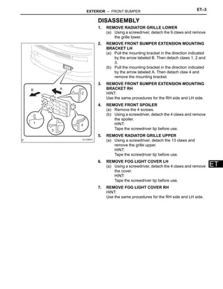
- 1. EXTERIOR – FRONT BUMPER ET–3 ET DISASSEMBLY 1. REMOVE RADIATOR GRILLE LOWER (a) Using a screwdriver, detach the 9 claws and remove the grille lower. 2. REMOVE FRONT BUMPER EXTENSION MOUNTING BRACKET LH (a) Pull the mounting bracket in the direction indicated by the arrow labeled B. Then detach claws 1, 2 and 3. (b) Pull the mounting bracket in the direction indicated by the arrow labeled A. Then detach claw 4 and remove the mounting bracket. 3. REMOVE FRONT BUMPER EXTENSION MOUNTING BRACKET RH HINT: Use the same procedures for the RH side and LH side. 4. REMOVE FRONT SPOILER (a) Remove the 4 screws. (b) Using a screwdriver, detach the 4 claws and remove the spoiler. HINT: Tape the screwdriver tip before use. 5. REMOVE RADIATOR GRILLE UPPER (a) Using a screwdriver, detach the 13 claws and remove the grille upper. HINT: Tape the screwdriver tip before use. 6. REMOVE FOG LIGHT COVER LH (a) Using a screwdriver, detach the 4 claws and remove the cover. HINT: Tape the screwdriver tip before use. 7. REMOVE FOG LIGHT COVER RH HINT: Use the same procedures for the RH side and LH side. A B 1 2 3 4 B121098E01
- 2. ET–4 EXTERIOR – FRONT BUMPER ET REASSEMBLY 1. INSTALL FOG LIGHT COVER LH (a) Attach the 4 claws to install the cover. 2. INSTALL FOG LIGHT COVER RH (a) Attach the 4 claws to install the cover. 3. INSTALL RADIATOR GRILLE UPPER (a) Attach the 13 claws to install the grille upper. 4. INSTALL FRONT SPOILER (a) Attach the 4 claws to install the spoiler. (b) Install the 4 screws. 5. INSTALL FRONT BUMPER EXTENSION MOUNTING BRACKET LH (a) Attach the 4 claws to install the mounting bracket. 6. INSTALL FRONT BUMPER EXTENSION MOUNTING BRACKET RH HINT: Use the same procedures for the RH side and LH side. 7. INSTALL RADIATOR GRILLE LOWER (a) Attach the 9 claws to install the grille lower. B121098E02
- 3. EXTERIOR – FRONT BUMPER ET–5 ET INSTALLATION HINT: A bolt without a torque specification is shown in the standard bolt chart (see page SS-2). 1. INSTALL FRONT BUMPER REINFORCEMENT (a) Install the reinforcement with the 4 nuts. 2. INSTALL FRONT BUMPER COVER (a) Put protective tape under the front fender. (b) Attach the 2 claws to install the bumper cover. (c) Install the 4 bolts, 6 screws and clip. 3. INSTALL FRONT FENDER LINER LH (a) Install the fender liner with the 2 screws. 4. INSTALL FRONT FENDER LINER RH (a) Install the fender liner with the 2 screws. 5. INSTALL RADIATOR GRILLE (a) Install the radiator grille with the 3 clips. Protective Tape B121099E01 B070128E01
- 4. ET–8 EXTERIOR – REAR BUMPER ET DISASSEMBLY 1. REMOVE REAR BUMPER PROTECTOR LH (a) Using a clip remover, remove the 3 clips and bumper protector. 2. REMOVE REAR BUMPER PROTECTOR RH (a) Using a clip remover, remove the 3 clips and bumper protector. 3. REMOVE REAR BUMPER PIECE LH (a) Using a clip remover, remove the 5 clips. (b) Using a screwdriver, detach the 8 claws and remove the bumper piece LH (with bumper piece RH). HINT: Tape the screwdriver tip before use. 4. REMOVE REAR BUMPER PIECE RH (a) Using a clip remover, remove the clip. (b) Using a screwdriver, detach the claws and remove the bumper piece LH from the bumper piece RH. HINT: Tape the screwdriver tip before use. 5. REMOVE REAR BUMPER EXTENSION RH (a) Using a screwdriver, detach the 2 claws and remove the extension. HINT: Tape the screwdriver tip before use. 6. REMOVE REAR SIDE MARKER LIGHT ASSEMBLY LH (a) Remove the nut and marker light. 7. REMOVE REAR SIDE MARKER LIGHT ASSEMBLY RH (a) Remove the nut and marker light.
- 5. EXTERIOR – REAR BUMPER ET–9 ET REASSEMBLY 1. INSTALL REAR SIDE MARKER LIGHT ASSEMBLY LH (a) Install the marker light with the nut. 2. INSTALL REAR SIDE MARKER LIGHT ASSEMBLY RH (a) Install the marker light with the nut. 3. INSTALL REAR BUMPER EXTENSION RH (a) Attach the 2 claws to install the extension. 4. INSTALL REAR BUMPER PIECE RH (a) Attach the claw and install the bumper piece LH to the bumper piece RH with the clip. 5. INSTALL REAR BUMPER PIECE LH (a) Attach the 8 claws and install the bumper piece LH (with bumper piece RH) with the 5 clips. 6. INSTALL REAR BUMPER PROTECTOR LH (a) Install the bumper protector with the 3 clips. 7. INSTALL REAR BUMPER PROTECTOR RH (a) Install the bumper protector with the 3 clips.
- 6. EXTERIOR – FRONT BUMPER ET–1 ET BODY EXTERIOR FRONT BUMPER COMPONENTS FOG LIGHT COVER LH FOG LIGHT COVER RH FRONT BUMPER COVER FRONT BUMPER EXTENSION MOUNTING BRACKET LH FRONT BUMPER EXTENSION MOUNTING BRACKET RH FRONT BUMPER REINFORCEMENT FRONT SPOILER RADIATOR GRILLE RADIATOR GRILLE LOWER RADIATOR GRILLE UPPER B121086E02
- 7. ET–2 EXTERIOR – FRONT BUMPER ET REMOVAL 1. REMOVE RADIATOR GRILLE (a) Using a clip remover, remove the 3 clips and radiator grille. 2. REMOVE FRONT FENDER LINER LH (a) Remove the 2 screws. (b) Partially remove the fender liner. HINT: It is not necessary to fully remove the fender liner. Partially remove it so that the bumper cover can be removed in a later step. 3. REMOVE FRONT FENDER LINER RH HINT: Use the same procedures for the RH side and LH side. 4. REMOVE FRONT BUMPER COVER (a) Put protective tape under the front fender. (b) Remove the clip and 2 bolts from the upper side of the bumper cover. (c) Using a screwdriver, detach the 2 claws and remove the 2 bolts, 6 screws and bumper cover. HINT: Tape the screwdriver tip before use. 5. REMOVE FRONT BUMPER REINFORCEMENT (a) Remove the 4 nuts and reinforcement. B070128E01 Protective Tape B121099E01
- 8. ET–10 EXTERIOR – REAR BUMPER ET INSTALLATION HINT: A bolt without a torque specification is shown in the standard bolt chart (see page SS-2). 1. INSTALL REAR BUMPER SIDE RETAINER LH (a) Install the 2 side retainers with the 2 screws. 2. INSTALL REAR BUMPER SIDE RETAINER RH (a) Install the 2 side retainers with the 2 screws. 3. INSTALL REAR BUMPER REINFORCEMENT SUB- ASSEMBLY (a) Install the reinforcement with the 6 nuts. 4. INSTALL REAR BUMPER SHIELD BRACKET CENTER (a) Attach the 8 claws to install the 3 shield brackets. 5. INSTALL REAR BUMPER COVER (a) Put protective tape under the quarter panel. (b) Attach the clamps and connect the rear side marker light wire harness's connectors. (c) Connect the wire harness's connector to the vehicle body. (d) Attach the 2 claws and install the bumper cover with the 6 bolts. 6. INSTALL REAR BUMPER SIDE SEAL LH (a) Attach the claw and install the side seal with the screw and 2 clips. 7. INSTALL REAR BUMPER SIDE SEAL RH HINT: Use the same procedures described for the LH side. Protective Tape B121100E01 B124224E01
- 9. EXTERIOR – REAR BUMPER ET–5 ET BODY EXTERIOR REAR BUMPER COMPONENTS REAR BUMPER COVER REAR BUMPER REINFORCEMENT SUB-ASSEMBLY REAR BUMPER SHIELD BRACKET CENTER REAR BUMPER SIDE RETAINER LH REAR BUMPER SIDE RETAINER RH REAR BUMPER SIDE SEAL LH REAR BUMPER SIDE SEAL RH REAR SIDE MARKER LIGHT WIRE HARNESS B121102E01
- 10. ET–6 EXTERIOR – REAR BUMPER ET REMOVAL 1. REMOVE REAR BUMPER SIDE SEAL LH (a) Using a clip remover, remove the 2 clips and screw. (b) Using a screwdriver, detach the claw and remove the side seal. HINT: Tape the screwdriver tip before use. 2. REMOVE REAR BUMPER SIDE SEAL RH HINT: Use the same procedures described for the LH side. REAR BUMPER EXTENSION RH REAR BUMPER PIECE LH REAR BUMPER PIECE RH REAR BUMPER PROTECTOR LH REAR BUMPER PROTECTOR RH REAR SIDE MARKER LIGHT ASSEMBLY LH REAR SIDE MARKER LIGHT ASSEMBLY RH REAR BUMPER COVER B121101E01 B124224E01
- 11. EXTERIOR – REAR BUMPER ET–7 ET 3. REMOVE REAR BUMPER COVER (a) Put protective tape under the quarter panel. (b) Using a screwdriver, detach the 2 claws and remove the 6 bolts and bumper cover. HINT: Tape the screwdriver tip before use. (c) Disconnect the rear side marker light wire harness's connector from the vehicle body. (d) Disconnect the wire harness's connectors and detach the clamps. Then, remove the wire harness. 4. REMOVE REAR BUMPER SHIELD BRACKET CENTER (a) Using a screwdriver, detach the 8 claws and remove the 3 shield brackets. HINT: Tape the screwdriver tip before use. 5. REMOVE REAR BUMPER REINFORCEMENT SUB- ASSEMBLY (a) Remove the 6 nuts and reinforcement. 6. REMOVE REAR BUMPER SIDE RETAINER LH (a) Remove the 2 screws and 2 side retainers. 7. REMOVE REAR BUMPER SIDE RETAINER RH (a) Remove the 2 screws and 2 side retainers. Protective Tape B121100E01
- 12. ET–12 EXTERIOR – NAME PLATE ET INSTALLATION HINT: When installing the name plate, heat the vehicle body and name plate using a heat light. Standard heating temperature NOTICE: Do not heat the vehicle body and name plate excessively. 1. INSTALL NO. 2 BACK DOOR NAME PLATE (a) Clean the vehicle body surface. (1) Using a heat light, heat the vehicle body surface. (2) Remove the double-sided tape from the vehicle body. (3) Wipe off any tape adhesive residue with white gasoline. (b) If reusing the name plate: Clean the name plate. (1) Using a heat light, heat the name plate. (2) Remove the double-sided tape from the name plate. (3) Wipe off any tape adhesive residue with white gasoline. (4) Apply new double-sided tape to the name plate. (c) Install the name plate. (1) Using a heat light, heat the vehicle body and name plate. (2) Remove the peeling paper from the face of the name plate. HINT: After removing the peeling paper, keep the exposed adhesive free from foreign matter. (3) Install the name plate. NOTICE: Install the name plate exactly according to the specifications below. Item Temperature Vehicle body 40 to 60°C (104 to 140°F) Name plate 20 to 30°C (68 to 86°F)
- 13. EXTERIOR – NAME PLATE ET–13 ET Standard measurement A B C B070052E05 Area Measurement A 163.9 mm (6.453 in.) B 164.3 mm (6.468 in.) C 61.7 mm (2.429 in.)
- 14. Thank you very much for your reading. Please Click Here. Then Get COMPLETE MANUAL. NO WAITING NOTE: If there is no response to click on the link above, please download the PDF document first and then click on it.
- 15. ET–10 EXTERIOR – NAME PLATE ET BODY EXTERIOR NAME PLATE COMPONENTS NO. 2 BACK DOOR NAME PLATE A A B121103E01
- 16. EXTERIOR – NAME PLATE ET–11 ET REMOVAL HINT: When removing the name plate, heat the vehicle body and name plate using a heat light. Standard heating temperature NOTICE: Do not heat the vehicle body and name plate excessively. 1. REMOVE NO. 2 BACK DOOR NAME PLATE (a) Put protective tape around the name plate. (b) Insert a piano wire between the vehicle body and name plate. (c) Tie objects that can serve as handles (for example, wooden blocks) to both wire ends. (d) Pull the piano wire and scrape off the double-sided tape that holds the name plate to the vehicle body. NOTICE: • If reusing the name plate, take care not to damage the name plate. • Be careful not to damage the vehicle body. Item Temperature Vehicle body 40 to 60°C (104 to 140°F) Name plate 20 to 30°C (68 to 86°F) Protective Tape B121104E01
- 17. EXTERIOR – FRONT DOOR GLASS WEATHERSTRIP ET–15 ET INSTALLATION HINT: • Use the same procedures for the RH side and LH side. • The procedures listed below are for the LH side. 1. INSTALL FRONT DOOR GLASS WEATHERSTRIP ASSEMBLY OUTER LH (a) Attach the claws to install the weatherstrip as shown in the illustration. 2. INSTALL OUTER REAR VIEW MIRROR SUB- ASSEMBLY LH (See page MI-8) 3. INSTALL FRONT DOOR TRIM BOARD SUB- ASSEMBLY LH (See page ED-18) 4. INSTALL POWER WINDOW REGULATOR MASTER SWITCH ASSEMBLY (See page ED-16) 5. INSTALL DOOR PULL HANDLE (See page ED-18) 6. INSTALL FRONT DOOR LOWER FRAME BRACKET GARNISH LH (See page ED-19) 7. CONNECT CABLE TO NEGATIVE BATTERY TERMINAL B121107