SlideShare a Scribd company logo
1 of 20
Download to read offline
CONTENTS
SECTION 1 GENERAL
Group 1 Safety hints ---------------------------------------------------------------------------------------------------- 1-1
Group 2 Specifications ------------------------------------------------------------------------------------------------ 1-4
Group 3 Periodic replacement ------------------------------------------------------------------------------------- 1-12
SECTION 2 REMOVAL & INSTALLATION OF UNIT
Group 1 Major components ---------------------------------------------------------------------------------------- 2-1
Group 2 Removal and installation of unit ------------------------------------------------------------------- 2-2
SECTION 3 POWER TRAIN SYSTEM
Group 1 Structure and operation --------------------------------------------------------------------------------- 3-1
Group 2 Troubleshooting --------------------------------------------------------------------------------------------- 3-4
Group 3 Disassembly and assembly -------------------------------------------------------------------------- 3-5
SECTION 4 BRAKE SYSTEM
Group 1 Structure and function ----------------------------------------------------------------------------------- 4-1
Group 2 Operational checks and troubleshooting ------------------------------------------------------ 4-5
Group 3 Tests and adjustments ---------------------------------------------------------------------------------- 4-7
SECTION 5 STEERING SYSTEM
Group 1 Structure and function ----------------------------------------------------------------------------------- 5-1
Group 2 Operational checks and troubleshooting ------------------------------------------------------- 5-10
Group 3 Disassembly and assembly -------------------------------------------------------------------------- 5-13
SECTION 6 HYDRAULIC SYSTEM
Group 1 Structure and function ----------------------------------------------------------------------------------- 6-1
Group 2 Operational checks and troubleshooting ------------------------------------------------------- 6-16
Group 3 Disassembly and assembly --------------------------------------------------------------------------- 6-20
SECTION 7 ELECTRICAL SYSTEM
Group 1 Component location -------------------------------------------------------------------------------------- 7-1
Group 2 Electrical circuit ---------------------------------------------------------------------------------------------- 7-2
Group 3 Electric components -------------------------------------------------------------------------------------- 7-3
SECTION 8 MAST
Group 1 Structure -------------------------------------------------------------------------------------------------------- 8-1
Group 2 Operational checks and troubleshooting ------------------------------------------------------- 8-6
Group 3 Adjustment ----------------------------------------------------------------------------------------------------- 8-9
Group 4 Removal and installation -------------------------------------------------------------------------------- 8-12
0-1
FOREWORD
1. STRUCTURE
This service manual has been prepared as an aid to improve the quality of repairs by giving the
serviceman an accurate understanding of the product and by showing him the correct way to perform
repairs and make judgements. Make sure you understand the contents of this manual and use it to
full effect at every opportunity.
This service manual mainly contains the necessary technical information for operations performed in
a service workshop.
For ease of understanding, the manual is divided into the following sections.
SECTION 1 GENERAL
This section gives the general information of the machine and explains the safety hints for
maintenance.
SECTION 2 REMOVAL & INSTALLATION OF UNIT
This section explains the procedures and techniques of removal and installation of each component.
SECTION 3 POWER TRAIN SYSTEM
This section explains the structure of the transmission as well as control valve and drive axle.
SECTION 4 BRAKE SYSTEM
This section explains the brake piping, each component and operation.
SECTION 5 STEERING SYSTEM
This section explains the structure of the steering unit, priority valve, trail axle as well as steering
circuit and operation.
SECTION 6 HYDRAULIC SYSTEM
This section explains the structure of the gear pump, main control valve as well as work equipment
circuit, each component and operation.
SECTION 7 ELECTRICAL SYSTEM
This section explains the electrical circuit and each component.
It serves not only to give an understanding electrical system, but also serves as reference material for
troubleshooting.
SECTION 8 MAST
This section explains the structure of mast, carriage, backrest and forks.
The specifications contained in this service manual are subject to change at any time and without any
advance notice. Contact your HYUNDAI distributor for the latest information.
0-2
Revised edition mark( )
When a manual is revised, an edition mark is
recorded on the bottom outside corner of the
pages.
RRevisions
Revised pages are shown at the list of revised
pages on the between the contents page and
section 1 page.
Symbols
So that the shop manual can be of ample
practical use, important places for safety and
quality are marked with the following symbols.
2. HOW TO READ THE SERVICE MANUAL
Distribution and updating
Any additions, amendments or other changes will
be sent to HYUNDAI distributors.
Get the most up-to-date information before you
start any work.
Filing method
See the page number on the bottom of the
page.
File the pages in correct order.
Following examples shows how to read the
page number.
Example 1
2 - 3
Item number(2. Structure and
Function)
Consecutive page number for
each item.
Additional pages : Additional pages are
indicated by a hyphen(-) and number after the
page number. File as in the example.
1.
2.
3.
Symbol Item Remarks
Special safety precautions are
necessary when performing the
work.
Extra special safety precautions
are necessary when performing
the work because it is under
internal pressure.
Special technical precautions or
other precautions for preserving
standards are necessary when
performing the work.
Safety
Caution
10 - 4
10 - 4 - 1
10 - 4 - 2
10 - 5
Added pages
0-3
3. CONVERSION TABLE
Method of using the Conversion Table
The Conversion Table in this section is provided to enable simple conversion of figures. For details of
the method of using the Conversion Table, see the example given below.
Example
Method of using the Conversion Table to convert from millimeters to inches
Convert 55mm into inches.
Locate the number 50in the vertical column at the left side, take this as , then draw a
horizontal line from .
Locate the number 5in the row across the top, take this as , then draw a perpendicular line
down from .
Take the point where the two lines cross as . This point gives the value when converting
from millimeters to inches. Therefore, 55mm = 2.165 inches.
Convert 550mm into inches.
The number 550 does not appear in the table, so divide by 10(Move the decimal point one place
to the left) to convert it to 55mm.
Carry out the same procedure as above to convert 55mm to 2.165 inches.
The original value(550mm) was divided by 10, so multiply 2.165 inches by 10(Move the decimal
point one place to the right) to return to the original value.
This gives 550mm = 21.65 inches.
1.
2.
(1)
(2)
(3)
(1)
(2)
(3)
Millimeters to inches 1mm = 0.03937 in
0 1 2 3 4 5 6 7 8 9
0 0.039 0.079 0.118 0.157 0.197 0.236 0.276 0.315 0.354
10 0.394 0.433 0.472 0.512 0.551 0.591 0.630 0.669 0.709 0.748
20 0.787 0.827 0.866 0.906 0.945 0.984 1.024 1.063 1.102 1.142
30 1.181 1.220 1.260 1.299 1.339 1.378 1.417 1.457 1.496 1.536
40 1.575 1.614 1.654 1.693 1.732 1.772 1.811 1.850 1.890 1.929
50 1.969 2.008 2.047 2.087 2.126 2.165 2.205 2.244 2.283 2.323
60 2.362 2.402 2.441 2.480 2.520 2.559 2.598 2.638 2.677 2.717
70 2.756 2.795 2.835 2.874 2.913 2.953 2.992 3.032 3.071 3.110
80 3.150 3.189 3.228 3.268 3.307 3.346 3.386 3.425 3.465 3.504
90 3.543 3.583 3.622 3.661 3.701 3.740 3.780 3.819 3.858 3.898
0-4
Millimeters to inches 1mm = 0.03937in
0 1 2 3 4 5 6 7 8 9
0 0.039 0.079 0.118 0.157 0.197 0.236 0.276 0.315 0.354
10 0.394 0.433 0.472 0.512 0.551 0.591 0.630 0.669 0.709 0.748
20 0.787 0.827 0.866 0.906 0.945 0.984 1.024 1.063 1.102 1.142
30 1.181 1.220 1.260 1.299 1.339 1.378 1.417 1.457 1.496 1.536
40 1.575 1.614 1.654 1.693 1.732 1.772 1.811 1.850 1.890 1.929
50 1.969 2.008 2.047 2.087 2.126 2.165 2.205 2.244 2.283 2.323
60 2.362 2.402 2.441 2.480 2.520 2.559 2.598 2.638 2.677 2.717
70 2.756 2.795 2.835 2.874 2.913 2.953 2.992 3.032 3.071 3.110
80 3.150 3.189 3.228 3.268 3.307 3.346 3.386 3.425 3.465 3.504
90 3.543 3.583 3.622 3.661 3.701 3.740 3.780 3.819 3.858 3.898
Kilogram to Pound 1kg = 2.2046lb
0 1 2 3 4 5 6 7 8 9
0 2.20 4.41 6.61 8.82 11.02 13.23 15.43 17.64 19.84
10 22.05 24.25 26.46 28.66 30.86 33.07 35.27 37.48 39.68 41.89
20 44.09 46.30 48.50 50.71 51.91 55.12 57.32 59.5. 61.73 63.93
30 66.14 68.34 70.55 72.75 74.96 77.16 79.37 81.57 83.78 85.98
40 88.18 90.39 92.59 94.80 97.00 99.21 101.41 103.62 105.82 108.03
50 110.23 112.44 114.64 116.85 119.05 121.25 123.46 125.66 127.87 130.07
60 132.28 134.48 136.69 138.89 141.10 143.30 145.51 147.71 149.91 152.12
70 154.32 156.53 158.73 160.94 163.14 165.35 167.55 169.76 171.96 174.17
80 176.37 178.57 180.78 182.98 185.19 187.39 189.60 191.80 194.01 196.21
90 198.42 200.62 202.83 205.03 207.24 209.44 211.64 213.85 216.05 218.26
0-5
Liter to U.S. Gallon 1 = 0.2642 U.S.Gal
0 1 2 3 4 5 6 7 8 9
0 0.264 0.528 0.793 1.057 1.321 1.585 1.849 2.113 2.378
10 2.642 2.906 3.170 3.434 3.698 3.963 4.227 4.491 4.755 5.019
20 5.283 5.548 5.812 6.6076 6.340 6.604 6.869 7.133 7.397 7.661
30 7.925 8.189 8.454 8.718 8.982 9.246 9.510 9.774 10.039 10.303
40 10.567 10.831 11.095 11.359 11.624 11.888 12.152 12.416 12.680 12.944
50 13.209 13.473 13.737 14.001 14.265 14.529 14.795 15.058 15.322 15.586
60 15.850 16.115 16.379 16.643 16.907 17.171 17.435 17.700 17.964 18.228
70 18.492 18.756 19.020 19.285 19.549 19.813 20.077 20.341 20.605 20.870
80 21.134 21.398 21.662 21.926 22.190 22.455 22.719 22.983 23.247 23.511
90 23.775 24.040 24.304 24.568 24.832 25.096 25.631 25.625 25.889 26.153
Liter to U.K. Gallon 1 = 0.21997 U.K.Gal
0 1 2 3 4 5 6 7 8 9
0 0.220 0.440 0.660 0.880 1.100 1.320 1.540 1.760 1.980
10 2.200 2.420 2.640 2.860 3.080 3.300 3.520 3.740 3.950 4.179
20 4.399 4.619 4.839 5.059 5.279 5.499 5.719 5.939 6.159 6.379
30 6.599 6.819 7.039 7.259 7.479 7.969 7.919 8.139 8.359 8.579
40 8.799 9.019 9.239 9.459 9.679 9.899 10.119 10.339 10.559 10.778
50 10.998 11.281 11.438 11.658 11.878 12.098 12.318 12.528 12.758 12.978
60 13.198 13.418 13.638 13.858 14.078 14.298 14.518 14.738 14.958 15.178
70 15.398 15.618 15.838 16.058 16.278 16.498 16.718 16.938 17.158 17.378
80 17.598 17.818 18.037 18.257 18.477 18.697 18.917 19.137 19.357 19.577
90 19.797 20.017 20.237 20.457 20.677 20.897 21.117 21.337 21.557 21.777
0-6
kgf m to lbf ft 1kgf m = 7.233lbf ft
0 1 2 3 4 5 6 7 8 9
7.2 14.5 21.7 28.9 36.2 43.4 50.6 57.9 65.1
10 72.3 79.6 86.8 94.0 101.3 108.5 115.7 123.0 130.2 137.4
20 144.7 151.9 159.1 166.4 173.6 180.8 188.1 195.3 202.5 209.8
30 217.0 224.2 231.5 238.7 245.9 253.2 260.4 267.6 274.9 282.1
40 289.3 396.6 303.8 311.0 318.3 325.5 332.7 340.0 347.2 354.4
50 361.7 368.9 376.1 383.4 390.6 397.8 405.1 412.3 419.5 426.8
60 434.0 441.2 448.5 455.7 462.9 470.2 477.4 484.6 491.8 499.1
70 506.3 513.5 520.8 528.0 535.2 542.5 549.7 556.9 564.2 571.4
80 578.6 585.9 593.1 600.3 607.6 614.8 622.0 629.3 636.5 643.7
90 651.0 658.2 665.4 672.7 679.9 687.1 694.4 701.6 708.8 716.1
100 723.3 730.5 737.8 745.0 752.2 759.5 766.7 773.9 781.2 788.4
110 795.6 802.9 810.1 817.3 824.6 831.8 839.0 846.3 853.5 860.7
120 868.0 875.2 882.4 889.7 896.9 904.1 911.4 918.6 925.8 933.1
130 940.3 947.5 954.8 962.0 969.2 976.5 983.7 990.9 998.2 10005.4
140 1012.6 1019.9 1027.1 1034.3 1041.5 1048.8 1056.0 1063.2 1070.5 1077.7
150 1084.9 1092.2 1099.4 1106.6 1113.9 1121.1 1128.3 1135.6 1142.8 1150.0
160 1157.3 1164.5 1171.7 1179.0 1186.2 1193.4 1200.7 1207.9 1215.1 1222.4
170 1129.6 1236.8 1244.1 1251.3 1258.5 1265.8 1273.0 1280.1 1287.5 1294.7
180 1301.9 1309.2 1316.4 1323.6 1330.9 1338.1 1345.3 1352.6 1359.8 1367.0
190 1374.3 1381.5 1388.7 1396.0 1403.2 1410.4 1417.7 1424.9 1432.1 1439.4
0-7
kgf/cm2
to lbf/in2
1kgf / cm2
= 14.2233lbf / in2
0 1 2 3 4 5 6 7 8 9
14.2 28.4 42.7 56.9 71.1 85.3 99.6 113.8 128.0
10 142.2 156.5 170.7 184.9 199.1 213.4 227.6 241.8 256.0 270.2
20 284.5 298.7 312.9 327.1 341.4 355.6 369.8 384.0 398.3 412.5
30 426.7 440.9 455.1 469.4 483.6 497.8 512.0 526.3 540.5 554.7
40 568.9 583.2 597.4 611.6 625.8 640.1 654.3 668.5 682.7 696.9
50 711.2 725.4 739.6 753.8 768.1 782.3 796.5 810.7 825.0 839.2
60 853.4 867.6 881.8 896.1 910.3 924.5 938.7 953.0 967.2 981.4
70 995.6 1010 1024 1038 1053 1067 1081 1095 1109 1124
80 1138 1152 1166 1181 1195 1209 1223 1237 1252 1266
90 1280 1294 1309 1323 1337 1351 1365 1380 1394 1408
100 1422 1437 1451 1465 1479 1493 1508 1522 1536 1550
110 1565 1579 1593 1607 1621 1636 1650 1664 1678 1693
120 1707 1721 1735 1749 1764 1778 1792 1806 1821 1835
130 1849 2863 1877 1892 1906 1920 1934 1949 1963 1977
140 1991 2005 2020 2034 2048 2062 2077 2091 2105 2119
150 2134 2148 2162 2176 2190 2205 2219 2233 2247 2262
160 2276 2290 2304 2318 2333 2347 2361 2375 2389 2404
170 2418 2432 2446 2460 2475 2489 2503 2518 2532 2546
180 2560 2574 2589 5603 2617 2631 2646 2660 2674 2688
200 2845 2859 2873 2887 2901 2916 2930 2944 2958 2973
210 2987 3001 3015 3030 3044 3058 3072 3086 3101 3115
220 3129 3143 3158 3172 3186 3200 3214 3229 3243 3257
230 3271 3286 3300 3314 3328 3343 3357 3371 3385 3399
240 3414 3428 3442 3456 3470 3485 3499 3513 3527 3542
TEMPERATURE
Fahrenheit-Centigrade Conversion.
A simple way to convert a fahrenheit temperature reading into a centigrade temperature reading or vice verse
is to enter the accompanying table in the center or boldface column of figures.
These figures refer to the temperature in either Fahrenheit or Centigrade degrees.
If it is desired to convert from Fahrenheit to Centigrade degrees, consider the center column as a table of
Fahrenheit temperatures and read the corresponding Centigrade temperature in the column at the left.
If it is desired to convert from Centigrade to Fahrenheit degrees, consider the center column as a table of
Centigrade values, and read the corresponding Fahrenheit temperature on the right.
0-8
C F C F C F C F
-40.4 -40 -40.0 -11.7 11 51.8 7.8 46 114.8 27.2 81 117.8
-37.2 -35 -31.0 -11.1 12 53.6 8.3 47 116.6 27.8 82 179.6
-34.4 -30 -22.0 -10.6 13 55.4 8.9 48 118.4 28.3 83 181.4
-31.7 -25 -13.0 -10.0 14 57.2 9.4 49 120.2 28.9 84 183.2
-28.9 -20 -4.0 -9.4 15 59.0 10.0 50 122.0 29.4 85 185.0
-28.3 -19 -2.2 -8.9 16 60.8 10.6 51 123.8 30.0 86 186.8
-27.8 -18 -0.4 -8.3 17 62.6 11.1 52 125.6 30.6 87 188.6
-27.2 -17 1.4 -7.8 18 64.4 11.7 53 127.4 31.1 88 190.4
-26.7 -16 3.2 -6.7 20 68.0 12.8 55 131.0 32.2 90 194.0
-26.1 -15 5.0 -6.7 20 68.0 12.8 55 131.0 32.2 90 194.0
-25.6 -14 6.8 -6.1 21 69.8 13.3 56 132.8 32.8 91 195.8
-25.0 -13 8.6 -5.6 22 71.6 13.9 57 134.6 33.3 92 197.6
-24.4 -12 10.4 -5.0 23 73.4 14.4 58 136.4 33.9 93 199.4
-23.9 -11 12.2 -4.4 24 75.2 15.0 59 138.2 34.4 94 201.2
-23.3 -10 14.0 -3.9 25 77.0 15.6 60 140.0 35.0 95 203.0
-22.8 -9 15.8 -3.3 26 78.8 16.1 61 141.8 35.6 96 204.8
-22.2 -8 17.6 -2.8 27 80.6 16.7 62 143.6 36.1 97 206.6
-21.7 -7 19.4 -2.2 28 82.4 17.2 63 145.4 36.7 98 208.4
-21.1 -6 21.2 -1.7 29 84.2 17.8 64 147.2 37.2 99 210.2
-20.6 -5 23.0 -1.1 35 95.0 21.1 70 158.0 51.7 125 257.0
-20.0 -4 24.8 -0.6 31 87.8 18.9 66 150.8 40.6 105 221.0
-19.4 -3 26.6 0 32 89.6 19.4 67 152.6 43.3 110 230.0
-18.9 -2 28.4 0.6 33 91.4 20.0 68 154.4 46.1 115 239.0
-18.3 -1 30.2 1.1 34 93.2 20.6 69 156.2 48.9 120 248.0
-17.8 0 32.0 1.7 35 95.0 21.1 70 158.0 51.7 125 257.0
-17.2 1 33.8 2.2 36 96.8 21.7 71 159.8 54.4 130 266.0
-16.7 2 35.6 2.8 37 98.6 22.2 72 161.6 57.2 135 275.0
-16.1 3 37.4 3.3 38 100.4 22.8 73 163.4 60.0 140 284.0
-15.6 4 39.2 3.9 39 102.2 23.3 74 165.2 62.7 145 293.0
-15.0 5 41.0 4.4 40 104.0 23.9 75 167.0 65.6 150 302.0
-14.4 6 42.8 5.0 41 105.8 24.4 76 168.8 68.3 155 311.0
-13.9 7 44.6 5.6 42 107.6 25.0 77 170.6 71.1 160 320.0
-13.3 8 46.4 6.1 43 109.4 25.6 78 172.4 73.9 165 329.0
-12.8 9 48.2 6.7 44 111.2 26.1 79 174.2 76.7 170 338.0
-12.2 10 50.0 7.2 45 113.0 26.7 80 176.0 79.4 172 347.0
5-13
GROUP 3 DISASSEMBLY AND ASSEMBLY
1. STEERING UNIT
STRUCTURE1)
1
27-2
5
15
6
8
2
18
11
3
22
21
23
27-4
27-3
27-1
4
13
14
24
24
29-5
29-6
29-4
29-3
29-1
29-2
20
17
9
12
7
10
19
16
13
10
10
22B7SS08
1 Dust seal
2 Retaining seal
3 Cap seal
4 Thrust bearing
5 Ball
6 Pin
7 Spacer
8 Centering spring
9 Washer
10 O-ring
11 O-ring
12 Rolled screw
13 Gerotor set
14 Bearing race
15 Bore screw
16 Drive
17 End cap
18 Gland bushing
19 Plate
20 Cap screw
21 Housing
22 Spool
23 Sleeve
24 Plate spring
27 P-port check valve
27-1 Plug
27-2 Poppet
27-3 Spring seat
27-4 Spring
29 Relief valve
29-1 Spool
29-2 Bushing
29-3 Spring
29-4 Spring seat
29-5 Plug
29-6 O-ring
5-14
TOOLS
Holding tool.
2)
(1)
Assembly tool for O-ring and kin-ring.(2)
Assembly tool for lip seal.(3)
Assembly tool for cardan shaft.(4)
5-69(1)
5-69(2)
5-69(3)
5-69(4)
5-15
Assembly tool for dust seal.(5)
Torque wrench 0~7.1kgf m
(0~54.4lbf ft)
13mm socket spanner
6, 8mm and 12mm hexagon sockets
12mm screwdriver
2mm screwdriver
13mm ring spanner
6, 8 and 12mm hexagon socket spanners
Plastic hammer
Tweezers
(6)
5-70(1)
5-70(2)
D353SE23
TIGHTENING TORQUE
L : Left port
R : Right port
T : Tank
P : Pump
3)
Port
L
R
T
P
Mounting bolt
Size
3/4 UNF - 16
3/4 UNF - 16
3/4 UNF - 16
3/4 UNF - 16
M10 1.5
Torque [kgf m(lbf ft)]
6.1 0.6 (44.1 4.3)
6.1 0.6 (44.1 4.3)
6.1 0.6 (44.1 4.3)
6.1 0.6 (44.1 4.3)
4.0 0.5 (29 3.6)
5-16
DISASSEMBLY
Disassemble steering column from
steering unit and place the steering unit in
the holding tool.
Screw out the screws in the end cover(6-
off plus one special screw).
4)
(1)
Remove the end cover, sideways.(2)
Lift the gearwheel set(With spacer if fitted)
off the unit.
Take out the two O-rings.
(3)
Remove cardan shaft.(4)
5-72(1)
5-72(2)
5-72(3)
5-72(4)
5-17
Remove distributor plate.(5)
Screw out the threaded bush over the
check valve.
(6)
Remove O-ring.(7)
Shake out the check valve ball.(8)
5-73(1)
5-73(2)
5-73(3)
B20H7SS09
5-18
Take ring, bearing races and thrust
bearing from sleeve and spool. The outer
(Thin) bearing race can sometimes "stick"
in the housing, therefore check that it has
come out.
(10)
Press out the cross pin. Use the special
screw from the end cover.
(11)
A small mark has been made with a
pumice stone on both spool and sleeve
close to one of the slots for the neutral
position springs(See drawing).
If the mark is not visible, remember to
leave a mark of your own on sleeve and
spool before the neutral position springs
are disassembled.
Take care to keep the cross pin in the
sleeve and spool horizontal. The pin can
be seen through the open end of the
spool. Press the spool inwards and the
sleeve, ring, bearing races and thrust
bearing will be pushed out of the housing
together.
(9)
5-73(4)
5-74(1)
5-74(2)
5-74(3)
5-19
Press the neutral position springs out of
their slots in the spool.
(13)
Remove dust seal and O-ring.(14)
Disassembling the pressure relief valve
Screw out the plug using an 8mm hexagon
socket spanner.
Remove seal washers.
(15)
Carefully press the spool out of the sleeve.(12)
5-74(4)
5-75(1)
5-75(2)
D353SE10
5-20
Unscrew the setting screw using an 8mm
hexagon socket spanner.
(16)
Shake out spring and piston. The valve
seat is bonded into the housing and cannot
be removed.
(17)
The pressure relief valve is now disassem-
bled.
(18)
D353SE11
D353SE12
D353SE13
Thank you very much for
your reading. Please Click
Here. Then Get COMPLETE
MANUAL. NO WAITING
NOTE:
If there is no response to
click on the link above,
please download the PDF
document first and then
click on it.
5-21
ASSEMBLY
Assemble spool and sleeve.
When assembling spool and sleeve only
one of two possible ways of positioning
the spring slots is correct. There are
three slots in the spool and three holes in
the sleeve in the end of the spool / sleeve
opposite to the end with spring slots.
Place the slots and holes opposite each
other so that parts of the holes in the
sleeve are visible through the slots in the
spool.
5)
(1)
Place the two flat neutral position springs
in the slot.
Place the curved springs between the flat
ones and press them into place (see
assembly pattern).
(2)
Line up the spring set.(3)
5-76(1)
5-76(2)
5-76(4)
Guide the spool into the sleeve. Make
sure that spool and sleeve are placed
correctly in relation to each other.
(4)
5-77(1)
5-22
Press the springs together and push the
neutral position springs into place in the
sleeve.
(5)
Line up the springs and center them.(6)
Guide the ring down over the sleeve.
The ring should be able to rotate free of
the springs.
(7)
5-77(2)
5-77(3)
5-77(4)
Fit the cross pin into the spool / sleeve.(8)
5-78(1)

More Related Content

Similar to Maintenance Manual Sections Guide

Hyundai 50 da 7e forklift truck service repair manual
Hyundai 50 da 7e forklift truck service repair manualHyundai 50 da 7e forklift truck service repair manual
Hyundai 50 da 7e forklift truck service repair manualfusjejkdkmse
 
Hyundai 40 ds 7e forklift truck service repair manual
Hyundai 40 ds 7e forklift truck service repair manualHyundai 40 ds 7e forklift truck service repair manual
Hyundai 40 ds 7e forklift truck service repair manualfjjsekmsmmes
 
Hyundai 35 ds 7e forklift truck service repair manual
Hyundai 35 ds 7e forklift truck service repair manualHyundai 35 ds 7e forklift truck service repair manual
Hyundai 35 ds 7e forklift truck service repair manualfjjsekmsmmes
 
Hyundai 50 da 7e forklift truck service repair manual
Hyundai 50 da 7e forklift truck service repair manualHyundai 50 da 7e forklift truck service repair manual
Hyundai 50 da 7e forklift truck service repair manualfjkskekxsdcmdmme
 
Hyundai 40 ds 7e forklift truck service repair manual
Hyundai 40 ds 7e forklift truck service repair manualHyundai 40 ds 7e forklift truck service repair manual
Hyundai 40 ds 7e forklift truck service repair manualfjjskekdmmme
 
Hyundai 45 ds 7e forklift truck service repair manual
Hyundai 45 ds 7e forklift truck service repair manualHyundai 45 ds 7e forklift truck service repair manual
Hyundai 45 ds 7e forklift truck service repair manualfjkskekxsdcmdmme
 

Similar to Maintenance Manual Sections Guide (6)

Hyundai 50 da 7e forklift truck service repair manual
Hyundai 50 da 7e forklift truck service repair manualHyundai 50 da 7e forklift truck service repair manual
Hyundai 50 da 7e forklift truck service repair manual
 
Hyundai 40 ds 7e forklift truck service repair manual
Hyundai 40 ds 7e forklift truck service repair manualHyundai 40 ds 7e forklift truck service repair manual
Hyundai 40 ds 7e forklift truck service repair manual
 
Hyundai 35 ds 7e forklift truck service repair manual
Hyundai 35 ds 7e forklift truck service repair manualHyundai 35 ds 7e forklift truck service repair manual
Hyundai 35 ds 7e forklift truck service repair manual
 
Hyundai 50 da 7e forklift truck service repair manual
Hyundai 50 da 7e forklift truck service repair manualHyundai 50 da 7e forklift truck service repair manual
Hyundai 50 da 7e forklift truck service repair manual
 
Hyundai 40 ds 7e forklift truck service repair manual
Hyundai 40 ds 7e forklift truck service repair manualHyundai 40 ds 7e forklift truck service repair manual
Hyundai 40 ds 7e forklift truck service repair manual
 
Hyundai 45 ds 7e forklift truck service repair manual
Hyundai 45 ds 7e forklift truck service repair manualHyundai 45 ds 7e forklift truck service repair manual
Hyundai 45 ds 7e forklift truck service repair manual
 

More from fjsjekkmdmme

Mc cormick fxl techno tier 3 (2008 2009) - rp54 - f 105 gexl tractor service ...
Mc cormick fxl techno tier 3 (2008 2009) - rp54 - f 105 gexl tractor service ...Mc cormick fxl techno tier 3 (2008 2009) - rp54 - f 105 gexl tractor service ...
Mc cormick fxl techno tier 3 (2008 2009) - rp54 - f 105 gexl tractor service ...fjsjekkmdmme
 
Mc cormick fxl techno tier 3 (2008 2009) - rp54 - f 100 gexl tractor service ...
Mc cormick fxl techno tier 3 (2008 2009) - rp54 - f 100 gexl tractor service ...Mc cormick fxl techno tier 3 (2008 2009) - rp54 - f 100 gexl tractor service ...
Mc cormick fxl techno tier 3 (2008 2009) - rp54 - f 100 gexl tractor service ...fjsjekkmdmme
 
Mc cormick fxl techno tier 3 (2008 2009) - rp54 - f 80 gexl tractor service r...
Mc cormick fxl techno tier 3 (2008 2009) - rp54 - f 80 gexl tractor service r...Mc cormick fxl techno tier 3 (2008 2009) - rp54 - f 80 gexl tractor service r...
Mc cormick fxl techno tier 3 (2008 2009) - rp54 - f 80 gexl tractor service r...fjsjekkmdmme
 
Mc cormick fxl techno tier 3 (2008 2009) - rp54 - f 75 ge tractor service rep...
Mc cormick fxl techno tier 3 (2008 2009) - rp54 - f 75 ge tractor service rep...Mc cormick fxl techno tier 3 (2008 2009) - rp54 - f 75 ge tractor service rep...
Mc cormick fxl techno tier 3 (2008 2009) - rp54 - f 75 ge tractor service rep...fjsjekkmdmme
 
Mc cormick fxl techno tier 2 (2003 2008) - rp52 - f105 fgexl tractor service ...
Mc cormick fxl techno tier 2 (2003 2008) - rp52 - f105 fgexl tractor service ...Mc cormick fxl techno tier 2 (2003 2008) - rp52 - f105 fgexl tractor service ...
Mc cormick fxl techno tier 2 (2003 2008) - rp52 - f105 fgexl tractor service ...fjsjekkmdmme
 
Mc cormick fxl techno tier 2 (2003 2008) - rp52 - f85 fgexl tractor service r...
Mc cormick fxl techno tier 2 (2003 2008) - rp52 - f85 fgexl tractor service r...Mc cormick fxl techno tier 2 (2003 2008) - rp52 - f85 fgexl tractor service r...
Mc cormick fxl techno tier 2 (2003 2008) - rp52 - f85 fgexl tractor service r...fjsjekkmdmme
 
Mc cormick fxl techno tier 2 (2003 2008) - rp52 - f80 fge tractor service rep...
Mc cormick fxl techno tier 2 (2003 2008) - rp52 - f80 fge tractor service rep...Mc cormick fxl techno tier 2 (2003 2008) - rp52 - f80 fge tractor service rep...
Mc cormick fxl techno tier 2 (2003 2008) - rp52 - f80 fge tractor service rep...fjsjekkmdmme
 
Mc cormick fxl techno tier 2 (2003 2008) - rp52 - f75 fgexl tractor service r...
Mc cormick fxl techno tier 2 (2003 2008) - rp52 - f75 fgexl tractor service r...Mc cormick fxl techno tier 2 (2003 2008) - rp52 - f75 fgexl tractor service r...
Mc cormick fxl techno tier 2 (2003 2008) - rp52 - f75 fgexl tractor service r...fjsjekkmdmme
 
Mc cormick fxl techno tier 2 (2003 2008) - rp52 - f70 fge tractor service rep...
Mc cormick fxl techno tier 2 (2003 2008) - rp52 - f70 fge tractor service rep...Mc cormick fxl techno tier 2 (2003 2008) - rp52 - f70 fge tractor service rep...
Mc cormick fxl techno tier 2 (2003 2008) - rp52 - f70 fge tractor service rep...fjsjekkmdmme
 
Mc cormick f top restyling (2010 ) - rp55 - f100gexl tractor service repair ...
Mc cormick f top restyling (2010  ) - rp55 - f100gexl tractor service repair ...Mc cormick f top restyling (2010  ) - rp55 - f100gexl tractor service repair ...
Mc cormick f top restyling (2010 ) - rp55 - f100gexl tractor service repair ...fjsjekkmdmme
 
Komatsu h185 s hydraulic shovel service repair manual (sn 6111)
Komatsu h185 s hydraulic shovel service repair manual (sn 6111)Komatsu h185 s hydraulic shovel service repair manual (sn 6111)
Komatsu h185 s hydraulic shovel service repair manual (sn 6111)fjsjekkmdmme
 
Komatsu d575 a 2 dozer bulldozer service repair manual (sn 10001 and up)
Komatsu d575 a 2 dozer bulldozer service repair manual (sn 10001 and up)Komatsu d575 a 2 dozer bulldozer service repair manual (sn 10001 and up)
Komatsu d575 a 2 dozer bulldozer service repair manual (sn 10001 and up)fjsjekkmdmme
 
Komatsu d475 a 2 dozer bulldozer service repair manual (sn 10201 and up)
Komatsu d475 a 2 dozer bulldozer service repair manual (sn 10201 and up)Komatsu d475 a 2 dozer bulldozer service repair manual (sn 10201 and up)
Komatsu d475 a 2 dozer bulldozer service repair manual (sn 10201 and up)fjsjekkmdmme
 
Komatsu d65 wx 16 dozer bulldozer service repair manual sn 80001 and up
Komatsu d65 wx 16 dozer bulldozer service repair manual sn 80001 and upKomatsu d65 wx 16 dozer bulldozer service repair manual sn 80001 and up
Komatsu d65 wx 16 dozer bulldozer service repair manual sn 80001 and upfjsjekkmdmme
 
Komatsu d65 wx 15e0 dozer bulldozer service repair manual sn 69001 and up
Komatsu d65 wx 15e0 dozer bulldozer service repair manual sn 69001 and upKomatsu d65 wx 15e0 dozer bulldozer service repair manual sn 69001 and up
Komatsu d65 wx 15e0 dozer bulldozer service repair manual sn 69001 and upfjsjekkmdmme
 
Komatsu d65 px 16 dozer bulldozer service repair manual sn 80001 and up
Komatsu d65 px 16 dozer bulldozer service repair manual sn 80001 and upKomatsu d65 px 16 dozer bulldozer service repair manual sn 80001 and up
Komatsu d65 px 16 dozer bulldozer service repair manual sn 80001 and upfjsjekkmdmme
 
Komatsu d65 px 15e0 dozer bulldozer service repair manual sn 69001 and up
Komatsu d65 px 15e0 dozer bulldozer service repair manual sn 69001 and upKomatsu d65 px 15e0 dozer bulldozer service repair manual sn 69001 and up
Komatsu d65 px 15e0 dozer bulldozer service repair manual sn 69001 and upfjsjekkmdmme
 
Komatsu d65 px 12 dozer bulldozer service repair manual sn 65275 and up
Komatsu d65 px 12 dozer bulldozer service repair manual sn 65275 and upKomatsu d65 px 12 dozer bulldozer service repair manual sn 65275 and up
Komatsu d65 px 12 dozer bulldozer service repair manual sn 65275 and upfjsjekkmdmme
 
Komatsu d65 ex 16 dozer bulldozer service repair manual sn 80001 and up
Komatsu d65 ex 16 dozer bulldozer service repair manual sn 80001 and upKomatsu d65 ex 16 dozer bulldozer service repair manual sn 80001 and up
Komatsu d65 ex 16 dozer bulldozer service repair manual sn 80001 and upfjsjekkmdmme
 
Komatsu d65 ex 15e0 dozer bulldozer service repair manual sn 69001 and up
Komatsu d65 ex 15e0 dozer bulldozer service repair manual sn 69001 and upKomatsu d65 ex 15e0 dozer bulldozer service repair manual sn 69001 and up
Komatsu d65 ex 15e0 dozer bulldozer service repair manual sn 69001 and upfjsjekkmdmme
 

More from fjsjekkmdmme (20)

Mc cormick fxl techno tier 3 (2008 2009) - rp54 - f 105 gexl tractor service ...
Mc cormick fxl techno tier 3 (2008 2009) - rp54 - f 105 gexl tractor service ...Mc cormick fxl techno tier 3 (2008 2009) - rp54 - f 105 gexl tractor service ...
Mc cormick fxl techno tier 3 (2008 2009) - rp54 - f 105 gexl tractor service ...
 
Mc cormick fxl techno tier 3 (2008 2009) - rp54 - f 100 gexl tractor service ...
Mc cormick fxl techno tier 3 (2008 2009) - rp54 - f 100 gexl tractor service ...Mc cormick fxl techno tier 3 (2008 2009) - rp54 - f 100 gexl tractor service ...
Mc cormick fxl techno tier 3 (2008 2009) - rp54 - f 100 gexl tractor service ...
 
Mc cormick fxl techno tier 3 (2008 2009) - rp54 - f 80 gexl tractor service r...
Mc cormick fxl techno tier 3 (2008 2009) - rp54 - f 80 gexl tractor service r...Mc cormick fxl techno tier 3 (2008 2009) - rp54 - f 80 gexl tractor service r...
Mc cormick fxl techno tier 3 (2008 2009) - rp54 - f 80 gexl tractor service r...
 
Mc cormick fxl techno tier 3 (2008 2009) - rp54 - f 75 ge tractor service rep...
Mc cormick fxl techno tier 3 (2008 2009) - rp54 - f 75 ge tractor service rep...Mc cormick fxl techno tier 3 (2008 2009) - rp54 - f 75 ge tractor service rep...
Mc cormick fxl techno tier 3 (2008 2009) - rp54 - f 75 ge tractor service rep...
 
Mc cormick fxl techno tier 2 (2003 2008) - rp52 - f105 fgexl tractor service ...
Mc cormick fxl techno tier 2 (2003 2008) - rp52 - f105 fgexl tractor service ...Mc cormick fxl techno tier 2 (2003 2008) - rp52 - f105 fgexl tractor service ...
Mc cormick fxl techno tier 2 (2003 2008) - rp52 - f105 fgexl tractor service ...
 
Mc cormick fxl techno tier 2 (2003 2008) - rp52 - f85 fgexl tractor service r...
Mc cormick fxl techno tier 2 (2003 2008) - rp52 - f85 fgexl tractor service r...Mc cormick fxl techno tier 2 (2003 2008) - rp52 - f85 fgexl tractor service r...
Mc cormick fxl techno tier 2 (2003 2008) - rp52 - f85 fgexl tractor service r...
 
Mc cormick fxl techno tier 2 (2003 2008) - rp52 - f80 fge tractor service rep...
Mc cormick fxl techno tier 2 (2003 2008) - rp52 - f80 fge tractor service rep...Mc cormick fxl techno tier 2 (2003 2008) - rp52 - f80 fge tractor service rep...
Mc cormick fxl techno tier 2 (2003 2008) - rp52 - f80 fge tractor service rep...
 
Mc cormick fxl techno tier 2 (2003 2008) - rp52 - f75 fgexl tractor service r...
Mc cormick fxl techno tier 2 (2003 2008) - rp52 - f75 fgexl tractor service r...Mc cormick fxl techno tier 2 (2003 2008) - rp52 - f75 fgexl tractor service r...
Mc cormick fxl techno tier 2 (2003 2008) - rp52 - f75 fgexl tractor service r...
 
Mc cormick fxl techno tier 2 (2003 2008) - rp52 - f70 fge tractor service rep...
Mc cormick fxl techno tier 2 (2003 2008) - rp52 - f70 fge tractor service rep...Mc cormick fxl techno tier 2 (2003 2008) - rp52 - f70 fge tractor service rep...
Mc cormick fxl techno tier 2 (2003 2008) - rp52 - f70 fge tractor service rep...
 
Mc cormick f top restyling (2010 ) - rp55 - f100gexl tractor service repair ...
Mc cormick f top restyling (2010  ) - rp55 - f100gexl tractor service repair ...Mc cormick f top restyling (2010  ) - rp55 - f100gexl tractor service repair ...
Mc cormick f top restyling (2010 ) - rp55 - f100gexl tractor service repair ...
 
Komatsu h185 s hydraulic shovel service repair manual (sn 6111)
Komatsu h185 s hydraulic shovel service repair manual (sn 6111)Komatsu h185 s hydraulic shovel service repair manual (sn 6111)
Komatsu h185 s hydraulic shovel service repair manual (sn 6111)
 
Komatsu d575 a 2 dozer bulldozer service repair manual (sn 10001 and up)
Komatsu d575 a 2 dozer bulldozer service repair manual (sn 10001 and up)Komatsu d575 a 2 dozer bulldozer service repair manual (sn 10001 and up)
Komatsu d575 a 2 dozer bulldozer service repair manual (sn 10001 and up)
 
Komatsu d475 a 2 dozer bulldozer service repair manual (sn 10201 and up)
Komatsu d475 a 2 dozer bulldozer service repair manual (sn 10201 and up)Komatsu d475 a 2 dozer bulldozer service repair manual (sn 10201 and up)
Komatsu d475 a 2 dozer bulldozer service repair manual (sn 10201 and up)
 
Komatsu d65 wx 16 dozer bulldozer service repair manual sn 80001 and up
Komatsu d65 wx 16 dozer bulldozer service repair manual sn 80001 and upKomatsu d65 wx 16 dozer bulldozer service repair manual sn 80001 and up
Komatsu d65 wx 16 dozer bulldozer service repair manual sn 80001 and up
 
Komatsu d65 wx 15e0 dozer bulldozer service repair manual sn 69001 and up
Komatsu d65 wx 15e0 dozer bulldozer service repair manual sn 69001 and upKomatsu d65 wx 15e0 dozer bulldozer service repair manual sn 69001 and up
Komatsu d65 wx 15e0 dozer bulldozer service repair manual sn 69001 and up
 
Komatsu d65 px 16 dozer bulldozer service repair manual sn 80001 and up
Komatsu d65 px 16 dozer bulldozer service repair manual sn 80001 and upKomatsu d65 px 16 dozer bulldozer service repair manual sn 80001 and up
Komatsu d65 px 16 dozer bulldozer service repair manual sn 80001 and up
 
Komatsu d65 px 15e0 dozer bulldozer service repair manual sn 69001 and up
Komatsu d65 px 15e0 dozer bulldozer service repair manual sn 69001 and upKomatsu d65 px 15e0 dozer bulldozer service repair manual sn 69001 and up
Komatsu d65 px 15e0 dozer bulldozer service repair manual sn 69001 and up
 
Komatsu d65 px 12 dozer bulldozer service repair manual sn 65275 and up
Komatsu d65 px 12 dozer bulldozer service repair manual sn 65275 and upKomatsu d65 px 12 dozer bulldozer service repair manual sn 65275 and up
Komatsu d65 px 12 dozer bulldozer service repair manual sn 65275 and up
 
Komatsu d65 ex 16 dozer bulldozer service repair manual sn 80001 and up
Komatsu d65 ex 16 dozer bulldozer service repair manual sn 80001 and upKomatsu d65 ex 16 dozer bulldozer service repair manual sn 80001 and up
Komatsu d65 ex 16 dozer bulldozer service repair manual sn 80001 and up
 
Komatsu d65 ex 15e0 dozer bulldozer service repair manual sn 69001 and up
Komatsu d65 ex 15e0 dozer bulldozer service repair manual sn 69001 and upKomatsu d65 ex 15e0 dozer bulldozer service repair manual sn 69001 and up
Komatsu d65 ex 15e0 dozer bulldozer service repair manual sn 69001 and up
 

Recently uploaded

BLUE VEHICLES the kids picture show 2024
BLUE VEHICLES the kids picture show 2024BLUE VEHICLES the kids picture show 2024
BLUE VEHICLES the kids picture show 2024AHOhOops1
 
UNIT-V-ELECTRIC AND HYBRID VEHICLES.pptx
UNIT-V-ELECTRIC AND HYBRID VEHICLES.pptxUNIT-V-ELECTRIC AND HYBRID VEHICLES.pptx
UNIT-V-ELECTRIC AND HYBRID VEHICLES.pptxDineshKumar4165
 
John Deere 200lc Excavator Operation And Tests Repair Manual.pdf
John Deere 200lc Excavator Operation And Tests Repair Manual.pdfJohn Deere 200lc Excavator Operation And Tests Repair Manual.pdf
John Deere 200lc Excavator Operation And Tests Repair Manual.pdfExcavator
 
John Deere Tractors 5515 Diagnostic Repair Manual
John Deere Tractors 5515 Diagnostic Repair ManualJohn Deere Tractors 5515 Diagnostic Repair Manual
John Deere Tractors 5515 Diagnostic Repair ManualExcavator
 
UNIT-II-ENGINE AUXILIARY SYSTEMS &TURBOCHARGER
UNIT-II-ENGINE AUXILIARY SYSTEMS &TURBOCHARGERUNIT-II-ENGINE AUXILIARY SYSTEMS &TURBOCHARGER
UNIT-II-ENGINE AUXILIARY SYSTEMS &TURBOCHARGERDineshKumar4165
 
Vip Hot Call Girls 🫤 Mahipalpur ➡️ 9711199171 ➡️ Delhi 🫦 Whatsapp Number
Vip Hot Call Girls 🫤 Mahipalpur ➡️ 9711199171 ➡️ Delhi 🫦 Whatsapp NumberVip Hot Call Girls 🫤 Mahipalpur ➡️ 9711199171 ➡️ Delhi 🫦 Whatsapp Number
Vip Hot Call Girls 🫤 Mahipalpur ➡️ 9711199171 ➡️ Delhi 🫦 Whatsapp Numberkumarajju5765
 
Alina 7042364481 Call Girls Service Pochanpur Colony - independent Pochanpur ...
Alina 7042364481 Call Girls Service Pochanpur Colony - independent Pochanpur ...Alina 7042364481 Call Girls Service Pochanpur Colony - independent Pochanpur ...
Alina 7042364481 Call Girls Service Pochanpur Colony - independent Pochanpur ...Hot Call Girls In Sector 58 (Noida)
 
Dubai Call Girls Size E6 (O525547819) Call Girls In Dubai
Dubai Call Girls  Size E6 (O525547819) Call Girls In DubaiDubai Call Girls  Size E6 (O525547819) Call Girls In Dubai
Dubai Call Girls Size E6 (O525547819) Call Girls In Dubaikojalkojal131
 
Beautiful Vip Call Girls Punjabi Bagh 9711199012 Call /Whatsapps
Beautiful Vip  Call Girls Punjabi Bagh 9711199012 Call /WhatsappsBeautiful Vip  Call Girls Punjabi Bagh 9711199012 Call /Whatsapps
Beautiful Vip Call Girls Punjabi Bagh 9711199012 Call /Whatsappssapnasaifi408
 
Electronic Vehicle (EV) Industry Challenges
Electronic Vehicle (EV) Industry ChallengesElectronic Vehicle (EV) Industry Challenges
Electronic Vehicle (EV) Industry Challengesmarketingmangosemi
 
Call me @ 9892124323 Call Girl in Andheri East With Free Home Delivery
Call me @ 9892124323 Call Girl in Andheri East With Free Home DeliveryCall me @ 9892124323 Call Girl in Andheri East With Free Home Delivery
Call me @ 9892124323 Call Girl in Andheri East With Free Home DeliveryPooja Nehwal
 
Rockwell Automation 2711R PanelView 800 HMI
Rockwell Automation 2711R PanelView 800 HMIRockwell Automation 2711R PanelView 800 HMI
Rockwell Automation 2711R PanelView 800 HMIAsteam Techno
 
Delhi Call Girls Saket 9711199171 ☎✔👌✔ Whatsapp Hard And Sexy Vip Call
Delhi Call Girls Saket 9711199171 ☎✔👌✔ Whatsapp Hard And Sexy Vip CallDelhi Call Girls Saket 9711199171 ☎✔👌✔ Whatsapp Hard And Sexy Vip Call
Delhi Call Girls Saket 9711199171 ☎✔👌✔ Whatsapp Hard And Sexy Vip Callshivangimorya083
 
Delhi Call Girls Mayur Vihar 9711199171 ☎✔👌✔ Whatsapp Hard And Sexy Vip Call
Delhi Call Girls Mayur Vihar 9711199171 ☎✔👌✔ Whatsapp Hard And Sexy Vip CallDelhi Call Girls Mayur Vihar 9711199171 ☎✔👌✔ Whatsapp Hard And Sexy Vip Call
Delhi Call Girls Mayur Vihar 9711199171 ☎✔👌✔ Whatsapp Hard And Sexy Vip Callshivangimorya083
 
VIP Mumbai Call Girls Thakur village Just Call 9920874524 with A/C Room Cash ...
VIP Mumbai Call Girls Thakur village Just Call 9920874524 with A/C Room Cash ...VIP Mumbai Call Girls Thakur village Just Call 9920874524 with A/C Room Cash ...
VIP Mumbai Call Girls Thakur village Just Call 9920874524 with A/C Room Cash ...Garima Khatri
 
(COD) ̄Young Call Girls In Dwarka , New Delhi꧁❤ 7042364481❤꧂ Escorts Service i...
(COD) ̄Young Call Girls In Dwarka , New Delhi꧁❤ 7042364481❤꧂ Escorts Service i...(COD) ̄Young Call Girls In Dwarka , New Delhi꧁❤ 7042364481❤꧂ Escorts Service i...
(COD) ̄Young Call Girls In Dwarka , New Delhi꧁❤ 7042364481❤꧂ Escorts Service i...Hot Call Girls In Sector 58 (Noida)
 
Alia +91-9537192988-Experience the Unmatchable Pleasure with Model Ahmedabad ...
Alia +91-9537192988-Experience the Unmatchable Pleasure with Model Ahmedabad ...Alia +91-9537192988-Experience the Unmatchable Pleasure with Model Ahmedabad ...
Alia +91-9537192988-Experience the Unmatchable Pleasure with Model Ahmedabad ...Niya Khan
 
Hot And Sexy 🥵 Call Girls Delhi Daryaganj {9711199171} Ira Malik High class G...
Hot And Sexy 🥵 Call Girls Delhi Daryaganj {9711199171} Ira Malik High class G...Hot And Sexy 🥵 Call Girls Delhi Daryaganj {9711199171} Ira Malik High class G...
Hot And Sexy 🥵 Call Girls Delhi Daryaganj {9711199171} Ira Malik High class G...shivangimorya083
 

Recently uploaded (20)

BLUE VEHICLES the kids picture show 2024
BLUE VEHICLES the kids picture show 2024BLUE VEHICLES the kids picture show 2024
BLUE VEHICLES the kids picture show 2024
 
UNIT-V-ELECTRIC AND HYBRID VEHICLES.pptx
UNIT-V-ELECTRIC AND HYBRID VEHICLES.pptxUNIT-V-ELECTRIC AND HYBRID VEHICLES.pptx
UNIT-V-ELECTRIC AND HYBRID VEHICLES.pptx
 
John Deere 200lc Excavator Operation And Tests Repair Manual.pdf
John Deere 200lc Excavator Operation And Tests Repair Manual.pdfJohn Deere 200lc Excavator Operation And Tests Repair Manual.pdf
John Deere 200lc Excavator Operation And Tests Repair Manual.pdf
 
John Deere Tractors 5515 Diagnostic Repair Manual
John Deere Tractors 5515 Diagnostic Repair ManualJohn Deere Tractors 5515 Diagnostic Repair Manual
John Deere Tractors 5515 Diagnostic Repair Manual
 
UNIT-II-ENGINE AUXILIARY SYSTEMS &TURBOCHARGER
UNIT-II-ENGINE AUXILIARY SYSTEMS &TURBOCHARGERUNIT-II-ENGINE AUXILIARY SYSTEMS &TURBOCHARGER
UNIT-II-ENGINE AUXILIARY SYSTEMS &TURBOCHARGER
 
Vip Hot Call Girls 🫤 Mahipalpur ➡️ 9711199171 ➡️ Delhi 🫦 Whatsapp Number
Vip Hot Call Girls 🫤 Mahipalpur ➡️ 9711199171 ➡️ Delhi 🫦 Whatsapp NumberVip Hot Call Girls 🫤 Mahipalpur ➡️ 9711199171 ➡️ Delhi 🫦 Whatsapp Number
Vip Hot Call Girls 🫤 Mahipalpur ➡️ 9711199171 ➡️ Delhi 🫦 Whatsapp Number
 
Call Girls in Shri Niwas Puri Delhi 💯Call Us 🔝9953056974🔝
Call Girls in  Shri Niwas Puri  Delhi 💯Call Us 🔝9953056974🔝Call Girls in  Shri Niwas Puri  Delhi 💯Call Us 🔝9953056974🔝
Call Girls in Shri Niwas Puri Delhi 💯Call Us 🔝9953056974🔝
 
Alina 7042364481 Call Girls Service Pochanpur Colony - independent Pochanpur ...
Alina 7042364481 Call Girls Service Pochanpur Colony - independent Pochanpur ...Alina 7042364481 Call Girls Service Pochanpur Colony - independent Pochanpur ...
Alina 7042364481 Call Girls Service Pochanpur Colony - independent Pochanpur ...
 
Dubai Call Girls Size E6 (O525547819) Call Girls In Dubai
Dubai Call Girls  Size E6 (O525547819) Call Girls In DubaiDubai Call Girls  Size E6 (O525547819) Call Girls In Dubai
Dubai Call Girls Size E6 (O525547819) Call Girls In Dubai
 
Beautiful Vip Call Girls Punjabi Bagh 9711199012 Call /Whatsapps
Beautiful Vip  Call Girls Punjabi Bagh 9711199012 Call /WhatsappsBeautiful Vip  Call Girls Punjabi Bagh 9711199012 Call /Whatsapps
Beautiful Vip Call Girls Punjabi Bagh 9711199012 Call /Whatsapps
 
Electronic Vehicle (EV) Industry Challenges
Electronic Vehicle (EV) Industry ChallengesElectronic Vehicle (EV) Industry Challenges
Electronic Vehicle (EV) Industry Challenges
 
Call me @ 9892124323 Call Girl in Andheri East With Free Home Delivery
Call me @ 9892124323 Call Girl in Andheri East With Free Home DeliveryCall me @ 9892124323 Call Girl in Andheri East With Free Home Delivery
Call me @ 9892124323 Call Girl in Andheri East With Free Home Delivery
 
Rockwell Automation 2711R PanelView 800 HMI
Rockwell Automation 2711R PanelView 800 HMIRockwell Automation 2711R PanelView 800 HMI
Rockwell Automation 2711R PanelView 800 HMI
 
Call Girls In Kirti Nagar 📱 9999965857 🤩 Delhi 🫦 HOT AND SEXY VVIP 🍎 SERVICE
Call Girls In Kirti Nagar 📱  9999965857  🤩 Delhi 🫦 HOT AND SEXY VVIP 🍎 SERVICECall Girls In Kirti Nagar 📱  9999965857  🤩 Delhi 🫦 HOT AND SEXY VVIP 🍎 SERVICE
Call Girls In Kirti Nagar 📱 9999965857 🤩 Delhi 🫦 HOT AND SEXY VVIP 🍎 SERVICE
 
Delhi Call Girls Saket 9711199171 ☎✔👌✔ Whatsapp Hard And Sexy Vip Call
Delhi Call Girls Saket 9711199171 ☎✔👌✔ Whatsapp Hard And Sexy Vip CallDelhi Call Girls Saket 9711199171 ☎✔👌✔ Whatsapp Hard And Sexy Vip Call
Delhi Call Girls Saket 9711199171 ☎✔👌✔ Whatsapp Hard And Sexy Vip Call
 
Delhi Call Girls Mayur Vihar 9711199171 ☎✔👌✔ Whatsapp Hard And Sexy Vip Call
Delhi Call Girls Mayur Vihar 9711199171 ☎✔👌✔ Whatsapp Hard And Sexy Vip CallDelhi Call Girls Mayur Vihar 9711199171 ☎✔👌✔ Whatsapp Hard And Sexy Vip Call
Delhi Call Girls Mayur Vihar 9711199171 ☎✔👌✔ Whatsapp Hard And Sexy Vip Call
 
VIP Mumbai Call Girls Thakur village Just Call 9920874524 with A/C Room Cash ...
VIP Mumbai Call Girls Thakur village Just Call 9920874524 with A/C Room Cash ...VIP Mumbai Call Girls Thakur village Just Call 9920874524 with A/C Room Cash ...
VIP Mumbai Call Girls Thakur village Just Call 9920874524 with A/C Room Cash ...
 
(COD) ̄Young Call Girls In Dwarka , New Delhi꧁❤ 7042364481❤꧂ Escorts Service i...
(COD) ̄Young Call Girls In Dwarka , New Delhi꧁❤ 7042364481❤꧂ Escorts Service i...(COD) ̄Young Call Girls In Dwarka , New Delhi꧁❤ 7042364481❤꧂ Escorts Service i...
(COD) ̄Young Call Girls In Dwarka , New Delhi꧁❤ 7042364481❤꧂ Escorts Service i...
 
Alia +91-9537192988-Experience the Unmatchable Pleasure with Model Ahmedabad ...
Alia +91-9537192988-Experience the Unmatchable Pleasure with Model Ahmedabad ...Alia +91-9537192988-Experience the Unmatchable Pleasure with Model Ahmedabad ...
Alia +91-9537192988-Experience the Unmatchable Pleasure with Model Ahmedabad ...
 
Hot And Sexy 🥵 Call Girls Delhi Daryaganj {9711199171} Ira Malik High class G...
Hot And Sexy 🥵 Call Girls Delhi Daryaganj {9711199171} Ira Malik High class G...Hot And Sexy 🥵 Call Girls Delhi Daryaganj {9711199171} Ira Malik High class G...
Hot And Sexy 🥵 Call Girls Delhi Daryaganj {9711199171} Ira Malik High class G...
 

Maintenance Manual Sections Guide

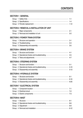
  • 1. CONTENTS SECTION 1 GENERAL Group 1 Safety hints ---------------------------------------------------------------------------------------------------- 1-1 Group 2 Specifications ------------------------------------------------------------------------------------------------ 1-4 Group 3 Periodic replacement ------------------------------------------------------------------------------------- 1-12 SECTION 2 REMOVAL & INSTALLATION OF UNIT Group 1 Major components ---------------------------------------------------------------------------------------- 2-1 Group 2 Removal and installation of unit ------------------------------------------------------------------- 2-2 SECTION 3 POWER TRAIN SYSTEM Group 1 Structure and operation --------------------------------------------------------------------------------- 3-1 Group 2 Troubleshooting --------------------------------------------------------------------------------------------- 3-4 Group 3 Disassembly and assembly -------------------------------------------------------------------------- 3-5 SECTION 4 BRAKE SYSTEM Group 1 Structure and function ----------------------------------------------------------------------------------- 4-1 Group 2 Operational checks and troubleshooting ------------------------------------------------------ 4-5 Group 3 Tests and adjustments ---------------------------------------------------------------------------------- 4-7 SECTION 5 STEERING SYSTEM Group 1 Structure and function ----------------------------------------------------------------------------------- 5-1 Group 2 Operational checks and troubleshooting ------------------------------------------------------- 5-10 Group 3 Disassembly and assembly -------------------------------------------------------------------------- 5-13 SECTION 6 HYDRAULIC SYSTEM Group 1 Structure and function ----------------------------------------------------------------------------------- 6-1 Group 2 Operational checks and troubleshooting ------------------------------------------------------- 6-16 Group 3 Disassembly and assembly --------------------------------------------------------------------------- 6-20 SECTION 7 ELECTRICAL SYSTEM Group 1 Component location -------------------------------------------------------------------------------------- 7-1 Group 2 Electrical circuit ---------------------------------------------------------------------------------------------- 7-2 Group 3 Electric components -------------------------------------------------------------------------------------- 7-3 SECTION 8 MAST Group 1 Structure -------------------------------------------------------------------------------------------------------- 8-1 Group 2 Operational checks and troubleshooting ------------------------------------------------------- 8-6 Group 3 Adjustment ----------------------------------------------------------------------------------------------------- 8-9 Group 4 Removal and installation -------------------------------------------------------------------------------- 8-12
  • 2. 0-1 FOREWORD 1. STRUCTURE This service manual has been prepared as an aid to improve the quality of repairs by giving the serviceman an accurate understanding of the product and by showing him the correct way to perform repairs and make judgements. Make sure you understand the contents of this manual and use it to full effect at every opportunity. This service manual mainly contains the necessary technical information for operations performed in a service workshop. For ease of understanding, the manual is divided into the following sections. SECTION 1 GENERAL This section gives the general information of the machine and explains the safety hints for maintenance. SECTION 2 REMOVAL & INSTALLATION OF UNIT This section explains the procedures and techniques of removal and installation of each component. SECTION 3 POWER TRAIN SYSTEM This section explains the structure of the transmission as well as control valve and drive axle. SECTION 4 BRAKE SYSTEM This section explains the brake piping, each component and operation. SECTION 5 STEERING SYSTEM This section explains the structure of the steering unit, priority valve, trail axle as well as steering circuit and operation. SECTION 6 HYDRAULIC SYSTEM This section explains the structure of the gear pump, main control valve as well as work equipment circuit, each component and operation. SECTION 7 ELECTRICAL SYSTEM This section explains the electrical circuit and each component. It serves not only to give an understanding electrical system, but also serves as reference material for troubleshooting. SECTION 8 MAST This section explains the structure of mast, carriage, backrest and forks. The specifications contained in this service manual are subject to change at any time and without any advance notice. Contact your HYUNDAI distributor for the latest information.
  • 3. 0-2 Revised edition mark( ) When a manual is revised, an edition mark is recorded on the bottom outside corner of the pages. RRevisions Revised pages are shown at the list of revised pages on the between the contents page and section 1 page. Symbols So that the shop manual can be of ample practical use, important places for safety and quality are marked with the following symbols. 2. HOW TO READ THE SERVICE MANUAL Distribution and updating Any additions, amendments or other changes will be sent to HYUNDAI distributors. Get the most up-to-date information before you start any work. Filing method See the page number on the bottom of the page. File the pages in correct order. Following examples shows how to read the page number. Example 1 2 - 3 Item number(2. Structure and Function) Consecutive page number for each item. Additional pages : Additional pages are indicated by a hyphen(-) and number after the page number. File as in the example. 1. 2. 3. Symbol Item Remarks Special safety precautions are necessary when performing the work. Extra special safety precautions are necessary when performing the work because it is under internal pressure. Special technical precautions or other precautions for preserving standards are necessary when performing the work. Safety Caution 10 - 4 10 - 4 - 1 10 - 4 - 2 10 - 5 Added pages
  • 4. 0-3 3. CONVERSION TABLE Method of using the Conversion Table The Conversion Table in this section is provided to enable simple conversion of figures. For details of the method of using the Conversion Table, see the example given below. Example Method of using the Conversion Table to convert from millimeters to inches Convert 55mm into inches. Locate the number 50in the vertical column at the left side, take this as , then draw a horizontal line from . Locate the number 5in the row across the top, take this as , then draw a perpendicular line down from . Take the point where the two lines cross as . This point gives the value when converting from millimeters to inches. Therefore, 55mm = 2.165 inches. Convert 550mm into inches. The number 550 does not appear in the table, so divide by 10(Move the decimal point one place to the left) to convert it to 55mm. Carry out the same procedure as above to convert 55mm to 2.165 inches. The original value(550mm) was divided by 10, so multiply 2.165 inches by 10(Move the decimal point one place to the right) to return to the original value. This gives 550mm = 21.65 inches. 1. 2. (1) (2) (3) (1) (2) (3) Millimeters to inches 1mm = 0.03937 in 0 1 2 3 4 5 6 7 8 9 0 0.039 0.079 0.118 0.157 0.197 0.236 0.276 0.315 0.354 10 0.394 0.433 0.472 0.512 0.551 0.591 0.630 0.669 0.709 0.748 20 0.787 0.827 0.866 0.906 0.945 0.984 1.024 1.063 1.102 1.142 30 1.181 1.220 1.260 1.299 1.339 1.378 1.417 1.457 1.496 1.536 40 1.575 1.614 1.654 1.693 1.732 1.772 1.811 1.850 1.890 1.929 50 1.969 2.008 2.047 2.087 2.126 2.165 2.205 2.244 2.283 2.323 60 2.362 2.402 2.441 2.480 2.520 2.559 2.598 2.638 2.677 2.717 70 2.756 2.795 2.835 2.874 2.913 2.953 2.992 3.032 3.071 3.110 80 3.150 3.189 3.228 3.268 3.307 3.346 3.386 3.425 3.465 3.504 90 3.543 3.583 3.622 3.661 3.701 3.740 3.780 3.819 3.858 3.898
  • 5. 0-4 Millimeters to inches 1mm = 0.03937in 0 1 2 3 4 5 6 7 8 9 0 0.039 0.079 0.118 0.157 0.197 0.236 0.276 0.315 0.354 10 0.394 0.433 0.472 0.512 0.551 0.591 0.630 0.669 0.709 0.748 20 0.787 0.827 0.866 0.906 0.945 0.984 1.024 1.063 1.102 1.142 30 1.181 1.220 1.260 1.299 1.339 1.378 1.417 1.457 1.496 1.536 40 1.575 1.614 1.654 1.693 1.732 1.772 1.811 1.850 1.890 1.929 50 1.969 2.008 2.047 2.087 2.126 2.165 2.205 2.244 2.283 2.323 60 2.362 2.402 2.441 2.480 2.520 2.559 2.598 2.638 2.677 2.717 70 2.756 2.795 2.835 2.874 2.913 2.953 2.992 3.032 3.071 3.110 80 3.150 3.189 3.228 3.268 3.307 3.346 3.386 3.425 3.465 3.504 90 3.543 3.583 3.622 3.661 3.701 3.740 3.780 3.819 3.858 3.898 Kilogram to Pound 1kg = 2.2046lb 0 1 2 3 4 5 6 7 8 9 0 2.20 4.41 6.61 8.82 11.02 13.23 15.43 17.64 19.84 10 22.05 24.25 26.46 28.66 30.86 33.07 35.27 37.48 39.68 41.89 20 44.09 46.30 48.50 50.71 51.91 55.12 57.32 59.5. 61.73 63.93 30 66.14 68.34 70.55 72.75 74.96 77.16 79.37 81.57 83.78 85.98 40 88.18 90.39 92.59 94.80 97.00 99.21 101.41 103.62 105.82 108.03 50 110.23 112.44 114.64 116.85 119.05 121.25 123.46 125.66 127.87 130.07 60 132.28 134.48 136.69 138.89 141.10 143.30 145.51 147.71 149.91 152.12 70 154.32 156.53 158.73 160.94 163.14 165.35 167.55 169.76 171.96 174.17 80 176.37 178.57 180.78 182.98 185.19 187.39 189.60 191.80 194.01 196.21 90 198.42 200.62 202.83 205.03 207.24 209.44 211.64 213.85 216.05 218.26
  • 6. 0-5 Liter to U.S. Gallon 1 = 0.2642 U.S.Gal 0 1 2 3 4 5 6 7 8 9 0 0.264 0.528 0.793 1.057 1.321 1.585 1.849 2.113 2.378 10 2.642 2.906 3.170 3.434 3.698 3.963 4.227 4.491 4.755 5.019 20 5.283 5.548 5.812 6.6076 6.340 6.604 6.869 7.133 7.397 7.661 30 7.925 8.189 8.454 8.718 8.982 9.246 9.510 9.774 10.039 10.303 40 10.567 10.831 11.095 11.359 11.624 11.888 12.152 12.416 12.680 12.944 50 13.209 13.473 13.737 14.001 14.265 14.529 14.795 15.058 15.322 15.586 60 15.850 16.115 16.379 16.643 16.907 17.171 17.435 17.700 17.964 18.228 70 18.492 18.756 19.020 19.285 19.549 19.813 20.077 20.341 20.605 20.870 80 21.134 21.398 21.662 21.926 22.190 22.455 22.719 22.983 23.247 23.511 90 23.775 24.040 24.304 24.568 24.832 25.096 25.631 25.625 25.889 26.153 Liter to U.K. Gallon 1 = 0.21997 U.K.Gal 0 1 2 3 4 5 6 7 8 9 0 0.220 0.440 0.660 0.880 1.100 1.320 1.540 1.760 1.980 10 2.200 2.420 2.640 2.860 3.080 3.300 3.520 3.740 3.950 4.179 20 4.399 4.619 4.839 5.059 5.279 5.499 5.719 5.939 6.159 6.379 30 6.599 6.819 7.039 7.259 7.479 7.969 7.919 8.139 8.359 8.579 40 8.799 9.019 9.239 9.459 9.679 9.899 10.119 10.339 10.559 10.778 50 10.998 11.281 11.438 11.658 11.878 12.098 12.318 12.528 12.758 12.978 60 13.198 13.418 13.638 13.858 14.078 14.298 14.518 14.738 14.958 15.178 70 15.398 15.618 15.838 16.058 16.278 16.498 16.718 16.938 17.158 17.378 80 17.598 17.818 18.037 18.257 18.477 18.697 18.917 19.137 19.357 19.577 90 19.797 20.017 20.237 20.457 20.677 20.897 21.117 21.337 21.557 21.777
  • 7. 0-6 kgf m to lbf ft 1kgf m = 7.233lbf ft 0 1 2 3 4 5 6 7 8 9 7.2 14.5 21.7 28.9 36.2 43.4 50.6 57.9 65.1 10 72.3 79.6 86.8 94.0 101.3 108.5 115.7 123.0 130.2 137.4 20 144.7 151.9 159.1 166.4 173.6 180.8 188.1 195.3 202.5 209.8 30 217.0 224.2 231.5 238.7 245.9 253.2 260.4 267.6 274.9 282.1 40 289.3 396.6 303.8 311.0 318.3 325.5 332.7 340.0 347.2 354.4 50 361.7 368.9 376.1 383.4 390.6 397.8 405.1 412.3 419.5 426.8 60 434.0 441.2 448.5 455.7 462.9 470.2 477.4 484.6 491.8 499.1 70 506.3 513.5 520.8 528.0 535.2 542.5 549.7 556.9 564.2 571.4 80 578.6 585.9 593.1 600.3 607.6 614.8 622.0 629.3 636.5 643.7 90 651.0 658.2 665.4 672.7 679.9 687.1 694.4 701.6 708.8 716.1 100 723.3 730.5 737.8 745.0 752.2 759.5 766.7 773.9 781.2 788.4 110 795.6 802.9 810.1 817.3 824.6 831.8 839.0 846.3 853.5 860.7 120 868.0 875.2 882.4 889.7 896.9 904.1 911.4 918.6 925.8 933.1 130 940.3 947.5 954.8 962.0 969.2 976.5 983.7 990.9 998.2 10005.4 140 1012.6 1019.9 1027.1 1034.3 1041.5 1048.8 1056.0 1063.2 1070.5 1077.7 150 1084.9 1092.2 1099.4 1106.6 1113.9 1121.1 1128.3 1135.6 1142.8 1150.0 160 1157.3 1164.5 1171.7 1179.0 1186.2 1193.4 1200.7 1207.9 1215.1 1222.4 170 1129.6 1236.8 1244.1 1251.3 1258.5 1265.8 1273.0 1280.1 1287.5 1294.7 180 1301.9 1309.2 1316.4 1323.6 1330.9 1338.1 1345.3 1352.6 1359.8 1367.0 190 1374.3 1381.5 1388.7 1396.0 1403.2 1410.4 1417.7 1424.9 1432.1 1439.4
  • 8. 0-7 kgf/cm2 to lbf/in2 1kgf / cm2 = 14.2233lbf / in2 0 1 2 3 4 5 6 7 8 9 14.2 28.4 42.7 56.9 71.1 85.3 99.6 113.8 128.0 10 142.2 156.5 170.7 184.9 199.1 213.4 227.6 241.8 256.0 270.2 20 284.5 298.7 312.9 327.1 341.4 355.6 369.8 384.0 398.3 412.5 30 426.7 440.9 455.1 469.4 483.6 497.8 512.0 526.3 540.5 554.7 40 568.9 583.2 597.4 611.6 625.8 640.1 654.3 668.5 682.7 696.9 50 711.2 725.4 739.6 753.8 768.1 782.3 796.5 810.7 825.0 839.2 60 853.4 867.6 881.8 896.1 910.3 924.5 938.7 953.0 967.2 981.4 70 995.6 1010 1024 1038 1053 1067 1081 1095 1109 1124 80 1138 1152 1166 1181 1195 1209 1223 1237 1252 1266 90 1280 1294 1309 1323 1337 1351 1365 1380 1394 1408 100 1422 1437 1451 1465 1479 1493 1508 1522 1536 1550 110 1565 1579 1593 1607 1621 1636 1650 1664 1678 1693 120 1707 1721 1735 1749 1764 1778 1792 1806 1821 1835 130 1849 2863 1877 1892 1906 1920 1934 1949 1963 1977 140 1991 2005 2020 2034 2048 2062 2077 2091 2105 2119 150 2134 2148 2162 2176 2190 2205 2219 2233 2247 2262 160 2276 2290 2304 2318 2333 2347 2361 2375 2389 2404 170 2418 2432 2446 2460 2475 2489 2503 2518 2532 2546 180 2560 2574 2589 5603 2617 2631 2646 2660 2674 2688 200 2845 2859 2873 2887 2901 2916 2930 2944 2958 2973 210 2987 3001 3015 3030 3044 3058 3072 3086 3101 3115 220 3129 3143 3158 3172 3186 3200 3214 3229 3243 3257 230 3271 3286 3300 3314 3328 3343 3357 3371 3385 3399 240 3414 3428 3442 3456 3470 3485 3499 3513 3527 3542
  • 9. TEMPERATURE Fahrenheit-Centigrade Conversion. A simple way to convert a fahrenheit temperature reading into a centigrade temperature reading or vice verse is to enter the accompanying table in the center or boldface column of figures. These figures refer to the temperature in either Fahrenheit or Centigrade degrees. If it is desired to convert from Fahrenheit to Centigrade degrees, consider the center column as a table of Fahrenheit temperatures and read the corresponding Centigrade temperature in the column at the left. If it is desired to convert from Centigrade to Fahrenheit degrees, consider the center column as a table of Centigrade values, and read the corresponding Fahrenheit temperature on the right. 0-8 C F C F C F C F -40.4 -40 -40.0 -11.7 11 51.8 7.8 46 114.8 27.2 81 117.8 -37.2 -35 -31.0 -11.1 12 53.6 8.3 47 116.6 27.8 82 179.6 -34.4 -30 -22.0 -10.6 13 55.4 8.9 48 118.4 28.3 83 181.4 -31.7 -25 -13.0 -10.0 14 57.2 9.4 49 120.2 28.9 84 183.2 -28.9 -20 -4.0 -9.4 15 59.0 10.0 50 122.0 29.4 85 185.0 -28.3 -19 -2.2 -8.9 16 60.8 10.6 51 123.8 30.0 86 186.8 -27.8 -18 -0.4 -8.3 17 62.6 11.1 52 125.6 30.6 87 188.6 -27.2 -17 1.4 -7.8 18 64.4 11.7 53 127.4 31.1 88 190.4 -26.7 -16 3.2 -6.7 20 68.0 12.8 55 131.0 32.2 90 194.0 -26.1 -15 5.0 -6.7 20 68.0 12.8 55 131.0 32.2 90 194.0 -25.6 -14 6.8 -6.1 21 69.8 13.3 56 132.8 32.8 91 195.8 -25.0 -13 8.6 -5.6 22 71.6 13.9 57 134.6 33.3 92 197.6 -24.4 -12 10.4 -5.0 23 73.4 14.4 58 136.4 33.9 93 199.4 -23.9 -11 12.2 -4.4 24 75.2 15.0 59 138.2 34.4 94 201.2 -23.3 -10 14.0 -3.9 25 77.0 15.6 60 140.0 35.0 95 203.0 -22.8 -9 15.8 -3.3 26 78.8 16.1 61 141.8 35.6 96 204.8 -22.2 -8 17.6 -2.8 27 80.6 16.7 62 143.6 36.1 97 206.6 -21.7 -7 19.4 -2.2 28 82.4 17.2 63 145.4 36.7 98 208.4 -21.1 -6 21.2 -1.7 29 84.2 17.8 64 147.2 37.2 99 210.2 -20.6 -5 23.0 -1.1 35 95.0 21.1 70 158.0 51.7 125 257.0 -20.0 -4 24.8 -0.6 31 87.8 18.9 66 150.8 40.6 105 221.0 -19.4 -3 26.6 0 32 89.6 19.4 67 152.6 43.3 110 230.0 -18.9 -2 28.4 0.6 33 91.4 20.0 68 154.4 46.1 115 239.0 -18.3 -1 30.2 1.1 34 93.2 20.6 69 156.2 48.9 120 248.0 -17.8 0 32.0 1.7 35 95.0 21.1 70 158.0 51.7 125 257.0 -17.2 1 33.8 2.2 36 96.8 21.7 71 159.8 54.4 130 266.0 -16.7 2 35.6 2.8 37 98.6 22.2 72 161.6 57.2 135 275.0 -16.1 3 37.4 3.3 38 100.4 22.8 73 163.4 60.0 140 284.0 -15.6 4 39.2 3.9 39 102.2 23.3 74 165.2 62.7 145 293.0 -15.0 5 41.0 4.4 40 104.0 23.9 75 167.0 65.6 150 302.0 -14.4 6 42.8 5.0 41 105.8 24.4 76 168.8 68.3 155 311.0 -13.9 7 44.6 5.6 42 107.6 25.0 77 170.6 71.1 160 320.0 -13.3 8 46.4 6.1 43 109.4 25.6 78 172.4 73.9 165 329.0 -12.8 9 48.2 6.7 44 111.2 26.1 79 174.2 76.7 170 338.0 -12.2 10 50.0 7.2 45 113.0 26.7 80 176.0 79.4 172 347.0
  • 10. 5-13 GROUP 3 DISASSEMBLY AND ASSEMBLY 1. STEERING UNIT STRUCTURE1) 1 27-2 5 15 6 8 2 18 11 3 22 21 23 27-4 27-3 27-1 4 13 14 24 24 29-5 29-6 29-4 29-3 29-1 29-2 20 17 9 12 7 10 19 16 13 10 10 22B7SS08 1 Dust seal 2 Retaining seal 3 Cap seal 4 Thrust bearing 5 Ball 6 Pin 7 Spacer 8 Centering spring 9 Washer 10 O-ring 11 O-ring 12 Rolled screw 13 Gerotor set 14 Bearing race 15 Bore screw 16 Drive 17 End cap 18 Gland bushing 19 Plate 20 Cap screw 21 Housing 22 Spool 23 Sleeve 24 Plate spring 27 P-port check valve 27-1 Plug 27-2 Poppet 27-3 Spring seat 27-4 Spring 29 Relief valve 29-1 Spool 29-2 Bushing 29-3 Spring 29-4 Spring seat 29-5 Plug 29-6 O-ring
  • 11. 5-14 TOOLS Holding tool. 2) (1) Assembly tool for O-ring and kin-ring.(2) Assembly tool for lip seal.(3) Assembly tool for cardan shaft.(4) 5-69(1) 5-69(2) 5-69(3) 5-69(4)
  • 12. 5-15 Assembly tool for dust seal.(5) Torque wrench 0~7.1kgf m (0~54.4lbf ft) 13mm socket spanner 6, 8mm and 12mm hexagon sockets 12mm screwdriver 2mm screwdriver 13mm ring spanner 6, 8 and 12mm hexagon socket spanners Plastic hammer Tweezers (6) 5-70(1) 5-70(2) D353SE23 TIGHTENING TORQUE L : Left port R : Right port T : Tank P : Pump 3) Port L R T P Mounting bolt Size 3/4 UNF - 16 3/4 UNF - 16 3/4 UNF - 16 3/4 UNF - 16 M10 1.5 Torque [kgf m(lbf ft)] 6.1 0.6 (44.1 4.3) 6.1 0.6 (44.1 4.3) 6.1 0.6 (44.1 4.3) 6.1 0.6 (44.1 4.3) 4.0 0.5 (29 3.6)
  • 13. 5-16 DISASSEMBLY Disassemble steering column from steering unit and place the steering unit in the holding tool. Screw out the screws in the end cover(6- off plus one special screw). 4) (1) Remove the end cover, sideways.(2) Lift the gearwheel set(With spacer if fitted) off the unit. Take out the two O-rings. (3) Remove cardan shaft.(4) 5-72(1) 5-72(2) 5-72(3) 5-72(4)
  • 14. 5-17 Remove distributor plate.(5) Screw out the threaded bush over the check valve. (6) Remove O-ring.(7) Shake out the check valve ball.(8) 5-73(1) 5-73(2) 5-73(3) B20H7SS09
  • 15. 5-18 Take ring, bearing races and thrust bearing from sleeve and spool. The outer (Thin) bearing race can sometimes "stick" in the housing, therefore check that it has come out. (10) Press out the cross pin. Use the special screw from the end cover. (11) A small mark has been made with a pumice stone on both spool and sleeve close to one of the slots for the neutral position springs(See drawing). If the mark is not visible, remember to leave a mark of your own on sleeve and spool before the neutral position springs are disassembled. Take care to keep the cross pin in the sleeve and spool horizontal. The pin can be seen through the open end of the spool. Press the spool inwards and the sleeve, ring, bearing races and thrust bearing will be pushed out of the housing together. (9) 5-73(4) 5-74(1) 5-74(2) 5-74(3)
  • 16. 5-19 Press the neutral position springs out of their slots in the spool. (13) Remove dust seal and O-ring.(14) Disassembling the pressure relief valve Screw out the plug using an 8mm hexagon socket spanner. Remove seal washers. (15) Carefully press the spool out of the sleeve.(12) 5-74(4) 5-75(1) 5-75(2) D353SE10
  • 17. 5-20 Unscrew the setting screw using an 8mm hexagon socket spanner. (16) Shake out spring and piston. The valve seat is bonded into the housing and cannot be removed. (17) The pressure relief valve is now disassem- bled. (18) D353SE11 D353SE12 D353SE13
  • 18. Thank you very much for your reading. Please Click Here. Then Get COMPLETE MANUAL. NO WAITING NOTE: If there is no response to click on the link above, please download the PDF document first and then click on it.
  • 19. 5-21 ASSEMBLY Assemble spool and sleeve. When assembling spool and sleeve only one of two possible ways of positioning the spring slots is correct. There are three slots in the spool and three holes in the sleeve in the end of the spool / sleeve opposite to the end with spring slots. Place the slots and holes opposite each other so that parts of the holes in the sleeve are visible through the slots in the spool. 5) (1) Place the two flat neutral position springs in the slot. Place the curved springs between the flat ones and press them into place (see assembly pattern). (2) Line up the spring set.(3) 5-76(1) 5-76(2) 5-76(4) Guide the spool into the sleeve. Make sure that spool and sleeve are placed correctly in relation to each other. (4) 5-77(1)
  • 20. 5-22 Press the springs together and push the neutral position springs into place in the sleeve. (5) Line up the springs and center them.(6) Guide the ring down over the sleeve. The ring should be able to rotate free of the springs. (7) 5-77(2) 5-77(3) 5-77(4) Fit the cross pin into the spool / sleeve.(8) 5-78(1)