
Recommended
Recommended
More Related Content
What's hot
What's hot (20)
Similar to Suzuki outboard dt8 c, dt8c sail, dt9.9c, dt9.9c sail, dt9.9, dt16, dt20, dt25, dt25c service repair manual
Similar to Suzuki outboard dt8 c, dt8c sail, dt9.9c, dt9.9c sail, dt9.9, dt16, dt20, dt25, dt25c service repair manual (20)
More from fjjsekkfksmem
More from fjjsekkfksmem (20)
Recently uploaded
Recently uploaded (20)
Suzuki outboard dt8 c, dt8c sail, dt9.9c, dt9.9c sail, dt9.9, dt16, dt20, dt25, dt25c service repair manual
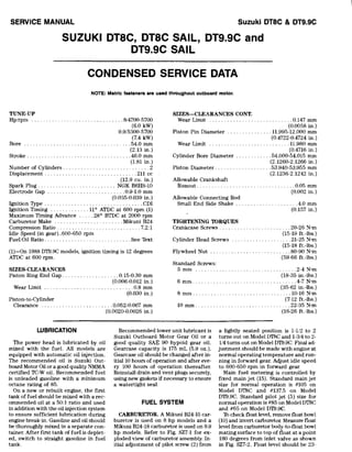
- 1. SERVICE MANUAL Suzuki DT8C & DT9.9C SUZUKI DT8C, DT8C SAIL, DT9.9C and DT9.9C SAIL CONDENSED SERVICE DATA NOTE: Metric faateners ara uaad throughout outboard motor_ TUNE-UP Hplrpm ... . .................... .8/4700-5700 (6.0 kW) 9.9/5300-5700 (7.4 kW) Bore. . . . ............................. 54.0 mm (2.13 in.) Stroke. . . . . . . . . . ................. .46.0 mm (1.81 in.) Number of Cylinders ............................. 2 Displacement ............................... 211 cc (12.9 cu. in.) Spark Plug .......................... NGK B6HS-1O Electrode Gap .......................... 0.9-1.0 mm (0.035-0.039 in.) Ignition Type ................................. CDI Ignition Timing ............. 110 ATDC at 600 rpm (1) Maximum Timing Advance ..... 280 BTDC at 2000 rpm Carburetor Make ....................... Mikuni B24 Compression Ratio. . . . . . . . . . . . . . . . . . . . .. . .... 7.2:1 Idle Speed (in gear)..600-650 rpm Fuel:Oil Ratio ............................. See '!ext (I)-On 1988 DT9.9C models, ignition timing is 12 degrees ATDC at 600 rpm. SIZES-CLEARANCES Piston Ring End Gap ................... 0.15-0.30 mm (0.006-0.012 in.) Wear Limit . . . . . . . . . . . . . . . . . . . . . . . .. . ... 0.8 mm (0.030 in.) Piston-to-Cylinder Clearance .................. . .0.052-0.067 mm (0.0020-0.0026 in.) SIZES-CLEARANCES CONT_ Wear Limit ...................... " .... 0.147 mm (0.0058 in.) Piston Pin Diameter ............... 11.995-12.000 mm (0.4722-0.4724 in.) Wear Limit ........................... 11.980 mm (0.4716 in.) Cylinder Bore Diameter .. . . . . . . .54.000-54.015 mm (2.1260-2.1266 in.) Piston Diameter ................... 53.940-53.955 mm (2.1236-2.1242 in.) Allowable Crankshaft Runout ....... . Allowable Connecting Rod Small End Side Shake ....... . TIGHTENING TORQUES ........ 0'()5 mm (0.002 in.) . .. 4.0 mm (0.157 in.) Crankcase Screws. . . . . . . . . . . . . . . . .. 20-26 N-m (15-19 ft.-Ibs.) Cylinder Head Screws .................... 21-25 N-m (15-18 ft.-Ibs.) Flywheel Nut ........................... 80-90 N-m (59-66 (tAbs.) Standard Screws: 5 mm ............ 2-4 N-m (18-35 in.-Ibs.) 6 mm. ........................... .4-7 N-m (35-62 in.-Ibs.) 8 mm ........ . ..................... 10-16 N-m (7-12 ft.-lbs.) 10 mm ....... . .................. 22-35 N'm (16-26 ft.-bs.) WBRICATION The power head is lubricated by oil mixed with the fuel. All models are equipped with automatic oil injection. The recommended oil is Suzuki Out- board Motor Oil or a good quality NMMA certified TC-W oil. Recommended fuel is unleaded gasoline with a minimum octane rating of 85. Recommended lower unit lubricant is Suzuki Outboard Motor Gear Oil or a good quality SAE 90 hypoid gear oil. Gearcase capacity is 175 mL (5.9 oz.). Gearcase oil should be changed after in- itial 10 hours of operation and after eve- ry 100 hours of operation thereafter. Reinstall drain and vent plugs securely, using new gaskets if necessary to ensure a watertight seal. a lightly seated position is 1-1/2 to 2 turns out on Model DTl3C and 1-3/4 to 2- 114 turns out on Model DT9.9C. Final ad- justment should be made with engine at normal operating temperature and run- ning in forward gear. Adjust idle speed to 600-650 rpm in forward gear. Main fuel metering is controlled by fixed main jet (15). Standard main jet size for normal operation is #105 on Model DTl3C and #137.5 on Model DT9.9C. Standard pilot jet (5) size for normal operation is #85 on Model DTl3C and #65 on Model DT9.9C, On a new or rebuilt engine, the first tank of fuel should be mixed with a rec- ommended oil at a 50:1 ratio and used in addition with the oil injection system to ensure sufficient lubrication during engine break-in. Gasoline and oil should be thoroughly mixed in a separate con- tainer. After first tank of fuel is deplet- ed, switch to straight gasoline in fuel tank. FUEL SYSTEM CARBURETOR. A Mikuni B24-15 car- buretor is used on 8 hp models and a Mikuni B24-18 carburetor is used on 9.9 hp models. Refer to Fig. SZ7-1 for ex- ploded view of carburetor assembly. In- itial adjustment of pilot screw (2) from 1b check float level, remove float bowl (10) and invert carburetor. Measure float level from carburetor body-to-float bowl mating surface to top of float at a point 180 degrees from inlet valve as shown in Fig. SZ7-2. Fioat level should be 23-
- 2. Suzuki DT9.9 & DT16 (Prior To 1983) OUTBOARD MOTOR SUZUKI DT9.9 AN0 DT16 (PRIOR TO 1983) CONDENSED SERVICE DATA NOTE: Metric fasteners are used throughout outboard motor. TUNE·UP DT9.9 Horsepower ....................... . 9.9 Bore.............................. . 56mm Stroke ............................ . 52mm Displacement ...................... . 256 cc Spark Plug: NGK ............................ . B6HS Electrode gap .................... . 0.6·0.7 mm Magneto: Breaker point gap ................. . Breakerless Carburetor: Make ........................... . Mikuni Model ........................... . BV24·16 Fuel:OiI Ratio ...................... . 5.0:1 SIZES-CLEARANCES Piston Ring End Gap ................ . 0.15-0.35 mm Piston Pin Diameter ................. . 13.995-14.000 mm Piston to Cylinder Wall Clearance ........................ . 0.042-0.058 mm Max. Crankshaft Runout at Main Bearing Journal. ............. . 0.05 mm Max. Connecting Rod Small End Side Shake ....................... . 4.0mm TIGHTENING TORQUES Cylinder Head ...................... . 18-28 N'm Crankcase: 6mm .......................... .. 8-12 N'm 8mm .......................... .. 18-28 N'm Flywheel Nut ...................... . 8()..90 N'm Standard Screws: 5mm .......................... . 2-4 N'm 6mm .......................... . 4·7 N'm 8mm ........................... . 10-16 N'm 10mm .......................... . 22·35 N'm LUBRICATION The power head is lubricated by oil mixed with the fuel. Fuel:oil ratios should be 30:1 during break-in of a new or rebuilt engine and 50:1 for normal service when using a NMMA certified two-stroke engine oil or Suzuki "eCI" oil. When using any other type of two- stroke engine oil, fuel:oil ratios should be 20:1 during break-in and 30:1 for normal service. Manufacturer recom· mends regular or no-lead automotive gasoline having an 85-95 octane rating. Gasoline and oil should be thoroughly mixed. The lower unit gears and bearings are lubricated by oil contained in the gear- DT16 16 59mm 52mm 284 cc B7HS 0.6-0.7 mm Breakerless Mikuni BV24·19 50:1 0.15-0.35 mm 13.995-14.000 mm 0.042-0.058 mm 0.05 mm 4.0mm 18-28 N'm 8·12 N'm 18·28 N'm 80·90 N'm 2·4 N'm 4-7 N'm 10-16 N'm 22·35 N'm case. SAE 90 hypoid outboard gear oil is recommended. Oil capacity of gear- case with integral exhaust outlet in the lower housing is approximately 220 mL. Oil capacity of gearcase with through· the-propeller exhaust is approximately 200 mL. Reinstall vent and fill plugs se· curely using a new gasket, if necessary, to ensure a water tight seal.
- 3. SERVICE MANUAL Suzuki DT20 & DT25 (Prior To 1983) SUZUKI DT20 and DT25 (PRIOR TO 1983) CONDENSED SERVICE DATA NOTE: Metric fasteners are used throughout outboard motor_ TUNE-UP DT20 Hp ............................... . 19.8 Bore.............................. . 64mm Stroke ............................ . 61.5 mm Displacement ...................... . 396 cc Spark Plug: NGK ............................ . B7HS Electrode Gap .................... . 0.6·0.7 mm Magneto: Breaker Point Gap ................ . Breakerless Carburetor: Make ........................... . Mikuni Model ........................... . BV28-22 Fuel:Oil Ratio ...................... . 50:1 SIZES-CLEARANCES Piston Ring End Gap ................ . Piston Pin Diameter ................. . 0.15-0.35 mm 15.995·i6.000 mm Piston to Cylinder Wall Clearance ..... . 0.060·0.090 mm Max. Crankshaft Runout at Main Bearing Joumal .................. . 0.05 mm Max. Con. Rod Small End Side Shake ........................... . 5.0mm TIGHTENING TORQUES Cylinder Head...................... . 18·28 N-m Crankcase ......................... . 18·28 N'm Exhaust Cover ..................... . 8·12 N'm Flywheel Nut ...................... . 1()()"110 N-m Standard Screws: 5mm .......................... . 2·4 N-m 6mm .......................... . 4·7 N-m 8mm .......................... . 10·16 N-m 10mm .......................... . 22·35 N-m LUBRICATION regular or no·lead automotive gasoline having an 85·95 octane rating. Gasoline and oil should be thoroughly mixed. The power head is lubricated by oil mixed with the fuel. Fuel:oil ratios should be 30:1 during break·in of a new or rebuilt engine and 50:1 for normal service when using a BIA certified two· stroke engine oil or Suzuki ·CCI" oiL When using any other type of two- stroke engine oil, fuel:oil ratios should be 20:1 during break-in and 30:1 for nor· mal service. Manufacturer recommends The lower unit gears and bearings are lubricated by oil contained in the gear· case. SAE 90 hypoid outboard gear oil should be used. Gearcases with exhaust outlet in gearcase require 380 mL of gear oil while through·the·propeller ex· haust models reqlire 300 mL of gear oil. Reinstall vent and fill plugs securely us- ing a new gasket, if necessary, to ensure a water tight seal. DT25 25 68mm 61.5 mm 447 cc B7HS 0.6·0.7 mm Breakerless Mikuni BV32-28 50:1 0.15-0.35 mm 15.995·16.000 mm 0.060-0.090 mm 0.05 mm 5.0mm 18·28 N'm 18·28 N-m 8·12 N'm 100·110 N'm 2·4 N-m 4-7 N-m 10-16 N-m 22·35 N-m FUEL SYSTEM CARBURETOR. A Mikuni car- buretor is used on all models. Refer to Fig. SZ8·1 for exploded view. Initial set- ting of pilot air screw (5) from a lightly seated position should be 11 12.2 turns on DT20 models and 11/••13/. turns on DT25 models. Final carburetor adjustment should be made with engine at normal operating temperature and running in forward gear. Adjust throttle stop -
- 4. SERVICE MANUAL Suzuki DT20 (1986-1988) & DT25 (1985-1988) SUZUKI DT20 (1986-1988) AND DT25 (1985-1988) CONDENSED SERVICE DATA NOTE: Metric fasteners are used throughout outboard motor. TUNE·UP Hp/rpm .........................'.......20/4800-5500 25/4800·5500 Bore: DT20 ......................................67mm (2.64 in.) DT25 ..................................... 71mm (2.80 in.) Stroke ...................................... 63 mm (2.48 in.) Number of Cylinders ............................... 2 Displacement: DT20 ..................................... .444cc (27.10 cu. in.) DT25 ...................................... 499cc (30.45 cu. in.) Spark Plug: NGK ..................................... BR7HS Electrode Gap .......................... 0.8-0.9 mm (0.031-0.035 in.) Ignition Type .................................CD! Carburetor Make ........................... Mikuni Idle Speed (in gear) .................... 650·700 rpm Fuel:Oil Ratio ........................... , .See Text SIZES-CLEARANCES Piston Ring End Gap ..... . Piston-to-Cylinder Clearance: ............ 0.2·0.4 mm (0.008-0.016 in.) Prior to 1987 ...................... 0.067-0.082 mm (0.0026-0.0032 in.) After 1986 ........................ 0.087-0.102 mm (0.0034-0.0040 in.) Piston Pin Diameter ................. 17.995-18.000 mm (0.7085·0.7087 in.) Max. Crankshaft Runout at Main Bearing Journal ................... , ... ".,0.05 mm (0.002 in.) Max. Connecting Rod Small End Side Shake ................................. 5.0 mm (0.20 in.) TIGHTENING TORQUES Power Head Mounting Screws ............... 15-20 N' m (11-14 ft.-lbs.1 TIGHTENING TORQUES CONT. Crankcase: 6mm ................................... 8-12N·m (6-8 ft.·lbs.) 8mm .................................. 20-26 N'm (14-19 ft.-Ibs.) FlywheelNut ......... """, ........... 130-150N·m (94-108 ftAbs.) Cylinder Head Screws: 6mm ...................................8·12N·m (6-8 ft.-lbs.) 8mm .................................. 20·26N·m (14-19 ft.-Ibs.) Gearcase Pinion Nut ....................... 18-22 N· m (13-16 ft.-lbs.) Propeller Shaft Nut ........................ 27-30 N· m (19-21 ft.-Ibs.) Standard Screws: Unm.arked or Marked "4" 5mm ................................... 2-4N·m (2-3 ft.-lbs.) 6mm ................................... 4-7N·m (3·5 ft.-lbs.) 8mm ................................. 10-16N·m (7·12 ft.-Ibs.) 10mm ................................ 22-35 N'm (16·26 fUbs.) Stainless Steel 5mm ................................... 2-4 N'm (2-3 fUbs.) 6mm .................................. 6-10 N'm (5-7 ft.-Ibs.) 8 mm ................................. 15-20N'm (11-15 ft.-Ibs.) 10 mm ................................ 34-41 N'm (25-30 ft.-lbs.) Marked "7" or SAE Grade 5 5mm ................. , ................. 3-6N·m (2-5 ftAbs.) 6mm .......... "" ....................8-12N·m (6-9 in.·lbs.) 8mm ................................. 18·28N·m (13·20 fUbs.) 10mm ............................... .40·60 N'm (29-44 ft.-Ibs.) LUBRICATION The power head is lubricated by oil mixed with the fuel. During break-in of a new or rebuilt engine, fuel:oil ratio should be 30:1 on 1985 D'I25 models and 25:1 on 1986 and later D'I25 and all D'I20 models. Fuel:oil ratio for normal service should be 50:1 on 1985 D'I25 models and 100:1 on 1986 and later D'I25 and all D'I20 models. Recom- mended oil is Suzuki Outboard Motor Oil or a good quality NMMA certified Te- W engine oil. Recommended fuel is regular or unleaded gasoline having an 85 minimum octane rating. Manufactur- er does not recommended using gasoline containing alcohol additives. However, unleaded gasoline containing ethanol (grain alcohol) may be used providing ethanol content does not exceed five percent and minimum octane rating is 85. NOTE: Manufacturer recommends NOT using any gllllOline containing methanol (wood alcohol).
- 5. Suzuki DT25C OUTBOARD MOTOR SUZUKI DT25C CONDENSED SERVICE DATA NOTE: Metric fasteners are used throughout outboard motor. TUNE-UP Hp/rpm . .. . ..................... 25/5000-5600 rpm (18.6 kW) Number of Cylinders ............................. 3 Bore ..................................... 62 mm (2.44 in.) Stroke .................................... 60 mm (2.36 in.) Displacement. .............................. 543 cc (33.1 cu. in.) Spark Plug .......................... NGK B7HS-1O Electrode Gap .......................... 0.9-1.0 mm (0.035-0.039 in.) Ignition. . . . . . . . . . . ....................... CD! Carburetor: Make .................................... Mikuni Model ................................... B26-20 Fuel:Oil Ratio ................... Automatic Metering SIZES-CLEARANCES Piston Ring End Gap .................. 0.15-0.35 mm (0.006-0.014 in.) Wear Limit ..............................0.8 mm (0.030 in.) Piston Pin Diameter ............... 15.995-16.000 mm (0.6297-0.6299 in.) Wear Limit ........................... 15.980 mm (0.6291 in.) Piston Pin Bore Diameter .......... 16.002-16.010 mm (0.6300-0.6303 in.) Wear Limit ........................... 16.030 mm (0.6311 in.) Standard Piston Diameter .......... 61.920-61.935 mm (2.4378-2.4384 in.) Standard Cylinder Bore Diameter....................... 62.000-62.015 mm (2.4409-2.4415 in.) Piston-to-Cylinder Clearance ........................ 0.072-0.087 mm (0.0028-0.0034 in.) Wear Limit. . . . . . . ...............0.167 mm Max. Crankshaft Runout at Main Journal ....... . (0.0066 in.) .............0.05 mm (0.002 in.) SIZES-CLEARANCES CONT_ Max. Connecting Rod Small End Side Shake ...................... , ... 5.0 mm TIGHTENING TORQUES Cylinder Head: (0.20 in.) 6 mm ................................. 8-12 N-m (6-9 ftAbs.) 8 mm ................................ 21-25 N'm (15-18 ft.-lbs.) Crankcase: 6 mm ................................. 8-12 N'm (6-9 ft.-Ibs.) 8 mm ................................ 20-26 N-m (15-19 ft.-lbs.) Flywheel Nut. . . . . . . . . . . . . . . . . . .130-150 N-m (96-111 fUbs.) Standard Screws- Unmarked or Marked "4": 5 mm ................................. 2-4 N'm (18-35 in.-lbs.) 6 mm ................................ A-7 N'm (35-62 in.-lbs.) 8 mm ......... , .................... 10-16 N'm (7-12 ft.-lbs.) 10 mm .............................. 22-35 N-m (16-26 fL-lbs.) Stainless Steel: 5 mm ................................. 2-4 N-m (18-35 in.-lbs.) 6 mm ................................ 6-10 N-m (53-88 in.-lbs.) 8 mm ............................... 15-20 N-m (11-15 ft.-lbs.) 10 mm .............................. 34-41 N-m (25-30 ft.-lbs.) Marked "7": 5 mm ................................. 3-6 N-m (27-53 in.-lbs.) 6 mm ................................ 8-12 N-m (6-9 ft..-lbs.) 8 mm ............................... 18-28 N-m (13-21 ft.-lbs.) 10 mm ........ , .................... AO-60 N-m (29-44 ftAbs.) LUBRICATION The power head is lubricated by oil mixed with the fueL Model DT25C is equipped with automatic oil il'iection. Recommended oil is Suzuki Outboard Motor Oil or a good quality NMMA cer- tified TC-W engine oiL Recommended fuel is regular or unleaded gasoline hav- ing an 85 minimum octane rating. Man- ufacturer does not recommended using gasoline containing alcohol additives. However, unleaded gasoline containing ethanol (grain alcohol) may be used providing ethanol content does not ex- ceed five percent and minimum octane rating is 85. NOTE: Manufacturer recommends NOT using any gaaollne containing methanol (wood alcohol).
- 6. SERVICE MANUAL During break-in (first 10 hours of op- eration) of a new or rebuilt engine, mix a recommended oil with the fuel at a 50:1 ratio in combination with the oil in- jection system to ensure adequate lubri- cation during break-in process. Be cer- tain oil and fuel is thoroughly mixed in fuel tank. After initial 10 hours of op- eration, switch to straight gasoline in the fuel tank. The lower unit gears and bearings are lubricated with oil contained in the gearcase. Recommended gearcase oil is Suzuki Outboard Motor Gear Oil or a suitable equivalent SAE 90 hypoid gear oil. Gearcase capacity is approximate- ly 230 mL (7.8 ozs.). Lower unit oil should be changed after the first 10 hours of operation and after every 100 hours or seasonally thereafter. Reinstall drain and vent plugs securely, using a new gasket if necessary, to ensure wa- ter tight seal. FUEL SYSTEM CARBURETOR. Three Mikuni B26-20 carburetors are used. Refer to l''ig. S"llO- 1 for exploded view. Initial setting of pi- lot air screw (12) is 1-112 to 2 turns out from a lightly seated position. Final ad- justment should be made with engine at normal operating temperature and run- ning in forward gear. Adjust idle speed 1 Body 2. Gasket 3. HIgh speed nozzle 4, Chok(> rod fi. Main Jet 6. Float 7, Float bowl 8, Drain screw 9. Float pin 10. Needle valve 11 Pilot jet 12, Pilot screw 13, Throttle control rods with idle speed switch located on out- side of lower cover so engine idles at ap- proximately 650-700 rpm. Adjust pilot air screw so engine idles smoothly and will accelerate cleanly without hesita- tion. Readjust idle speed to 650-700 rpm if necessary. Main fuel metering is controlled by main jet (5). Standard main jet for nor- mal operation is #125. Standard pilotjet (11) for normal operation is #70. To check float level, remove float bowl (7) and invert carburetor body (1). Measure float level from float bowl mat- ing surface to bottom of float at 180 de- grees from needle valve as shown in Fig. SZIO-2. Float level shOUld be 16.5- 18.5 rom (0.65-0.73 in.). Bend tang on float to adjust float level. Fig. SZ1CJ-Z-MtJIlBure flollt level from float bowl msllng surface to bottom of float 180 degrees from naad/a valve ss shown. Bend tang on flost to BdjuBt floet level. Fig. SZ10·3-Exploded view of fuel filter ss- semb/y. 1. Base 2. Seal 3. "0" ring 4 Filter 5. Bowl Suzuki DT25C FUEL FILTER. A fuel filter assembly is used to filter the fuel prior to enter- ing the fuel pump. Periodically unscrew bowl (5-Fig. S"l10-3) and withdraw fil- ter element (4). Clean bowl and filter el· ement in a suitable solvent and blow dry with clean compressed air. Inspect filter element for excessive blockage or other damage and renew if necessary. Reassemble in reverse order of disas- sembly. Renew' '0" ring (3) and seal (2) upon reassembly. FUEL PUMP. A diaphragm·type fuel pump is used. Refer to Fig. SZIO-4 for exploded view. Fuel pump is mounted on the side of power head cylinder block and is actuated by crankcase pul- sations. When servicing pump, scribe refer- ence marks on pump body to aid align- ment during reassembly. Defective or questionable components should be reo newed. Diaphragm should be renewed if air leaks or cracks are noted, or if de- terioration is evident. REED VALVES. The reed valves are located behind the intake manifold. The intake manifold must be removed to ac· cess reed block and valves assembly. Renew reed valves (2-Fig. S"l10·5) if petals are broken, cracked, warped, rusted or bent, or if tiP of petal stands open in excess of 0.2 mm (0.008 in.) from seat area. Do not attempt to bend or straighten a damaged reed petal. Reed stop opening (0) should be 3.8 mm (0.15 in.). When reassembling reed valve assembly, apply Suzuki Thread Lock 1342 or a suitable equivalent thread locking compound to threads of screws (4). SPEED CONTROL LINKAGE. To ad- just speed control linkage, loosen throt· tie lever adjusting screws (i-Fig. S"lIO· 6) on top and bottom carburetors and rotate throttle levers (2) counterclock- 6 3 Fig. SZ1D-4-ExpIoded view of fuel pump _ sembly. L Cover 2. Diaphragm 6. Gasket 3. Ga<;ket. 7. Spring 4. Valve body 8. Spring seal 5 Plate 9. CheCK valve
- 7. Thank you very much for your reading. Please Click Here Then Get More Information.
- 8. Suzuki DT25C wise to full closed position. Hold levers (2) closed and retighten screws (1). Ad- just throttle link (4) so throttle arm (3) is against stopper (5) and clearance (C) is 0.5-1.5 mm (0.020-0.060 in.) with throttle in fully closed position. Make sure throttle plates are synchronized at full closed and full open positions. If throttle cables require adjustment, loosen cable adjustment nuts and adjust cables so core wires are tight with no free movement in drum (6). Make sure arm (3) contacts stopper (5) when throt- tle is fully closed. Oil iJjection pump control linkage should be checked and/or adjusted after speed control link- age adjustment. Refer to OIL INJEC- TION section. 2 4~~---..l-J Fig. SZIO-S-Cross-sectlonal view of reed bloclc and valves as_mbly. 1. Reed block 2, Rk-ed petal 3. Reed stop 4. &ww 0, Reed stop opening OIL INJECTION CONTROL LINKAGE ADJUST- MENT. Make sure speed control linkage is properly adjusted. Initial length of pump control rod (5-Fig. SZI0-7) should be 77.5 mm (3.05 in.) as shown. With throttle in fully closed position, clearance (C) between lever stopper (6) and boss (7) on pump housing should be 1 mm (0.040 in.) or less, but stopper (6) should not contact boss (7). To adjust, loosen nuts (4) and adjust length of rod (5) as necessary. Make sure nuts (4) are securely tightened after adjustment. After adjusting pump control linkage, recheck speed control linkage and read- just if necessary. Refer to SPEED CON- TROL LINKAGE section. OIL FLOW SENSOR. Inline filter contained in oil flow sensor should be periodically removed and cleaned in a suitable nonflammable solvent. Manu- facturer recommends renewing filter if excessive plugging or contamination is noted. To test oil flow sensor, remove sen- sor and connect a suitable ohmmeter between sensor red wire with blue trac- er and black wire. Plug sensor inlet and connect a vacuum source to sensor out- let. With vacuum applied, ohmmeter should show continuity. Remove vacu- um source and sensor should show in- finity. BLEEDING PUMP. To bleed trapped air from oil supply lines or pump, pro- ceed as follows: Fill fuel tank with a Fig. SZI0-6-Vlew of spMld comrol linkage. Adjust Hnk- age lIS described In teld. 1. Screw 2. Throttle lever 3. Throttle ann 4, Link rod 5. Stopper 6. Cable drum OUTBOARD MOTOR 50: 1 mixture of recommended gasoline and oil. Fill oil tank with a recom- mended oil. Loosen bleed screw (B-Fig. SZ10-7 or SZI0-8) two or three turns. Start engine and allow to idle at 650-700 rpm until no air bubbles are noted at bleed screw (B). CHECKING OIL PUMP OUTPUT. Start engine and allow to warm-up for approximately five minutes. Stop en- gine, disconnect oil pump control rod from carburetor and remove oil tank. Conneet oil gage 09900-20205 or a suita- ble equivalent to oil pump supply hose. Fill oil gage with a recommended oil un- til oil is even with an upper reference mark. Bleed system as previously de- scribed. With oil pump control rod in fully closed position, start engine and allow to run at 1500 rpm for five minutes. Oil consumption should be 1.0- 1.9 mL (0.035-0.065 oz.) in five minutes at 1500 rpm. Move oil pump control rod to fully open position, restart engine and allow to run at 1500 rpm for two minutes. Oil consumption should be 1.2- 1.7 mL (0.04-0.06 oz.) in two minutes at 1500 rpm. Renew oil pump assembly (2-Fig. SZlO-8) if pump output is not as specified. After reinstalling oil tank, bleed air from oil iJjection system as previously described. NOTE: Results of 011 pump output test msy vary according to weather conditions, testing error or other conditions. The man- ufacturer recommends repeating output test procedure two or three times to ensure the proper test results are obtained. B fig. SZI0-7-Vlewof011 Injection pump andeen· trollinkage. Refer to text for controlllnkaga ad· justment. 1. Throttle lever 2. Pump ass}' 3. Pump lever 4. Adjustment nuL<; G. Control rod !j, Stopper 7. !los> B. Bleed SHeW