This document contains removal and installation procedures for various components on a machine, including:
- Battery removal and installation in 3 steps
- Alternator removal and installation in 4 steps
- Starter motor removal and installation in 4 steps
- Air cleaner removal and installation in 5 steps
- Muffler removal and installation in 3 steps
- Expansion tank removal and installation in 5 steps
- Radiator removal in 12 steps and disassembly in 4 steps, and assembly and installation procedures.
2137ad Merindol Colony Interiors where refugee try to build a seemengly norm...luforfor
This are the interiors of the Merindol Colony in 2137ad after the Climate Change Collapse and the Apocalipse Wars. Merindol is a small Colony in the Italian Alps where there are around 4000 humans. The Colony values mainly around meritocracy and selection by effort.
2137ad - Characters that live in Merindol and are at the center of main storiesluforfor
Kurgan is a russian expatriate that is secretly in love with Sonia Contado. Henry is a british soldier that took refuge in Merindol Colony in 2137ad. He is the lover of Sonia Contado.
The perfect Sundabet Slot mudah menang Promo new member Animated PDF for your conversation. Discover and Share the best GIFs on Tenor
Admin Ramah Cantik Aktif 24 Jam Nonstop siap melayani pemain member Sundabet login via apk sundabet rtp daftar slot gacor daftar
Explore the multifaceted world of Muntadher Saleh, an Iraqi polymath renowned for his expertise in visual art, writing, design, and pharmacy. This SlideShare delves into his innovative contributions across various disciplines, showcasing his unique ability to blend traditional themes with modern aesthetics. Learn about his impactful artworks, thought-provoking literary pieces, and his vision as a Neo-Pop artist dedicated to raising awareness about Iraq's cultural heritage. Discover why Muntadher Saleh is celebrated as "The Last Polymath" and how his multidisciplinary talents continue to inspire and influence.
The Legacy of Breton In A New Age by Master Terrance LindallBBaez1
Brave Destiny 2003 for the Future for Technocratic Surrealmageddon Destiny for Andre Breton Legacy in Agenda 21 Technocratic Great Reset for Prison Planet Earth Galactica! The Prophecy of the Surreal Blasphemous Desires from the Paradise Lost Governments!
thGAP - BAbyss in Moderno!! Transgenic Human Germline Alternatives ProjectMarc Dusseiller Dusjagr
thGAP - Transgenic Human Germline Alternatives Project, presents an evening of input lectures, discussions and a performative workshop on artistic interventions for future scenarios of human genetic and inheritable modifications.
To begin our lecturers, Marc Dusseiller aka "dusjagr" and Rodrigo Martin Iglesias, will give an overview of their transdisciplinary practices, including the history of hackteria, a global network for sharing knowledge to involve artists in hands-on and Do-It-With-Others (DIWO) working with the lifesciences, and reflections on future scenarios from the 8-bit computer games of the 80ies to current real-world endeavous of genetically modifiying the human species.
We will then follow up with discussions and hands-on experiments on working with embryos, ovums, gametes, genetic materials from code to slime, in a creative and playful workshop setup, where all paticipant can collaborate on artistic interventions into the germline of a post-human future.
Caterpillar cat th580 b telehandler service repair manual
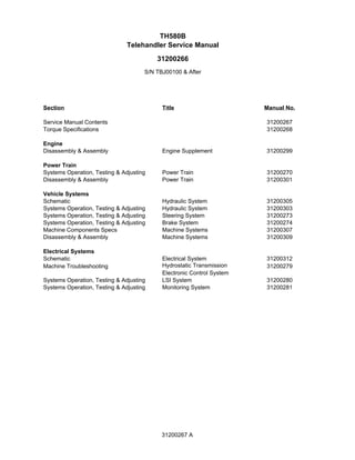
1. Section Title Manual No.
Service Manual Contents 31200267
Torque Specifications 31200268
Engine
Disassembly & Assembly Engine Supplement 31200299
Power Train
Systems Operation, Testing & Adjusting Power Train 31200270
Disassembly & Assembly Power Train 31200301
Vehicle Systems
Schematic Hydraulic System 31200305
Systems Operation, Testing & Adjusting Hydraulic System 31200303
Systems Operation, Testing & Adjusting Steering System 31200273
Systems Operation, Testing & Adjusting Brake System 31200274
Machine Components Specs Machine Systems 31200307
Disassembly & Assembly Machine Systems 31200309
Electrical Systems
Schematic Electrical System 31200312
Machine Troubleshooting Hydrostatic Transmission
Electronic Control System
31200279
Systems Operation, Testing & Adjusting LSI System 31200280
Systems Operation, Testing & Adjusting Monitoring System 31200281
TH580B
Telehandler Service Manual
S/N TBJ00100 & After
31200266
31200267 A
2. 31200299 3
Disassembly and Assembly Section
Disassembly and
Assembly Section
Battery - Remove and Install
Removal Procedure
Start By:
a. If equipped, turn the battery disconnect switch to the OFF
position. Refer to Operation and Maintenance Manual,
"Battery Disconnect Switch (if equipped) ".
Batteries give off flammable fumes that can
explode resulting in personal injury.
Prevent sparks near the batteries. They could
cause vapors to explode. Do not allow the jump
start cable ends to contact each other or the
machine.
Do not smoke when checking battery electrolyte
levels.
Electrolyte is an acid and can cause personal
injury if it contacts skin or eyes.
Always wear eye protection when starting a
machine with jump start cables.
Improper jump start procedures can cause an
explosion resulting in personal injury.
Always connect the positive (+) to positive (+) and
the negative (-) to negative (-).
Jump start only with an energy source with the
same voltage as the stalled machine.
Turn off all lights and accessories on the stalled
machine. Otherwise, they will operate when the
energy source is connected.
Illustration 1 g00909832
1. The following procedure shows the removal of the
front battery which is an attachment. Use the same
procedure when you are removing the rear battery.
Illustration 2 g00909220
2. Pull back the terminal cover (1) in order to
disconnect positive cable (2). Pull back the
terminal cover (3) in order to disconnect negative
cable (4).
Illustration 3 g00909235
3. Remove nuts (5), the washers and hold down
bracket (6).
Illustration 4 g00909831
4. With the aid of a second person or with the aid of
a suitable lifting device, remove battery (7). The
weight of the battery is approximately 25 kg (55 lb).
Remove studs (8).
3. 4 31200299
Disassembly and Assembly Section
Installation Procedure
Illustration 5 g00909832
1. The following procedure shows the installation of
the front battery which is an attachment. Use the
same procedure when you are installing the rear
battery.
Illustration 6 g00909831
2. Install studs (8). With the aid of a second person
or with the aid of a suitable lifting device, install
battery (7). The weight of the battery is
approximately 25 kg (55 lb).
Illustration 7 g00909235
3. Install hold down bracket (6), nuts (5), and the
washers.
Illustration 8 g00909220
4. Connect positive cable (2) and slide terminal cover
(1) into position. Connect Negative cable (4) and
slide terminal cover (3) into position.
End By:
a. If equipped, turn the battery disconnect switch to the ON
position. Refer to Operation and Maintenance Manual,
"Battery Disconnect Switch (if equipped)".
Alternator - Remove and Install
Removal Procedure
Start By:
a. Turn the battery disconnect switch to the OFF position.
Refer to Operation and Maintenance Manual, "Battery
Disconnect Switch (if equipped)". If the machine is not
equipped with a battery disconnect switch, disconnect
the battery cables from the battery and insulate the
battery clamps.
1. Put identification marks on all wires for installation
purposes.
Illustration 9 g00908444
2. Remove belt (1) from alternator (2). Refer to
Operation and maintenance Manual, "Belts -
Inspect/Adjust/Replace".
3. Disconnect wires (3) and positive cable (4).
4. Remove bolt (5), the washer, nut (6), bolt (7) and
the washers before removing alternator (2) from
the machine.
4. 31200299 5
Disassembly and Assembly Section
Installation Procedure
1. Clean all parts and inspect all parts. If any parts are
worn or damaged, use new Caterpillar parts for
replacement.
Illustration 10 g00908444
2. Position alternator (2) onto the machine. Install
bolt (7), nut (6) and washers. Install bolt (5) and
the washer.
3. Connect wires (3) and positive cable (4) to
alternator (2).
4. Install belt (1) from alternator (2). Refer to
Operation and maintenance Manual, "Belts -
Inspect/Adjust/Replace".
End By:
a. Turn the battery disconnect switch to the ON position.
Refer to Operation and Maintenance Manual, "Battery
Disconnect Switch (if equipped)". If the machine is not
equipped with a battery disconnect switch and the
battery was disconnected, remove the insulation from
the battery clamps and install the battery cables onto the
battery.
Electric Starting Motor -Remove
and Install
Removal Procedure
Accidental machine starting can cause injury or
death to personnel working on the machine.
To avoid accidental machine starting, turn the battery
disconnect switch to the OFF position and remove
the key. If the machine is not equipped with a battery
disconnect switch, disconnect the battery cables
from the battery and tape the battery clamps.
Place a do not operate tag at the battery disconnect
switch location to inform personnel that the
machine is being worked on.
1. Put identification marks on all wires for installation
purposes.
Illustration 11 g00908447
2. Disconnect positive cable (2) from starter motor (1).
Lift the plastic cap (not shown) in order to access
screw (3) and disconnect wire (4).
Illustration 12 g00908460
3. Remove bolt (5) in order to disconnect ground
cable (6).
4. Remove bolts (7) and remove starter motor (1)
from the engine.
Installation Procedure
1. Clean all parts and inspect all parts. If any parts are
worn or damaged, use new Caterpillar parts for
replacement.
5. 6 31200299
Disassembly and Assembly Section
Illustration 13 g00908460
2. Position starter motor (1) onto the engine and
install bolts (7).
3. Position ground cable (6) and install bolt (5).
Illustration 14 g00908447
4. Install screw (3) in order to connect wire (4). Close
the plastic cap (not shown). Connect positive cable
(2) to starter motor (1).
End By:
a. Turn the battery disconnect switch to the ON position.
Refer to Operation and Maintenance Manual, "Battery
Disconnect Switch (if equipped)". If the machine is not
equipped with a battery disconnect switch and the
battery was disconnected, remove the insulation from
the battery clamps and install the battery cables onto the
battery.
Air Cleaner - Remove
Removal Procedure
Illustration 15 g00909117
1. Disconnect inlet duct (2) from air cleaner assembly
(1).
Illustration 16 g00909118
2. Remove hose clamp (3) and disconnect inlet hose
(4) from air cleaner assembly (1).
Illustration 17 g00909119
3. Disconnect hose (5) from air cleaner assembly (1).
6. 31200299 7
Disassembly and Assembly Section
Illustration 18 g00909120
Illustration 19 g00909121
4. Remove nuts (6), bolts (7) and the washers
before removing air cleaner assembly (1) from the
engine.
Air Cleaner - Install
Installation Procedure
1. Clean all parts and inspect all parts. If any parts are
worn or damaged, use new Caterpillar parts for
replacement.
Illustration 20 g00909122
Illustration 21 g00909123
2. Position air cleaner assembly (1) on the engine and
install bolts (7), nuts (6) and the washers.
Illustration 22 g00909124
3. Connect hose (5) to air cleaner assembly (1).
Illustration 23 g00909125
4. Connect inlet hose (4) to air cleaner assembly (1)
and install hose clamp (3).
7. 8 31200299
Disassembly and Assembly Section
Illustration 24 g00909126
5. Connect inlet duct (2) to air cleaner assembly (1).
Muffler - Remove and Install
Removal Procedure
Hot oil and components can cause personal injury.
Do not allow hot oil or components to contact
skin.
Illustration 25 g00914593
1. Remove bolts (1) and the washers in order to
remove cover (2) and exhaust shield (3).
Illustration 26 g00914594
The photograph is from the top side of the muffler
2. Remove clamp (4) which connects exhaust pipe (5)
to muffler (6).
Illustration 27 g00914595
Illustration 28 g00914606
3. Remove bolts (7) and the washers before sliding
muffler (6) away from exhaust pipe (5). Remove the
muffler from the machine.
Installation Procedure
Illustration 29 g00914606
8. 31200299 9
Disassembly and Assembly Section
Illustration 30 g00914595
1. Position muffler (6) and then slide the muffler onto
exhaust pipe (5) before installing bolts (7) and the
washers.
Illustration 31 g00914594
The photograph is from the top side of the muffler.
2. Install clamp (4) which connects exhaust pipe (5) to
muffler (6).
Illustration 32 g00914593
3. Position exhaust shield (3) with cover (2) and
install bolts (1) with the washers.
Expansion Tank - Remove and
Install
Removal Procedure
At operating temperature, the engine coolant is hot
and under pressure.
Steam can cause personal injury.
Check the coolant level only after the engine has
been stopped and the fill cap is cool enough to
touch with your bare hand.
Remove the fill cap slowly to relieve pressure.
Cooling system conditioner contains alkali. Avoid
contact with the skin and eyes to prevent personal
injury.
NOTICE
Care must be taken to ensure that fluids are contained
during performance of inspection, maintenance, testing,
adjusting and repair of the product. Be prepared to collect
the fluid with suitable containers before opening any
compartment or disassembling any component
containing fluids.
Dispose of all fluids according to local regulations and
mandates.
1. Drain the coolant from the radiator into a suitable
container so that the level of the coolant in the
radiator is below the level of the expansion tank.
The capacity of the cooling system is
approximately 27.5 L (7.3 US gal). Refer to the
appropriate Operation and Maintenance Manual.
Illustration 33 g00914256
2. Loosen the hose clamp and disconnect hose (6)
from expansion tank (3).
3. Disconnect hose (4) from filler cap (5).
9. 10 31200299
Disassembly and Assembly Section
Illustration 34 g00914264
4. Loosen the hose clamps and disconnect hose (1)
and hose (2) from expansion tank (3).
5. Remove bolts (7) and the washers in order to
remove expansion tank (3).
Installation Procedure
Illustration 35 g00914264
1. Position expansion tank (3) and install bolts (7)
and the washers.
2. Connect hose (6) to expansion tank (3) and
tighten the hose clamp.
Illustration 36 g00914256
3. Disconnect hose (4) from filler cap (5).
4. Connect hose (1) and hose (2) to expansion tank
(3) and tighten the hose clamps.
5. Fill the cooling system. The capacity of the cooling
system is approximately 27.5 L (7.3 US gal).
Refer to the appropriate Operation and
Maintenance Manual.
Radiator - Remove
Removal Procedure
Start By:
a. Remove the access plate.
At operating temperature, the engine coolant is hot
and under pressure.
Steam can cause personal injury.
Check the coolant level only after the engine has
been stopped and the fill cap is cool enough to
touch with your bare hand.
Remove the fill cap slowly to relieve pressure.
Cooling system conditioner contains alkali. Avoid
contact with the skin and eyes to prevent personal
injury.
NOTICE
Care must be taken to ensure that fluids are contained
during performance of inspection, maintenance, testing,
adjusting and repair of the product. Be prepared to collect
the fluid with suitable containers before opening any
compartment or disassembling any component
containing fluids.
Dispose of all fluids according to local regulations and
mandates.
1. Put identification marks on all hoses for installation
purposes. Plug all hoses. This helps to prevent
fluid loss, and this helps to keep contaminants
from entering the system.
2. Drain the coolant from the cooling system into a
suitable container for storage or disposal. The
capacity of the cooling system is approximately
27.5 L (7.3 US gal). Refer to the appropriate
Operation and Maintenance Manual.
10. 31200299 11
Disassembly and Assembly Section
Illustration 37 g00912426
3. If equipped, release latch (1) in order to remove
condenser (2) from radiator (3). Tilt the condenser
and remove the condenser from the mounts at the
base of the radiator. Move the condenser aside.
Note: Do not disconnect the hose to the condenser.
The radiator can be removed without discharging the
refrigerant.
Illustration 38 g00912772
4. Loosen the hose clamp and disconnect hose (top)
(4) from radiator (3).
Illustration 39 g00912773
5. Loosen the hose clamp and disconnect hose
(bottom) (5) from the radiator.
Illustration 40 g00912779
6. Loosen the hose clamp and disconnect hose (6)
from radiator (3).
Illustration 41 g00912775
7. Remove bolts (7) and the washer from both sides
of shroud (8).
Illustration 42 g00912780
8. Remove bolts (9), the washers, bolt (10), the
washer and mount (11) in order to remove bracket
(12) from radiator (3) and the chassis.
11. 12 31200299
Disassembly and Assembly Section
Illustration 43 g00912781
9. Remove bolt (13), the washers, mount (14), bolt
(15) and the washer in order to remove bracket
(16) from radiator (3) and the chassis.
Illustration 44 g00912782
10. Remove bolts (17), the washers and the nuts that
secure radiator (3) to the chassis.
11. With the aid of a second person, remove radiator
(3) from the machine.
Illustration 45 g00912783
12. Remove mounts (18) from the chassis.
Radiator - Disassemble
Disassembly Procedure
Start By:
a. Remove the radiator from the machine. Refer to
Disassembly and Assembly, "Radiator - Remove".
Illustration 46 g00913571
1. Remove bolts (1) and the washers in order to
remove bracket (2) from radiator (3).
Illustration 47 g00913572
2. Remove bolts (4) and the washers in order to
remove bracket (5) from radiator (3).
Illustration 48 00913575
12. 31200299 13
Disassembly and Assembly Section
3. Remove bolts (6) and the washers in order to
remove mounting bracket (7) from radiator core
(3).
4. Remove bolts (8) and the washers in order to
remove mounting bracket (9) from radiator core
(3).
Radiator - Assemble
Assembly Procedure
Illustration 49 00913593
1. Position mounting bracket (9) onto radiator (3) and
install bolts (8) with the washers.
2. Position mounting bracket (7) onto radiator (3) and
install bolts (6) with the washers.
Illustration 50 g00913594
3. Position bracket (5) onto the front of radiator (3)
and install bolts (4) with the washers.
Illustration 51 g00913595
4. Position bracket (2) onto the front of radiator (3)
and install bolts (1) with the washers.
End By:
a. Install the radiator onto the machine. Refer to
Disassembly and Assembly, "Radiator - Install".
Radiator - Install
Installation Procedure
1. Clean all parts and inspect all parts. If any parts are
worn or damaged, use new Caterpillar parts for
replacement.
Illustration 52 g00912841
2. Install mounts (18) into the chassis.
Illustration 53 g00912843
13. 14 31200299
Disassembly and Assembly Section
3. With aid of a second person, lift radiator (3) into
position. Install bolts (17), the washers and the nuts
that secure the radiator to the chassis.
Illustration 54 g00912846
4. Install bolt (13), the washer, mount (14), bolt (15)
and the washer in order to secure bracket (16) to
radiator (3) and the chassis.
Illustration 55 g00912848
5. Install bolts (9), the washer, bolt (10), the washer
and mount (11) in order to secure bracket (12) to
radiator (3) and the chassis.
Illustration 56 g00912849
6. Install bolts (7) and the washers into both sides of
shroud (8).
Illustration 57 g00912853
7. Connect hose (6) to radiator (3) and tighten the
hose clamp.
Illustration 58 g00912861
8. Connect hose (bottom) (5) to radiator (3) and
tighten the hose clamp.
Illustration 59 g00912860
9. Connect hose (top) (4) to radiator (3) and tighten
the hose clamp.
14. 31200299 15
Disassembly and Assembly Section
Illustration 60 g00912875
10. If equipped, Install condenser (2) into the mounts
at the base of radiator (3) before you fasten latch
(1).
11. Fill the cooling system. The capacity of the cooling
system is approximately 27.5 L (7.3 US gal).
Refer to the appropriate Operation and
Maintenance Manual.
End By:
a. Install the access plate.
Fan Guard - Remove and Install
Removal Procedure
Illustration 61 g00909977
1. Remove bolts (1) and the washers in order to
remove fan guard (2) from shroud (3).
Installation Procedure
Illustration 62 g00909977
1. Position fan guard (2) on shroud (3) and install
bolts (1) and the washers.
Transmission Oil Cooler -
Remove
Removal Procedure
Start By:
a. Remove the access plate.
Personal injury can result from hydraulic oil
pressure and hot oil.
Hydraulic oil pressure can remain in the hydraulic
system after the engine has been stopped. Serious
injury can be caused if this pressure is not released
before any service is done on the hydraulic system.
Make sure all of the attachments have been
lowered, oil is cool before removing any
components or lines. Remove the oil filler cap only
when the engine is stopped, and the filler cap is cool
enough to touch with your bare hand.
At operating temperature, the engine coolant is hot
and under pressure.
Steam can cause personal injury.
15. 16 31200299
Disassembly and Assembly Section
Check the coolant level only after the engine has
been stopped and the fill cap is cool enough to
touch with your bare hand.
Remove the fill cap slowly to relieve pressure.
Cooling system conditioner contains alkali. Avoid
contact with the skin and eyes to prevent personal
injury.
NOTICE
Care must be taken to ensure that fluids are contained
during performance of inspection, maintenance, testing,
adjusting and repair of the product. Be prepared to collect
the fluid with suitable containers before opening any
compartment or disassembling any component
containing fluids.
Dispose of all fluids according to local regulations and
mandates.
1. Put Identification marks on all hoses for installation
purposes. Plug all hoses. This helps to prevent
fluid loss, and this helps to keep contaminants
from entering the system.
2. Drain the coolant from the cooling system into a
suitable container for storage or disposal. The
capacity of the cooling system is approximately
27.5 L (7.3 US gal). Refer to the appropriate
Operation and Maintenance Manual.
Illustration 63 g00910188
3. From the underside of the machine, loosen the
hose clamps and disconnect hoses (1) from oil
cooler (2).
4. Loosen the hose clamps and disconnect hoses
(3) from oil cooler (2).
5. Remove bolts (4) and the washer in order to
remove oil cooler (2) from the machine.
Transmission Oil Cooler -Install
Installation Procedure
Oil Cooler (High Ambient Temperature
Cooling Arrangement)
Note: The following procedure will give additional
information that is required to install an oil cooler for the
high ambient temperature cooling arrangement.
Remove Components
Illustration 64 g00987113
1. Loosen the hose clamp and remove hose (1) from
radiator (2).
2. Remove all hose clips and any cable straps which
secure hose (3).
3. Loosen the hose clamp and disconnect hose (3)
from water pump (4).
4. Loosen the hose clamp and disconnect hose (3)
from expansion tank (5) before removing the hose
from the machine.
Install Components
Illustration 65 g00987125
1. The following steps show the location of all hoses to
be installed with the high ambient temperature
cooling arrangement. Refer to Parts Manual, "Lines
16. 31200299 17
Disassembly and Assembly Section
Gp - Coolant" for the part numbers for all
components.
2. Connect a new hose (3) to expansion tank (5) and
tighten the hose clamp.
3. Connect hose (3) to water pump (4) and tighten
the hose clamp.
4. Install all hose clips and any cable straps which
secure hose (3).
Note: A new hose clamp (6) is installed as part of the
installation procedure for the oil cooler. Refer to
Disassembly and Assembly, "Transmission Oil Cooler -
Install".
5. Connect a new hose (1) to radiator (2).
Note: A new hose clamp (6) is installed as part of the
installation procedure for the oil cooler. Refer to
Disassembly and Assembly, "Transmission Oil Cooler -
Install".
Transmission Oil Cooler
1. Clean all parts and inspect all parts. If any parts are
worn or damaged, use new Caterpillar parts for
replacement.
Illustration 66 g00910194
2. At the underside of the machine, position oil cooler
(2) and install bolts (4) and the washers.
3. Connect hoses (3) and tighten the hose clamps.
4. Connect hoses (1) and tighten the hose clamps.
5. Fill the cooling system. The capacity of the cooling
system is approximately 27.5 L (7.3 US gal).
Refer to the appropriate Operation and
Maintenance Manual.
Refrigerant Condenser -
Remove and Install
Removal Procedure
Personal injury can result from contact with
refrigerant.
Contact with refrigerant can cause frost bite. Keep
face and hands away to help prevent injury.
Protective goggles must always be worn when
refrigerant lines are opened, even if the gauges
indicate the system is empty of refrigerant.
Always use precaution when a fitting is removed.
Slowly loosen the fitting. If the system is still under
pressure, release it slowly in a well ventilated area.
Personal injury or death can result from inhaling
refrigerant through a lit cigarette.
Inhaling air conditioner refrigerant gas through a lit
cigarette or other smoking method or inhaling
fumes released from a flame contacting air
conditioner refrigerant gas, can cause bodily harm
or death.
Do not smoke when servicing air conditioners or
wherever refrigerant gas may be present.
Use a certified recovery and recycling cart to properly
remove the refrigerant from the air conditioning
system.
1. Recover the air conditioner refrigerant from the air
conditioner system. The correct charge is 0.8 kg
(1.8 lb).
Illustration 67 g00910214
2. Disconnect two hoses (1) from condenser (2).
17. 18 31200299
Disassembly and Assembly Section
Illustration 68 g00910954
Illustration 69 g00910955
3. Release latch assembly (3). Tilt condenser (2)
toward the front of the machine before removing the
condenser.
Installation Procedure
Illustration 70 g00945940
Illustration 71 g00910954
1. Install condenser (2) into mount (4). Tilt the
condenser toward the rear of the machine and
fasten latch assembly (3).
Illustration 72 g00910214
2. Connect two hoses (1) to condenser (2).
3. Charge the air conditioner system. The correct
charge is 0.8 kg (1.8 lb).
18. 31200299 19
Disassembly and Assembly Section
Refrigerant Compressor -
Remove and Install
Removal Procedure
Start By:
a. Recover the air conditioner refrigerant from the air
conditioner system. The correct charge is 0.8 kg
(1.8 lb).
b. Remove the air cleaner. Refer to Disassembly and
Assembly, "Air Cleaner - Remove".
c. Remove the fan drive belt. Refer to
Operation and Maintenance Manual, "Belts -
Inspect/Adjust/Replace".
Personal injury can result from contact with
refrigerant.
Contact with refrigerant can cause frost bite. Keep
face and hands away to help prevent injury.
Protective goggles must always be worn when
refrigerant lines are opened, even if the gauges
indicate the system is empty of refrigerant.
Always use precaution when a fitting is removed.
Slowly loosen the fitting. If the system is still under
pressure, release it slowly in a well ventilated area.
Personal injury or death can result from inhaling
refrigerant through a lit cigarette.
Inhaling air conditioner refrigerant gas through a lit
cigarette or other smoking method or inhaling
fumes released from a flame contacting air
conditioner refrigerant gas, can cause bodily harm
or death.
Do not smoke when servicing air conditioners or
wherever refrigerant gas may be present.
Use a certified recovery and recycling cart to properly
remove the refrigerant from the air conditioning
system.
1. Put identification marks on all hose, on all tubes
and on all wires for installation purposes. Plug all
hoses and tubes. This helps prevent fluid loss, and
this helps to keep contaminants from entering the
system.
Illustration 73 g00921116
2. Remove bolt (1), the washers, the nut, the lower
half of mount (2) and plate (3). This will enable
access to the rear of refrigerant compressor (4).
Illustration 74 g00921516
3. Disconnect two tubes (5) from refrigerant
compressor (4).
Illustration 75 g00921517
4. Disconnect harness (6) from refrigerant
compressor (4).
5. Remove four bolts (7) and the washers in order
to remove refrigerant compressor (4) from the
machine.
Installation Procedure
1. Clean all parts and inspect all parts. If any parts are
worn or damaged, use new Caterpillar parts for
replacement.
19. Thank you very much for
your reading. Please Click
Here. Then Get COMPLETE
MANUAL. NO WAITING
NOTE:
If there is no response to
click on the link above,
please download the PDF
document first and then
click on it.
20. 20 31200299
Disassembly and Assembly Section
Illustration 76 g00921517
2. Position refrigerant compressor (4) onto the
machine and install four bolts (7) and the washers.
3. Connect harness (6) for refrigerant compressor
(4).
Illustration 77 g00921516
4. Connect two tubes (5) to refrigerant compressor
(4).
Illustration 78 g00921116
5. Position the lower half of mount (2) and plate (3)
before installing bolts (1), the washers and the nut.
Tighten the nut and the bolt to a torque of 775 ± 20
Nm (572 ± 15 lb ft).
End By:
a. Install the fan drive belt. Refer to Operation
and Maintenance Manual, "Belts -
Inspect/Adjust/Replace".
b. Install the air cleaner. Refer to Disassembly and
Assembly, "Air Cleaner- Install".
c. Charge the air conditioner system. The correct
charge is 0.8 kg (1.8 lb).
Engine Mount (Front) - Remove
Removal Procedure
Start By:
a. Remove the hood and the rear cover panel. Refer to
Disassembly and Assembly, "Engine Enclosure - Remove
and Install".
Personal injury or death can result from improper
lifting or blocking.
When a hoist or jack is used to lift any part or
component, stand clear of the area. Be sure the
hoist or jack has the correct capacity to lift a
component. Install blocks or stands before
performance of any work under a heavy
component.
Approximate weights of the components are
shown. Clean all surfaces where parts are to be
installed.
1. The following procedure is used to remove the
engine mount from the right side of the machine.
Use the same procedure to remove the engine
mount from the left side of the machine.
Illustration 79 g00921569
2. Remove bolt (1), the washers, the nut, the lower
half of mount (2) and washers (3).
21. 31200299 21
Disassembly and Assembly Section
Illustration 80 g00921570
Illustration 81 g00921670
3. Attach a suitable lifting chain to the bracket on the
rear side of the engine and to a suitable hoist.
4. Use the hoist to carefully lift the engine until
bracket (4) is just clear of the upper half of mount
(2).
5. Remove four nuts (5) and the washers in order to
remove mounting bracket (4) from engine block
(6).
Illustration 82 g00921668
6. Remove the upper half of mount (2) from chassis
(7).
Engine Mount (Front) - Install
Installation Procedure
1. The following procedure is used to install the
engine mount on the right side of the machine.
Use the same procedure to install the engine
mount on the left side of the machine.
2. Clean all parts and inspect all parts. If any parts
are worn or damaged, use new Caterpillar parts
for replacement.
Illustration 83 g00921905
3. The engine is supported by a suitable hoist and
suitable lifting chain. Refer to Disassembly and
Assembly, "Engine Mount (Front) - Remove".
Illustration 84 g00921904
4. Install the upper half of mount (2) into chassis (7).
Illustration 85 g00921906
22. 22 31200299
Disassembly and Assembly Section
5. Position mounting bracket (4) onto engine block
(6) and install four nuts (5) and the washers.
6. Use the hoist and lower the engine and bracket
(4) onto the upper half of mount (2). Remove the
hoist and lifting chain.
Illustration 86 g00921907
7. Install the lower half of mount (2), washers (3), bolt
(1), the washer and the nut. Tighten the bolt to a
torque of 220 ± 20 Nm (162 ± 15 lb ft).
End By:
a. Install the hood and the rear cover panel. Refer to
Disassembly and Assembly, "Engine Enclosure -
Remove and Install".
Engine Mount (Rear) - Remove
Removal Procedure
Start By:
a. Remove the hood. Refer to Disassembly and
Assembly, "Engine Enclosure - Remove and
Install".
b. Remove the air cleaner. Refer to Disassembly and
Assembly, "Air Cleaner - Remove".
Personal injury or death can result from improper
lifting or blocking.
When a hoist or jack is used to lift any part or
component, stand clear of the area. Be sure the
hoist or jack has the correct capacity to lift a
component. Install blocks or stands before
performance of any work under a heavy
component.
Approximate weights of the components are
shown. Clean all surfaces where parts are to be
installed.
Illustration 87 g00984274
1. Attach a suitable lifting chain to the bracket on the
engine and to a suitable hoist. Take up the tension
on the chain but do not try to lift the engine at this
time.
Illustration 88 g00984278
Illustration 89 g00984279
2. Remove bolt (1), two washers (2), nut (3), washer
(4), the lower half of mount (5) and sleeve (6).
3. Use the hoist to carefully lift the engine and the
transmission until bracket (7) is just clear of the
upper half of mount (5). The combined weight of
the engine and the transmission is approximately
780 kg (1720 lb).
4. Remove four bolts (8) and the washers in order
to remove bracket (7). Remove the upper half of
mount (5) from the engine frame.