This document contains sections from a service manual for telehandlers, including:
1. Procedures for removing and installing components like the battery, alternator, starter motor, air cleaner, muffler, expansion tank, and radiator.
2. Steps for disassembling and assembling the radiator.
3. Safety information is provided throughout regarding handling fluids, hot components, and preventing accidental starting of equipment.
Komatsu PC1800-6 Hydraulic Excavator Service Repair Manual (SN: 11002 and up)dfujsjjekme
This is the Highly Detailed factory service repair manual for theKOMATSU PC1800-6 HYDRAULIC EXCAVATOR, this Service Manual has detailed illustrations as well as step by step instructions,It is 100 percents complete and intact. they are specifically written for the do-it-yourself-er as well as the experienced mechanic.KOMATSU PC1800-6 HYDRAULIC EXCAVATOR Service Repair Workshop Manual provides step-by-step instructions based on the complete dis-assembly of the machine. It is this level of detail, along with hundreds of photos and illustrations, that guide the reader through each service and repair procedure. Complete download comes in pdf format which can work under all PC based windows operating system and Mac also, All pages are printable. Using this repair manual is an inexpensive way to keep your vehicle working properly.
Include:
Komatsu PC1800-6 Hydraulic Excavator Shop Manual
Komatsu PC1800-6 Hydraulic Excavator Operation and Maintenance Manual
Komatsu PC1800-6 Hydraulic Excavator Field Assembly Manual
Models and Serial Numbers:
Komatsu PC1800-6 Hydraulic Excavator --- 10011 and up
Komatsu PC1800-6 Hydraulic Excavator --- 11002 and up
Shop Manual Covers:
General
Structure, Function and Maintenance Standard
Testing and Adjusting
Disassembly and Assembly
Others
Operation and Maintenance Manual Covers:
Safety
Operation
Maintenance
Specifications
Attachments and Options
Loading Shovel
Index
Field Assembly Manual Covers:
General
Components to be Assembled in Harbor
Assembly of Chassis
Pc1800 Installation of Backhoe Work Equipment
Assembly Manual for Loading Shovel Work Equipment
Inspection and Servicing Procedures after Finnishing all the Assembly and Installation Works
Initialization procedures for VHMS controller
Setting procedures for replacing VHMS controller
Field assembly inspection report
File Format: PDF
Compatible: All Versions of Windows & Mac
Language: English
Requirements: Adobe PDF Reader
NO waiting, Buy from responsible seller and get INSTANT DOWNLOAD, Without wasting your hard-owned money on uncertainty or surprise! All pages are is great to haveKOMATSU PC1800-6 HYDRAULIC EXCAVATOR Service Repair Workshop Manual.
Thanks for visiting!
Komatsu PC1800-6 Hydraulic Excavator Service Repair Manual (SN: 10011 and up)dfujsjjekme
This is the Highly Detailed factory service repair manual for theKOMATSU PC1800-6 HYDRAULIC EXCAVATOR, this Service Manual has detailed illustrations as well as step by step instructions,It is 100 percents complete and intact. they are specifically written for the do-it-yourself-er as well as the experienced mechanic.KOMATSU PC1800-6 HYDRAULIC EXCAVATOR Service Repair Workshop Manual provides step-by-step instructions based on the complete dis-assembly of the machine. It is this level of detail, along with hundreds of photos and illustrations, that guide the reader through each service and repair procedure. Complete download comes in pdf format which can work under all PC based windows operating system and Mac also, All pages are printable. Using this repair manual is an inexpensive way to keep your vehicle working properly.
Include:
Komatsu PC1800-6 Hydraulic Excavator Shop Manual
Komatsu PC1800-6 Hydraulic Excavator Operation and Maintenance Manual
Komatsu PC1800-6 Hydraulic Excavator Field Assembly Manual
Models and Serial Numbers:
Komatsu PC1800-6 Hydraulic Excavator --- 10011 and up
Komatsu PC1800-6 Hydraulic Excavator --- 11002 and up
Shop Manual Covers:
General
Structure, Function and Maintenance Standard
Testing and Adjusting
Disassembly and Assembly
Others
Operation and Maintenance Manual Covers:
Safety
Operation
Maintenance
Specifications
Attachments and Options
Loading Shovel
Index
Field Assembly Manual Covers:
General
Components to be Assembled in Harbor
Assembly of Chassis
Pc1800 Installation of Backhoe Work Equipment
Assembly Manual for Loading Shovel Work Equipment
Inspection and Servicing Procedures after Finnishing all the Assembly and Installation Works
Initialization procedures for VHMS controller
Setting procedures for replacing VHMS controller
Field assembly inspection report
File Format: PDF
Compatible: All Versions of Windows & Mac
Language: English
Requirements: Adobe PDF Reader
NO waiting, Buy from responsible seller and get INSTANT DOWNLOAD, Without wasting your hard-owned money on uncertainty or surprise! All pages are is great to haveKOMATSU PC1800-6 HYDRAULIC EXCAVATOR Service Repair Workshop Manual.
Thanks for visiting!
This is the most complete Operation and Maintenance Manual for the KOMATSU PC1800-6 GALEO HYDRAULIC EXCAVATOR . Operation and Maintenance Manual can come in handy especially when you have to do immediate repair to your KOMATSU PC1800-6 GALEO HYDRAULIC EXCAVATOR .Operation and Maintenance Manual comes with comprehensive details regarding technical data. Diagrams a complete list of KOMATSU PC1800-6 GALEO HYDRAULIC EXCAVATOR parts and is a must for the will not be dissatisfied.
Model and Serial Number:
Komatsu PC1800-6 Galeo Hydraulic Excavator --- 11035 and up
Manual Covers:
Safety
Operation
Maintenance
Specifications
Attachments and options
Loading shovel
Index
File Format: PDF
Compatible: All Versions of Windows & Mac
Language: English
Requirements: Adobe PDF Reader
All pages are run off what you need & take it with you into the garage or save money $$ By doing your own repairs!These manuals make it easy for any skill level with these very easy to by step instructions!
Thanks for visiting!
Ever been troubled by the blinking sign and didn’t know what to do?
Here’s a handy guide to dashboard symbols so that you’ll never be confused again!
Save them for later and save the trouble!
Core technology of Hyundai Motor Group's EV platform 'E-GMP'Hyundai Motor Group
What’s the force behind Hyundai Motor Group's EV performance and quality?
Maximized driving performance and quick charging time through high-density battery pack and fast charging technology and applicable to various vehicle types!
Discover more about Hyundai Motor Group’s EV platform ‘E-GMP’!
What Does the PARKTRONIC Inoperative, See Owner's Manual Message Mean for You...Autohaus Service and Sales
Learn what "PARKTRONIC Inoperative, See Owner's Manual" means for your Mercedes-Benz. This message indicates a malfunction in the parking assistance system, potentially due to sensor issues or electrical faults. Prompt attention is crucial to ensure safety and functionality. Follow steps outlined for diagnosis and repair in the owner's manual.
Comprehensive program for Agricultural Finance, the Automotive Sector, and Empowerment . We will define the full scope and provide a detailed two-week plan for identifying strategic partners in each area within Limpopo, including target areas.:
1. Agricultural : Supporting Primary and Secondary Agriculture
• Scope: Provide support solutions to enhance agricultural productivity and sustainability.
• Target Areas: Polokwane, Tzaneen, Thohoyandou, Makhado, and Giyani.
2. Automotive Sector: Partnerships with Mechanics and Panel Beater Shops
• Scope: Develop collaborations with automotive service providers to improve service quality and business operations.
• Target Areas: Polokwane, Lephalale, Mokopane, Phalaborwa, and Bela-Bela.
3. Empowerment : Focusing on Women Empowerment
• Scope: Provide business support support and training to women-owned businesses, promoting economic inclusion.
• Target Areas: Polokwane, Thohoyandou, Musina, Burgersfort, and Louis Trichardt.
We will also prioritize Industrial Economic Zone areas and their priorities.
Sign up on https://profilesmes.online/welcome/
To be eligible:
1. You must have a registered business and operate in Limpopo
2. Generate revenue
3. Sectors : Agriculture ( primary and secondary) and Automative
Women and Youth are encouraged to apply even if you don't fall in those sectors.
Why Is Your BMW X3 Hood Not Responding To Release CommandsDart Auto
Experiencing difficulty opening your BMW X3's hood? This guide explores potential issues like mechanical obstruction, hood release mechanism failure, electrical problems, and emergency release malfunctions. Troubleshooting tips include basic checks, clearing obstructions, applying pressure, and using the emergency release.
5 Warning Signs Your BMW's Intelligent Battery Sensor Needs AttentionBertini's German Motors
IBS monitors and manages your BMW’s battery performance. If it malfunctions, you will have to deal with an array of electrical issues in your vehicle. Recognize warning signs like dimming headlights, frequent battery replacements, and electrical malfunctions to address potential IBS issues promptly.
In this presentation, we have discussed a very important feature of BMW X5 cars… the Comfort Access. Things that can significantly limit its functionality. And things that you can try to restore the functionality of such a convenient feature of your vehicle.
Things to remember while upgrading the brakes of your carjennifermiller8137
Upgrading the brakes of your car? Keep these things in mind before doing so. Additionally, start using an OBD 2 GPS tracker so that you never miss a vehicle maintenance appointment. On top of this, a car GPS tracker will also let you master good driving habits that will let you increase the operational life of your car’s brakes.
What Exactly Is The Common Rail Direct Injection System & How Does It WorkMotor Cars International
Learn about Common Rail Direct Injection (CRDi) - the revolutionary technology that has made diesel engines more efficient. Explore its workings, advantages like enhanced fuel efficiency and increased power output, along with drawbacks such as complexity and higher initial cost. Compare CRDi with traditional diesel engines and discover why it's the preferred choice for modern engines.
"Trans Failsafe Prog" on your BMW X5 indicates potential transmission issues requiring immediate action. This safety feature activates in response to abnormalities like low fluid levels, leaks, faulty sensors, electrical or mechanical failures, and overheating.
Symptoms like intermittent starting and key recognition errors signal potential problems with your Mercedes’ EIS. Use diagnostic steps like error code checks and spare key tests. Professional diagnosis and solutions like EIS replacement ensure safe driving. Consult a qualified technician for accurate diagnosis and repair.
𝘼𝙣𝙩𝙞𝙦𝙪𝙚 𝙋𝙡𝙖𝙨𝙩𝙞𝙘 𝙏𝙧𝙖𝙙𝙚𝙧𝙨 𝙞𝙨 𝙫𝙚𝙧𝙮 𝙛𝙖𝙢𝙤𝙪𝙨 𝙛𝙤𝙧 𝙢𝙖𝙣𝙪𝙛𝙖𝙘𝙩𝙪𝙧𝙞𝙣𝙜 𝙩𝙝𝙚𝙞𝙧 𝙥𝙧𝙤𝙙𝙪𝙘𝙩𝙨. 𝙒𝙚 𝙝𝙖𝙫𝙚 𝙖𝙡𝙡 𝙩𝙝𝙚 𝙥𝙡𝙖𝙨𝙩𝙞𝙘 𝙜𝙧𝙖𝙣𝙪𝙡𝙚𝙨 𝙪𝙨𝙚𝙙 𝙞𝙣 𝙖𝙪𝙩𝙤𝙢𝙤𝙩𝙞𝙫𝙚 𝙖𝙣𝙙 𝙖𝙪𝙩𝙤 𝙥𝙖𝙧𝙩𝙨 𝙖𝙣𝙙 𝙖𝙡𝙡 𝙩𝙝𝙚 𝙛𝙖𝙢𝙤𝙪𝙨 𝙘𝙤𝙢𝙥𝙖𝙣𝙞𝙚𝙨 𝙗𝙪𝙮 𝙩𝙝𝙚 𝙜𝙧𝙖𝙣𝙪𝙡𝙚𝙨 𝙛𝙧𝙤𝙢 𝙪𝙨.
Over the 10 years, we have gained a strong foothold in the market due to our range's high quality, competitive prices, and time-lined delivery schedules.
Caterpillar cat th360 b and th560b telehandler service repair manual sn tbp00100 and after
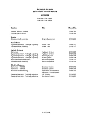
1. Section Title Manual No.
Service Manual Contents 31200265
Torque Specifications 31200268
Engine
Disassembly & Assembly Engine Supplement 31200299
Power Train
Systems Operation, Testing & Adjusting Power Train 31200270
Disassembly & Assembly Power Train 31200300
Vehicle Systems
Schematic Hydraulic System 31200304
Systems Operation, Testing & Adjusting Hydraulic System 31200302
Systems Operation, Testing & Adjusting Steering System 31200273
Systems Operation, Testing & Adjusting Brake System 31200274
Machine Components Specs Machine Systems 31200306
Disassembly & Assembly Machine Systems 31200308
Electrical Systems
Schematic - TH360B Electrical System 31200310
Schematic - TH560B Electrical System 31200311
Machine Troubleshooting Hydrostatic Transmission
Electronic Control System
31200279
Systems Operation, Testing & Adjusting LSI System 31200280
Systems Operation, Testing & Adjusting Monitoring System 31200281
TH360B & TH560B
Telehandler Service Manual
S/N TBH00100 & After
S/N TBP00100 & After
31200264
31200265 A
2. 31200299 3
Disassembly and Assembly Section
Disassembly and
Assembly Section
Battery - Remove and Install
Removal Procedure
Start By:
a. If equipped, turn the battery disconnect switch to the OFF
position. Refer to Operation and Maintenance Manual,
"Battery Disconnect Switch (if equipped) ".
Batteries give off flammable fumes that can
explode resulting in personal injury.
Prevent sparks near the batteries. They could
cause vapors to explode. Do not allow the jump
start cable ends to contact each other or the
machine.
Do not smoke when checking battery electrolyte
levels.
Electrolyte is an acid and can cause personal
injury if it contacts skin or eyes.
Always wear eye protection when starting a
machine with jump start cables.
Improper jump start procedures can cause an
explosion resulting in personal injury.
Always connect the positive (+) to positive (+) and
the negative (-) to negative (-).
Jump start only with an energy source with the
same voltage as the stalled machine.
Turn off all lights and accessories on the stalled
machine. Otherwise, they will operate when the
energy source is connected.
Illustration 1 g00909832
1. The following procedure shows the removal of the
front battery which is an attachment. Use the same
procedure when you are removing the rear battery.
Illustration 2 g00909220
2. Pull back the terminal cover (1) in order to
disconnect positive cable (2). Pull back the
terminal cover (3) in order to disconnect negative
cable (4).
Illustration 3 g00909235
3. Remove nuts (5), the washers and hold down
bracket (6).
Illustration 4 g00909831
4. With the aid of a second person or with the aid of
a suitable lifting device, remove battery (7). The
weight of the battery is approximately 25 kg (55 lb).
Remove studs (8).
3. 4 31200299
Disassembly and Assembly Section
Installation Procedure
Illustration 5 g00909832
1. The following procedure shows the installation of
the front battery which is an attachment. Use the
same procedure when you are installing the rear
battery.
Illustration 6 g00909831
2. Install studs (8). With the aid of a second person
or with the aid of a suitable lifting device, install
battery (7). The weight of the battery is
approximately 25 kg (55 lb).
Illustration 7 g00909235
3. Install hold down bracket (6), nuts (5), and the
washers.
Illustration 8 g00909220
4. Connect positive cable (2) and slide terminal cover
(1) into position. Connect Negative cable (4) and
slide terminal cover (3) into position.
End By:
a. If equipped, turn the battery disconnect switch to the ON
position. Refer to Operation and Maintenance Manual,
"Battery Disconnect Switch (if equipped)".
Alternator - Remove and Install
Removal Procedure
Start By:
a. Turn the battery disconnect switch to the OFF position.
Refer to Operation and Maintenance Manual, "Battery
Disconnect Switch (if equipped)". If the machine is not
equipped with a battery disconnect switch, disconnect
the battery cables from the battery and insulate the
battery clamps.
1. Put identification marks on all wires for installation
purposes.
Illustration 9 g00908444
2. Remove belt (1) from alternator (2). Refer to
Operation and maintenance Manual, "Belts -
Inspect/Adjust/Replace".
3. Disconnect wires (3) and positive cable (4).
4. Remove bolt (5), the washer, nut (6), bolt (7) and
the washers before removing alternator (2) from
the machine.
4. 31200299 5
Disassembly and Assembly Section
Installation Procedure
1. Clean all parts and inspect all parts. If any parts are
worn or damaged, use new Caterpillar parts for
replacement.
Illustration 10 g00908444
2. Position alternator (2) onto the machine. Install
bolt (7), nut (6) and washers. Install bolt (5) and
the washer.
3. Connect wires (3) and positive cable (4) to
alternator (2).
4. Install belt (1) from alternator (2). Refer to
Operation and maintenance Manual, "Belts -
Inspect/Adjust/Replace".
End By:
a. Turn the battery disconnect switch to the ON position.
Refer to Operation and Maintenance Manual, "Battery
Disconnect Switch (if equipped)". If the machine is not
equipped with a battery disconnect switch and the
battery was disconnected, remove the insulation from
the battery clamps and install the battery cables onto the
battery.
Electric Starting Motor -Remove
and Install
Removal Procedure
Accidental machine starting can cause injury or
death to personnel working on the machine.
To avoid accidental machine starting, turn the battery
disconnect switch to the OFF position and remove
the key. If the machine is not equipped with a battery
disconnect switch, disconnect the battery cables
from the battery and tape the battery clamps.
Place a do not operate tag at the battery disconnect
switch location to inform personnel that the
machine is being worked on.
1. Put identification marks on all wires for installation
purposes.
Illustration 11 g00908447
2. Disconnect positive cable (2) from starter motor (1).
Lift the plastic cap (not shown) in order to access
screw (3) and disconnect wire (4).
Illustration 12 g00908460
3. Remove bolt (5) in order to disconnect ground
cable (6).
4. Remove bolts (7) and remove starter motor (1)
from the engine.
Installation Procedure
1. Clean all parts and inspect all parts. If any parts are
worn or damaged, use new Caterpillar parts for
replacement.
5. 6 31200299
Disassembly and Assembly Section
Illustration 13 g00908460
2. Position starter motor (1) onto the engine and
install bolts (7).
3. Position ground cable (6) and install bolt (5).
Illustration 14 g00908447
4. Install screw (3) in order to connect wire (4). Close
the plastic cap (not shown). Connect positive cable
(2) to starter motor (1).
End By:
a. Turn the battery disconnect switch to the ON position.
Refer to Operation and Maintenance Manual, "Battery
Disconnect Switch (if equipped)". If the machine is not
equipped with a battery disconnect switch and the
battery was disconnected, remove the insulation from
the battery clamps and install the battery cables onto the
battery.
Air Cleaner - Remove
Removal Procedure
Illustration 15 g00909117
1. Disconnect inlet duct (2) from air cleaner assembly
(1).
Illustration 16 g00909118
2. Remove hose clamp (3) and disconnect inlet hose
(4) from air cleaner assembly (1).
Illustration 17 g00909119
3. Disconnect hose (5) from air cleaner assembly (1).
6. 31200299 7
Disassembly and Assembly Section
Illustration 18 g00909120
Illustration 19 g00909121
4. Remove nuts (6), bolts (7) and the washers
before removing air cleaner assembly (1) from the
engine.
Air Cleaner - Install
Installation Procedure
1. Clean all parts and inspect all parts. If any parts are
worn or damaged, use new Caterpillar parts for
replacement.
Illustration 20 g00909122
Illustration 21 g00909123
2. Position air cleaner assembly (1) on the engine and
install bolts (7), nuts (6) and the washers.
Illustration 22 g00909124
3. Connect hose (5) to air cleaner assembly (1).
Illustration 23 g00909125
4. Connect inlet hose (4) to air cleaner assembly (1)
and install hose clamp (3).
7. 8 31200299
Disassembly and Assembly Section
Illustration 24 g00909126
5. Connect inlet duct (2) to air cleaner assembly (1).
Muffler - Remove and Install
Removal Procedure
Hot oil and components can cause personal injury.
Do not allow hot oil or components to contact
skin.
Illustration 25 g00914593
1. Remove bolts (1) and the washers in order to
remove cover (2) and exhaust shield (3).
Illustration 26 g00914594
The photograph is from the top side of the muffler
2. Remove clamp (4) which connects exhaust pipe (5)
to muffler (6).
Illustration 27 g00914595
Illustration 28 g00914606
3. Remove bolts (7) and the washers before sliding
muffler (6) away from exhaust pipe (5). Remove the
muffler from the machine.
Installation Procedure
Illustration 29 g00914606
8. 31200299 9
Disassembly and Assembly Section
Illustration 30 g00914595
1. Position muffler (6) and then slide the muffler onto
exhaust pipe (5) before installing bolts (7) and the
washers.
Illustration 31 g00914594
The photograph is from the top side of the muffler.
2. Install clamp (4) which connects exhaust pipe (5) to
muffler (6).
Illustration 32 g00914593
3. Position exhaust shield (3) with cover (2) and
install bolts (1) with the washers.
Expansion Tank - Remove and
Install
Removal Procedure
At operating temperature, the engine coolant is hot
and under pressure.
Steam can cause personal injury.
Check the coolant level only after the engine has
been stopped and the fill cap is cool enough to
touch with your bare hand.
Remove the fill cap slowly to relieve pressure.
Cooling system conditioner contains alkali. Avoid
contact with the skin and eyes to prevent personal
injury.
NOTICE
Care must be taken to ensure that fluids are contained
during performance of inspection, maintenance, testing,
adjusting and repair of the product. Be prepared to collect
the fluid with suitable containers before opening any
compartment or disassembling any component
containing fluids.
Dispose of all fluids according to local regulations and
mandates.
1. Drain the coolant from the radiator into a suitable
container so that the level of the coolant in the
radiator is below the level of the expansion tank.
The capacity of the cooling system is
approximately 27.5 L (7.3 US gal). Refer to the
appropriate Operation and Maintenance Manual.
Illustration 33 g00914256
2. Loosen the hose clamp and disconnect hose (6)
from expansion tank (3).
3. Disconnect hose (4) from filler cap (5).
9. 10 31200299
Disassembly and Assembly Section
Illustration 34 g00914264
4. Loosen the hose clamps and disconnect hose (1)
and hose (2) from expansion tank (3).
5. Remove bolts (7) and the washers in order to
remove expansion tank (3).
Installation Procedure
Illustration 35 g00914264
1. Position expansion tank (3) and install bolts (7)
and the washers.
2. Connect hose (6) to expansion tank (3) and
tighten the hose clamp.
Illustration 36 g00914256
3. Disconnect hose (4) from filler cap (5).
4. Connect hose (1) and hose (2) to expansion tank
(3) and tighten the hose clamps.
5. Fill the cooling system. The capacity of the cooling
system is approximately 27.5 L (7.3 US gal).
Refer to the appropriate Operation and
Maintenance Manual.
Radiator - Remove
Removal Procedure
Start By:
a. Remove the access plate.
At operating temperature, the engine coolant is hot
and under pressure.
Steam can cause personal injury.
Check the coolant level only after the engine has
been stopped and the fill cap is cool enough to
touch with your bare hand.
Remove the fill cap slowly to relieve pressure.
Cooling system conditioner contains alkali. Avoid
contact with the skin and eyes to prevent personal
injury.
NOTICE
Care must be taken to ensure that fluids are contained
during performance of inspection, maintenance, testing,
adjusting and repair of the product. Be prepared to collect
the fluid with suitable containers before opening any
compartment or disassembling any component
containing fluids.
Dispose of all fluids according to local regulations and
mandates.
1. Put identification marks on all hoses for installation
purposes. Plug all hoses. This helps to prevent
fluid loss, and this helps to keep contaminants
from entering the system.
2. Drain the coolant from the cooling system into a
suitable container for storage or disposal. The
capacity of the cooling system is approximately
27.5 L (7.3 US gal). Refer to the appropriate
Operation and Maintenance Manual.
10. 31200299 11
Disassembly and Assembly Section
Illustration 37 g00912426
3. If equipped, release latch (1) in order to remove
condenser (2) from radiator (3). Tilt the condenser
and remove the condenser from the mounts at the
base of the radiator. Move the condenser aside.
Note: Do not disconnect the hose to the condenser.
The radiator can be removed without discharging the
refrigerant.
Illustration 38 g00912772
4. Loosen the hose clamp and disconnect hose (top)
(4) from radiator (3).
Illustration 39 g00912773
5. Loosen the hose clamp and disconnect hose
(bottom) (5) from the radiator.
Illustration 40 g00912779
6. Loosen the hose clamp and disconnect hose (6)
from radiator (3).
Illustration 41 g00912775
7. Remove bolts (7) and the washer from both sides
of shroud (8).
Illustration 42 g00912780
8. Remove bolts (9), the washers, bolt (10), the
washer and mount (11) in order to remove bracket
(12) from radiator (3) and the chassis.
11. 12 31200299
Disassembly and Assembly Section
Illustration 43 g00912781
9. Remove bolt (13), the washers, mount (14), bolt
(15) and the washer in order to remove bracket
(16) from radiator (3) and the chassis.
Illustration 44 g00912782
10. Remove bolts (17), the washers and the nuts that
secure radiator (3) to the chassis.
11. With the aid of a second person, remove radiator
(3) from the machine.
Illustration 45 g00912783
12. Remove mounts (18) from the chassis.
Radiator - Disassemble
Disassembly Procedure
Start By:
a. Remove the radiator from the machine. Refer to
Disassembly and Assembly, "Radiator - Remove".
Illustration 46 g00913571
1. Remove bolts (1) and the washers in order to
remove bracket (2) from radiator (3).
Illustration 47 g00913572
2. Remove bolts (4) and the washers in order to
remove bracket (5) from radiator (3).
Illustration 48 00913575
12. 31200299 13
Disassembly and Assembly Section
3. Remove bolts (6) and the washers in order to
remove mounting bracket (7) from radiator core
(3).
4. Remove bolts (8) and the washers in order to
remove mounting bracket (9) from radiator core
(3).
Radiator - Assemble
Assembly Procedure
Illustration 49 00913593
1. Position mounting bracket (9) onto radiator (3) and
install bolts (8) with the washers.
2. Position mounting bracket (7) onto radiator (3) and
install bolts (6) with the washers.
Illustration 50 g00913594
3. Position bracket (5) onto the front of radiator (3)
and install bolts (4) with the washers.
Illustration 51 g00913595
4. Position bracket (2) onto the front of radiator (3)
and install bolts (1) with the washers.
End By:
a. Install the radiator onto the machine. Refer to
Disassembly and Assembly, "Radiator - Install".
Radiator - Install
Installation Procedure
1. Clean all parts and inspect all parts. If any parts are
worn or damaged, use new Caterpillar parts for
replacement.
Illustration 52 g00912841
2. Install mounts (18) into the chassis.
Illustration 53 g00912843
13. 14 31200299
Disassembly and Assembly Section
3. With aid of a second person, lift radiator (3) into
position. Install bolts (17), the washers and the nuts
that secure the radiator to the chassis.
Illustration 54 g00912846
4. Install bolt (13), the washer, mount (14), bolt (15)
and the washer in order to secure bracket (16) to
radiator (3) and the chassis.
Illustration 55 g00912848
5. Install bolts (9), the washer, bolt (10), the washer
and mount (11) in order to secure bracket (12) to
radiator (3) and the chassis.
Illustration 56 g00912849
6. Install bolts (7) and the washers into both sides of
shroud (8).
Illustration 57 g00912853
7. Connect hose (6) to radiator (3) and tighten the
hose clamp.
Illustration 58 g00912861
8. Connect hose (bottom) (5) to radiator (3) and
tighten the hose clamp.
Illustration 59 g00912860
9. Connect hose (top) (4) to radiator (3) and tighten
the hose clamp.
14. 31200299 15
Disassembly and Assembly Section
Illustration 60 g00912875
10. If equipped, Install condenser (2) into the mounts
at the base of radiator (3) before you fasten latch
(1).
11. Fill the cooling system. The capacity of the cooling
system is approximately 27.5 L (7.3 US gal).
Refer to the appropriate Operation and
Maintenance Manual.
End By:
a. Install the access plate.
Fan Guard - Remove and Install
Removal Procedure
Illustration 61 g00909977
1. Remove bolts (1) and the washers in order to
remove fan guard (2) from shroud (3).
Installation Procedure
Illustration 62 g00909977
1. Position fan guard (2) on shroud (3) and install
bolts (1) and the washers.
Transmission Oil Cooler -
Remove
Removal Procedure
Start By:
a. Remove the access plate.
Personal injury can result from hydraulic oil
pressure and hot oil.
Hydraulic oil pressure can remain in the hydraulic
system after the engine has been stopped. Serious
injury can be caused if this pressure is not released
before any service is done on the hydraulic system.
Make sure all of the attachments have been
lowered, oil is cool before removing any
components or lines. Remove the oil filler cap only
when the engine is stopped, and the filler cap is cool
enough to touch with your bare hand.
At operating temperature, the engine coolant is hot
and under pressure.
Steam can cause personal injury.
15. 16 31200299
Disassembly and Assembly Section
Check the coolant level only after the engine has
been stopped and the fill cap is cool enough to
touch with your bare hand.
Remove the fill cap slowly to relieve pressure.
Cooling system conditioner contains alkali. Avoid
contact with the skin and eyes to prevent personal
injury.
NOTICE
Care must be taken to ensure that fluids are contained
during performance of inspection, maintenance, testing,
adjusting and repair of the product. Be prepared to collect
the fluid with suitable containers before opening any
compartment or disassembling any component
containing fluids.
Dispose of all fluids according to local regulations and
mandates.
1. Put Identification marks on all hoses for installation
purposes. Plug all hoses. This helps to prevent
fluid loss, and this helps to keep contaminants
from entering the system.
2. Drain the coolant from the cooling system into a
suitable container for storage or disposal. The
capacity of the cooling system is approximately
27.5 L (7.3 US gal). Refer to the appropriate
Operation and Maintenance Manual.
Illustration 63 g00910188
3. From the underside of the machine, loosen the
hose clamps and disconnect hoses (1) from oil
cooler (2).
4. Loosen the hose clamps and disconnect hoses
(3) from oil cooler (2).
5. Remove bolts (4) and the washer in order to
remove oil cooler (2) from the machine.
Transmission Oil Cooler -Install
Installation Procedure
Oil Cooler (High Ambient Temperature
Cooling Arrangement)
Note: The following procedure will give additional
information that is required to install an oil cooler for the
high ambient temperature cooling arrangement.
Remove Components
Illustration 64 g00987113
1. Loosen the hose clamp and remove hose (1) from
radiator (2).
2. Remove all hose clips and any cable straps which
secure hose (3).
3. Loosen the hose clamp and disconnect hose (3)
from water pump (4).
4. Loosen the hose clamp and disconnect hose (3)
from expansion tank (5) before removing the hose
from the machine.
Install Components
Illustration 65 g00987125
1. The following steps show the location of all hoses to
be installed with the high ambient temperature
cooling arrangement. Refer to Parts Manual, "Lines
16. 31200299 17
Disassembly and Assembly Section
Gp - Coolant" for the part numbers for all
components.
2. Connect a new hose (3) to expansion tank (5) and
tighten the hose clamp.
3. Connect hose (3) to water pump (4) and tighten
the hose clamp.
4. Install all hose clips and any cable straps which
secure hose (3).
Note: A new hose clamp (6) is installed as part of the
installation procedure for the oil cooler. Refer to
Disassembly and Assembly, "Transmission Oil Cooler -
Install".
5. Connect a new hose (1) to radiator (2).
Note: A new hose clamp (6) is installed as part of the
installation procedure for the oil cooler. Refer to
Disassembly and Assembly, "Transmission Oil Cooler -
Install".
Transmission Oil Cooler
1. Clean all parts and inspect all parts. If any parts are
worn or damaged, use new Caterpillar parts for
replacement.
Illustration 66 g00910194
2. At the underside of the machine, position oil cooler
(2) and install bolts (4) and the washers.
3. Connect hoses (3) and tighten the hose clamps.
4. Connect hoses (1) and tighten the hose clamps.
5. Fill the cooling system. The capacity of the cooling
system is approximately 27.5 L (7.3 US gal).
Refer to the appropriate Operation and
Maintenance Manual.
Refrigerant Condenser -
Remove and Install
Removal Procedure
Personal injury can result from contact with
refrigerant.
Contact with refrigerant can cause frost bite. Keep
face and hands away to help prevent injury.
Protective goggles must always be worn when
refrigerant lines are opened, even if the gauges
indicate the system is empty of refrigerant.
Always use precaution when a fitting is removed.
Slowly loosen the fitting. If the system is still under
pressure, release it slowly in a well ventilated area.
Personal injury or death can result from inhaling
refrigerant through a lit cigarette.
Inhaling air conditioner refrigerant gas through a lit
cigarette or other smoking method or inhaling
fumes released from a flame contacting air
conditioner refrigerant gas, can cause bodily harm
or death.
Do not smoke when servicing air conditioners or
wherever refrigerant gas may be present.
Use a certified recovery and recycling cart to properly
remove the refrigerant from the air conditioning
system.
1. Recover the air conditioner refrigerant from the air
conditioner system. The correct charge is 0.8 kg
(1.8 lb).
Illustration 67 g00910214
2. Disconnect two hoses (1) from condenser (2).
17. Thank you very much for
your reading. Please Click
Here. Then Get COMPLETE
MANUAL. NO WAITING
NOTE:
If there is no response to
click on the link above,
please download the PDF
document first and then
click on it.
18. 18 31200299
Disassembly and Assembly Section
Illustration 68 g00910954
Illustration 69 g00910955
3. Release latch assembly (3). Tilt condenser (2)
toward the front of the machine before removing the
condenser.
Installation Procedure
Illustration 70 g00945940
Illustration 71 g00910954
1. Install condenser (2) into mount (4). Tilt the
condenser toward the rear of the machine and
fasten latch assembly (3).
Illustration 72 g00910214
2. Connect two hoses (1) to condenser (2).
3. Charge the air conditioner system. The correct
charge is 0.8 kg (1.8 lb).
19. 31200299 19
Disassembly and Assembly Section
Refrigerant Compressor -
Remove and Install
Removal Procedure
Start By:
a. Recover the air conditioner refrigerant from the air
conditioner system. The correct charge is 0.8 kg
(1.8 lb).
b. Remove the air cleaner. Refer to Disassembly and
Assembly, "Air Cleaner - Remove".
c. Remove the fan drive belt. Refer to
Operation and Maintenance Manual, "Belts -
Inspect/Adjust/Replace".
Personal injury can result from contact with
refrigerant.
Contact with refrigerant can cause frost bite. Keep
face and hands away to help prevent injury.
Protective goggles must always be worn when
refrigerant lines are opened, even if the gauges
indicate the system is empty of refrigerant.
Always use precaution when a fitting is removed.
Slowly loosen the fitting. If the system is still under
pressure, release it slowly in a well ventilated area.
Personal injury or death can result from inhaling
refrigerant through a lit cigarette.
Inhaling air conditioner refrigerant gas through a lit
cigarette or other smoking method or inhaling
fumes released from a flame contacting air
conditioner refrigerant gas, can cause bodily harm
or death.
Do not smoke when servicing air conditioners or
wherever refrigerant gas may be present.
Use a certified recovery and recycling cart to properly
remove the refrigerant from the air conditioning
system.
1. Put identification marks on all hose, on all tubes
and on all wires for installation purposes. Plug all
hoses and tubes. This helps prevent fluid loss, and
this helps to keep contaminants from entering the
system.
Illustration 73 g00921116
2. Remove bolt (1), the washers, the nut, the lower
half of mount (2) and plate (3). This will enable
access to the rear of refrigerant compressor (4).
Illustration 74 g00921516
3. Disconnect two tubes (5) from refrigerant
compressor (4).
Illustration 75 g00921517
4. Disconnect harness (6) from refrigerant
compressor (4).
5. Remove four bolts (7) and the washers in order
to remove refrigerant compressor (4) from the
machine.
Installation Procedure
1. Clean all parts and inspect all parts. If any parts are
worn or damaged, use new Caterpillar parts for
replacement.
20. 20 31200299
Disassembly and Assembly Section
Illustration 76 g00921517
2. Position refrigerant compressor (4) onto the
machine and install four bolts (7) and the washers.
3. Connect harness (6) for refrigerant compressor
(4).
Illustration 77 g00921516
4. Connect two tubes (5) to refrigerant compressor
(4).
Illustration 78 g00921116
5. Position the lower half of mount (2) and plate (3)
before installing bolts (1), the washers and the nut.
Tighten the nut and the bolt to a torque of 775 ± 20
Nm (572 ± 15 lb ft).
End By:
a. Install the fan drive belt. Refer to Operation
and Maintenance Manual, "Belts -
Inspect/Adjust/Replace".
b. Install the air cleaner. Refer to Disassembly and
Assembly, "Air Cleaner- Install".
c. Charge the air conditioner system. The correct
charge is 0.8 kg (1.8 lb).
Engine Mount (Front) - Remove
Removal Procedure
Start By:
a. Remove the hood and the rear cover panel. Refer to
Disassembly and Assembly, "Engine Enclosure - Remove
and Install".
Personal injury or death can result from improper
lifting or blocking.
When a hoist or jack is used to lift any part or
component, stand clear of the area. Be sure the
hoist or jack has the correct capacity to lift a
component. Install blocks or stands before
performance of any work under a heavy
component.
Approximate weights of the components are
shown. Clean all surfaces where parts are to be
installed.
1. The following procedure is used to remove the
engine mount from the right side of the machine.
Use the same procedure to remove the engine
mount from the left side of the machine.
Illustration 79 g00921569
2. Remove bolt (1), the washers, the nut, the lower
half of mount (2) and washers (3).