Three key points about network fundamentals and HTTP:
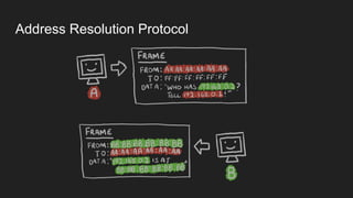
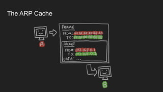
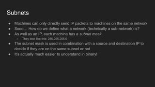
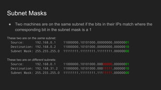
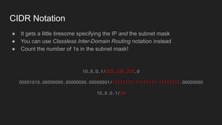
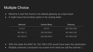
1. Networks use layers like TCP, IP, and Ethernet to transport data between devices using hardware addresses, IP addresses, ports, and protocols. Routers and switches help direct traffic between subnets.
2. HTTP is an application layer protocol that uses request and response messages to transfer resources like web pages. It relies on TCP for reliable transmission and uses IP addresses and ports to target specific servers and applications.
3. DNS converts human-readable domain names to IP addresses so that resources can be located on networks and the internet using names instead of raw addresses. It allows browsers to find web servers by name.