
Recommended
Recommended
More Related Content
What's hot
What's hot (20)
Similar to Mikro tik vpn configuration with site converted
Similar to Mikro tik vpn configuration with site converted (20)
Recently uploaded
Recently uploaded (20)
Mikro tik vpn configuration with site converted
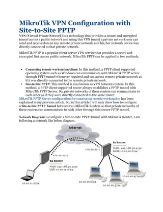
- 1. MikroTik VPN Configuration with Site-to-Site PPTP VPN (Virtual Private Network) is a technology that provides a secure and encrypted tunnel across a public network and using this VPN tunnel a private network user can send and receive data to any remote private network as if his/her network device was directly connected to that private network. MikroTik PPTP is a popular client-server VPN service that provides a secure and encrypted link across public network. MikroTik PPTP can be applied in two methods. ▪ Connecting remote workstation/client: In this method, a PPTP client supported operating system such as Windows can communicate with MikroTik PPTP server through PPTP tunnel whenever required and can access remote private network as if it was directly connected to the remote private network. ▪ Site-to-Site PPTP: This method is also known as VPN between routers. In this method, a PPTP client supported router always establishes a PPTP tunnel with MikroTik PPTP Server. So, private networks of these routers can communicate to each other as if they were directly connected to the same router. MikroTik PPTP Server configuration for connecting remote workstation has been explained in my previous article. So, in this article I will only show how to configure a Site-to-Site PPTP Tunnel between two MikroTik Routers so that private networks of these routers can communicate to each other through this secure PPTP tunnel. Network DiagramTo configure a Site-to-Site PPTP Tunnel with MikroTik Router, I am following a network like below diagram.
- 2. In this network, R1 Router is connected to internet through ether1 interface having IP address 192.168.30.2/30. In your real network this IP address should replace with public IP address. R1 Router’s ether2 interface is connected to local network having IP network 10.10.10.0/24. We will configure PPTP server in this router and after PPTP configuration the router will create a virtual interface (PPTP Tunnel) across public network whose IP address will be 172.22.22.1. On the other hand, R2 Router is a remote router and can access R1 Router’s WAN IP. R2 Router’s ether1 interface is connected to internet having IP address 192.168.40.2/30 and ether2 has a local IP network 10.10.11.0/24. We will configure PPTP client in this router and after configuration the router will have a virtual interface (PPTP Tunnel) across public network whose IP address will be 172.22.22.2. Site-to-Site PPTP Configuration in MikroTik Router Now we will start our Site-to-Site PPTP configuration in MikroTik Router according to above network diagram. Complete configuration can be divided into two parts. ▪ Part 1: R1 Router Configuration ▪ Part 2: R2 Router Configuration Part 1: R1 Router Configuration We will configure PPTP Server in R1 RouterOS. Complete RouterOS configuration can be divided into three steps. ▪ MikroTik Router basic configuration ▪ Enabling PPTP Server ▪ PPTP user configuration Step 1: MikroTik Router Basic Configuration In first step, we will assign WAN, LAN and DNS IP and perform NAT and Route configuration. The following steps will show how to do these topics in your RouterOS. ▪ Login to R1 RouterOS using winbox and go to IP > Addresses. In Address List window, click on PLUS SIGN (+). In New Address window, put WAN IP address (192.168.30.2/30) in Address input field and choose WAN interface (ether1) from Interface dropdown menu and click on Apply and OK button. Click on PLUS SIGN again and put LAN IP (10.10.10.1/24) in Address input field and choose LAN interface (ether2) from Interface dropdown menu and click on Apply and OK button. ▪ Go to IP > DNS and put DNS servers IP (8.8.8.8 or 8.8.4.4) in Servers input field and click on Apply and OK button. ▪ Go to IP > Firewall and click on NAT tab and then click on PLUS SIGN (+). Under General tab, choose srcnat from Chain dropdown menu and click on Action tab and then choose masquerade from Action dropdown menu. Click on Apply and OK button.
- 3. ▪ Go to IP > Routes and click on PLUS SIGN (+). In New Route window, click on Gateway input field and put WAN Gateway address (192.168.30.1) in Gateway input field and click on Apply and OK button. Basic RouterOS configuration has been completed. Now it is time to enable PPTP server in our MikroTik Router. Step 2: Enabling PPTP Server in MikroTik Router We will now enable PPTP Server in our MikroTik Router. The following steps will show how to enable PPTP Server in MikroTik RouterOS. ▪ Click on PPP menu item from winbox and then click on Interface tab. ▪ Click on PPTP Server button. PPTP Server window will appear. ▪ Check Enabled checkbox and also check pap and chap checkbox under Authentication panel. ▪ Click on Apply and OK button. PPTP Server is now running in our MikroTik Router. The next step is to configure PPTP user who will be authenticated to connect to PPTP Server for establishing a PPTP Tunnel. Step 3: PPTP User Configuration We will now create PPTP username and password that are required to connect to PPTP Server. We will also assign local and remote virtual interface IP. We will also add a static route in routing table to reach the client router’s private network. The following steps will show how to do these topics in your MikroTik Router. ▪ Click on PPP menu item from winbox and then click on Secrets tab. ▪ Click on PLUS SIGN (+). New PPP Secret window will appear. ▪ Put username (For example: sayeed) in Name input and password in Password input field. This username and password will be required when PPTP client will be configured. ▪ Put virtual interface IP for R1 Router end (172.22.22.1) in Local Address input field and for R2 Router end (172.22.22.2) in Remote Address input field. ▪ Put static routes to reach R2 Router’s local network in Routes input filed. This route will be added in R1 Router’s routing table when PPTP user will be connected from R2 Router. The route format is: dst-address gateway metric (example for this configuration: 10.10.11.0/ 24 172.22.22.2 1). Several routes may be specified separated with commas. ▪ Click on Apply and OK button. User configuration for PPTP Server has been completed. Whenever your created user will be connected from PPTP client router (R2 Router), the Remote Address IP will be assigned for its virtual interface and the routes will be created in R1 Router’s routing table so that R1 Router’s local network can reach remote router’s (R2 Router) local network. R1 Router configuration has been completed. Now R1 Router is ready to create PPTP Tunnel for its PPTP user. In the next part, we will configure our R2 Router so that it can connect to R1 Router through a PPTP Tunnel to reach R1 Router’s local network.
- 4. Part 2: R2 Router Configuration According to our network diagram, R2 Router is working as a PPTP client router. So, we will configure PPTP client in R2 Router. Complete RouterOS configuration can be divided into three steps. ▪ Basic RouterOS configuration ▪ PPTP client configuration ▪ Static route configuration Step 1: Basic RouterOS Configuration Basic RouterOS configuration includes assigning WAN, LAN and DNS IP as well as NAT and Route configuration. The following steps will guide you about basic RouterOS configuration. ▪ Login to R2 RouterOS using winbox and go to IP > Addresses. In Address List window, click on PLUS SIGN (+). In New Address window, put WAN IP address (192.168.40.2/30) in Address input field and choose WAN interface (ether1) from Interface dropdown menu and click on Apply and OK button. Click on PLUS SIGN again and put LAN IP (10.10.11.1/24) in Address input field and choose LAN interface (ether2) from Interface dropdown menu and click on Apply and OK button. ▪ Go to IP > DNS and put DNS servers IP (8.8.8.8 or 8.8.4.4) in Servers input field and click on Apply and OK button. ▪ Go to IP > Firewall and click on NAT tab and then click on PLUS SIGN (+). Under General tab, choose srcnat from Chain dropdown menu and click on Action tab and then choose masquerade from Action dropdown menu. Click on Apply and OK button. ▪ Go to IP > Routes and click on PLUS SIGN (+). In New Route window, click on Gateway input field and put WAN Gateway address (192.168.40.1) in Gateway input field and click on Apply and OK button. Basic RouterOS configuration in R2 Router has been completed. Now it is time to create PPTP client in our MikroTik Router. Step 2: PPTP Client Configuration After completing RouterOS basic configuration, we will now configure PPTP client in R2 Router. The following steps will show you how to create PPTP client in your MikroTik Router. ▪ Click on Interfaces menu item from winbox and then click on Interface tab. Click on PLUS SIGN (+) dropdown menu and then choose PPTP Client option. New Interface window will appear. ▪ Click on General tab and put PPTP interface name (pptp-server) in Name input field. ▪ Click on Dial Out tab and put R1 Router’s WAN IP (192.168.30.2) in Connect To input field. This IP must be reachable from R2 Router. ▪ Put username (sayeed) and password that you have created in R1 Router’s PPTP user configuration, in User and Password input field respectively. ▪ Click on Apply and OK button.
- 5. As soon as you provide the above information, a PPTP Tunnel will be created between R1 and R2 Router and provided local and remote IP address will be assigned in R1 and R2 Router’s virtual interface respectively. At this stage, R1 Router as well as its local network will be able to reach R2 Router and its local network but R2 Router and its local network will only be able to reach R1 Router but not its local network. To reach R1 Router’s local network, a static route must add in R2 Router’s routing table. Step 3: Static route configuration After configuring PPTP Client in R2 Router, R2 Router can only access R1 Router but not its local network. To solve this issue, a route is required in R2 Router’s routing table. The following steps will show how to add a route in R2 Router’s routing table statically. ▪ Go to IP > Routes and then click on PLUS SIGN (+). ▪ In New Route window, provide R1 Router’s local network (10.10.10.0/24) where you want to reach, in Dst. Address input field. ▪ Click on Gateway input field and then choose your PPTP client interface (pptp-server) that you have create in PPTP client configuration, from Gateway dropdown menu. ▪ Click on Apply and OK button. Now R2 Router and its local network will be able to access R1 Router’s local network. R1 Router and R2 Router Configuration for establishing a PPTP Tunnel between them has been completed. Now both router’s local networks are eligible to access each other. To check your configuration, do a ping request from any local network machine to other local network machine. If everything is OK, your ping request will be success. If you face any confusion to follow above steps properly, watch my below video about MikroTik PPTP Site-to-Site VPN configuration. I hope, it will reduce your any confusion. MikroTik VPN configuration with Site-to-Site PPTP Service has been explained in this article. I hope you will be able to configure your Site-to-Site VPN with MikroTik PPTP service if you follow the explanation carefully. However, if you face any confusion to do above steps properly, feel free to discuss in comment or contact with me from Contact page. I will try my best to stay with you.