Tacho Universal Update Repair Kit user manual
•
1 like•326 views

Tacho Universal Update Repair Kit user manual

Recommended
Recommended
More Related Content
Similar to Tacho Universal Update Repair Kit user manual
Similar to Tacho Universal Update Repair Kit user manual (20)
More from BuyobdtoolShop
More from BuyobdtoolShop (20)
Recently uploaded
Recently uploaded (20)
Tacho Universal Update Repair Kit user manual
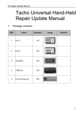
- 1. TU Repair Update Manual Tacho Universal Hand-Held Repair Update Manual 1 Package contains: NO. Name Quantity Image Remark 1 IC111 1PC 2 IC112 1PC 3 AT24C02 1PC 4 74HC541 1PC 5 IC removing tool 1PC 1
- 2. Trouble Solution Remark Screen display: Diga updaten Replace IC111 & IC112 Screen display: RESETE Replace IC111 & IC112 No display after powered on Replace IC111 & IC112 No vehicle list,screen display black strip Replace IC111 & IC112 Frequently Halting Replace IC111 & IC112 Screen display both the following: “update handheld”“???SYNC??? ” Replace AT24C02 & IC111 & IC112 The machine cannot read EEPROM Replace 74HC541 TU Repair Update Manual 2 Repair TACHO Universal Hand-Held Device 2.1 Trouble Shooting
- 3. TU Repair Update Manual 2.2 Solution 2.2.1Replace IC111 and IC112 as shown in the figure. 3
- 4. TU Repair Update Manual 2.2.2 Replace AT24C02 as shown in the figure. 4
- 5. TU Repair Update Manual 2.2.3 Replace 74HC541 5
- 6. TU Repair Update Manual 3 Update TACHO Universal Hand-Held Device 3.1 Remove the 8 screws, open the up cover, unplug the keyboard cable connector, and then remove the up cover as shown in the figure. 6
- 7. TU Repair Update Manual 3.2 Remove the CPU BOARD as shown in the figure. 7
- 8. TU Repair Update Manual 3.3 Remove IC111 and IC112 as shown in the figure. 8
- 9. TU Repair Update Manual 3.4 Remove AT24C02 as shown in the figure. AT24C02 AT24C02 9
- 10. TU Repair Update Manual 3.5 Remove PIC12F629 as shown in the figure. 11
- 11. TU Repair Update Manual 3.6 Install IC111 and IC112. Make sure the install direction is correct. See the figure. 12
- 12. TU Repair Update Manual 3.7 Install AT24C02. Make sure the install direction is correct. See the figure. 13
- 13. TU Repair Update ManualTU Repair Update ManualTU Repair Update Manual 3.8 On your board, if there are not components in position 1 and 2, please remove component in position3. and then fix PIC12F629 onto the position on 1. fix OSC on the proper position in 2. 16
- 14. TU Repair Update Manual 3.9 Install CPU BOARD. Make sure install it in correct direction. See the figure. 17
- 15. TU Repair Update Manual 3.13 Install the up cover and then the 8 screws. See the figure. 18
- 16. TU Repair Update Manual 4 Update methods: Step 1. Remove the CPU BOARD from TACHOPRO i.e. the principal machine. See picture 1. 19
- 17. TU Repair Update Manual Picture 1 Step 2. Find the location of IC111& IC112 and replace the previous IC on CPU BOARD with the IC111&IC112 of Update Kit. Make sure the IC is properly located with correct direction. See picture 2 Picture 2 20
- 18. TU Repair Update Manual Step 3. Find AT24C02 on CPU BOARD. Remove the previous IC by using electric iron and then place AT24C02 on the corresponding location to guarantee the direction of IC. See picture 3A, 3B Picture 3A picture 3B Note: pay attention to CPU BOARD in picture 3A. First of all, the IC socket should be taken out from AT24C02 and then weld AT20C02 to the specified position in picture 3B. 21