1. 3/8, Reducing Valves
For "P" Line: MRP-03- -30/3090
For "A" Line: MRA-03- -30/3090 MODULAR
For "B" Line: MRB-03- -30/3090 VALVES
Specifications / Others
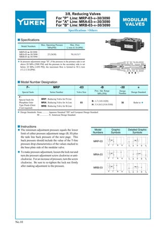
Specifications
Max. Operating Pressure Max. Flow
Model Numbers
MPa(PSI) L/min (U.S.GPM)
MRP-03- -30/3090
MRA-03- -30/3090 25 (3630) 70 (18.5)
MRB-03- -30/3090
In pressure adjustment range "H", if the pressure in the primary side is set
above 20 MPa (2900 PSI) and the pressure in the secondary side is set
below 10 MPa (1450 PSI), the maximum flow is limited to 50 L/min
(13.2 U.S.GPM).
Model Number Designation
F- MRP -03 -B -30
Pres. Adj. Range Design
Special Seals Series Number Valve Size Design Standard
MPa (PSI) Number
F:
Special Seals for MRP : Reducing Valve for P-Line
B: 1-7 (145-1020)
Phosphate Ester MRA : Reducing Valve for A-Line 03 30 Refer to
Type Fluids (Omit H: 3.5-24.5 (510-3550)
MRB : Reducing Valve for B-Line
if not required)
Design Standards: None ........... Japanese Standard "JIS" and European Design Standard
90 ............... N. American Design Standard
Instructions
The minimum adjustment pressure equals the lower Model Graphic Detailed Graphic
limit of either pressure adjustment range (B, H) plus Numbers Symbols Symbols
the tank line back pressure of the next page. This
back pressure should include the value of the T-line MRP-03
pressure drop characteristics of the values stacked to P T B A TA A P B TB
the base plate side of the modular valve.
To make pressure adjustment, loosen the lock nut and
turn the pressure adjustment screw clockwise or anti- MRA-03
clockwise. For an increase of pressure, turn the screw P T B A TA A P B TB
clockwise. Be sure to re-tighten the lock nut firmly
after making adjustment to the pressure.
MRB-03
P T B A TA A P B TB
No.10
2. 3/8, Reducing Valves
For "P","A" and "B" Lines MODULAR
Typical Performance Characteristics
VALVES
Hydraulic Fluid: Viscosity 35 mm2/s (164 SSU), Specific Gravity 0.850
Pressure Drop
PSI MPa
0.3 A&B-Line
40
P
30 0.2
Pressure Drop
20
0.1
10 T-Line
0
0
0 10 20 30 40 50 60 70 L /min
0 4 8 12 16 18 U.S.GPM
Flow Rate
cu.in./min
50
cm3/min
800
Pilot Flow
F
40
600
Pilot Flow
30
400
20
200
10
0
0
0 5 10 15 20 25 MPa
0 1000 2000 3000 3500 PSI
Differential Pressure
(Primary pressure - Secondary pressure)
Pres. Drop at Spool Fully Open (P-Line)
PSI MPa
70 0.5
60 0.4
P
50
0.3
Pressure Drop
40
30 0.2
20
0.1
10
0
0
0 10 20 30 40 50 60 70 L /min
0 4 8 12 16 18 U.S.GPM
Flow Rate
No.11
3. 3/8, Reducing Valves
For "P","A" and "B" Lines MODULAR
Installation Drawing / Spare Parts List
VALVES
MRP-03- -30/3090
DIMENSIONS IN
MRB-03- -30/3090 MILLIMETRES (INCHES)
7(.28) Dia. Through
Lock Nut 92(3.62)
4 Places
14(.55) Hex. 19 54
(.47)
12
(.75) (2.13)
Thread Size
Model Numbers
14(.55)
P
A B
"C" Thd.
(1.81)
(2.76)
MB -01- -30 Rc 1/4 = 1/4 BSP.Tr
46
70
TA TB
MB -01- -3090 1/4 NPT
Fully Extended
(.07)
1.8
Pressure Adj. Screw 132(5.20)
14(.55) Hex.
Fully Extended 233.5(9.19)
INC.
Pressure Gauge Connection
"C" Thd.
(2.17)
55
(1.08)
Approx. Mass............ 3.8 kg (8.4 lbs.)
27.5
MRA-03- -30/3090
Fully Extended 233.5(9.20)
47.5
Pressure Gauge Connection (1.87)
"C" Thd.
P
A B
TA TB
Approx. Mass............ 3.8 kg (8.4 lbs.)
For other dimensions, refer to "MRP-03" drawing above.
Spare Parts List
MRP-03- -30/3090 MRB-03- -30/3090
11 10 3 5 15 18 16 3 4 1 2 19 9 17 13
6 7 14
List of Seals
MRA-03- -30/3090
Item Name of Parts Part Numbers Qty. Remarks
14 O-Ring SO-NB-A014 5
15 O-Ring SO-NA-P6 1
Included in Seal Kit
16 O-Ring SO-NB-P16 1 Kit No.:
KS-MRP-03-30
17 O-Ring SO-NB-P18 1
18 O-Ring SO-NB-P26 1
CAUTION
When making replacement of seals, please do it carefully after reading
through the relevant instructions in the Operator's Manual.
No.12