The document describes the development of a mechanical platform for a binocular robotic vision system inspired by human vision. The platform uses mechanically coupled pan, tilt, and vergence movements to focus two eye components on points of interest, reducing the need for complex image processing. Testing validated the theoretical design analysis and achieved coupling of the three degrees of freedom. Recommendations include using more precise parts and actuation to increase precision and accuracy of eye movements.
1. Mechanical Platform for a Binocular Robotic Vision System
Objective
Functional Requirements
Mechanical Design
To develop, analyze, construct, and test a mechanical platform for a
binocular robotic vision system, inspired by the human vision system, that
is capable of focusing two eye components on an individual point of
interest in a scene through mechanically coupled pan, coupled tilt, and
coupled vergence movements of the eyes.
• Mechanically-coupled eye movements to reduce synchronization error
and thereby decrease the need for complex image processing
• Based on potential application of mechanism in social robotics:
o Eye velocity and acceleration specifications based on human
saccadic eye movements
o Range of motion and resolution selected to allow realistic use in
human-robot interaction
The results of the mechanical prototype tests validated the theoretical
platform analysis. Coupling each of the three degrees of freedom in the
pair of eyes was achieved. The following are recommended for
mechanism improvement:
• Higher precision standard parts to reduce play, backlash, and friction in
links and joints
• More precise and compact actuation to increase precision and
accuracy of movement and reduce the size of the platform for practical
mounting
• Cameras to sense focal point position error for closed loop control
• SPI reading to obtain absolute encoder values for platform calibration
System Architecture
Stepper motors
Linear slider
convergence
mechanism
Control bar
Tilt
mechanism
Mount for
laser-pointer
eye (left)
Universal joint
x
y
z
Slider linkages translate
linear movements of
control bar into pan and
convergence of eyes
Linear slider pan
mechanism
ΔCz
ΔCx
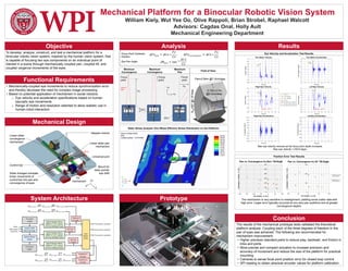
Analysis
Focus
point
Focus
point
Focus
point
Minimum
Convergence
Maximum
Convergence
Maximum
Pan
+x
+z
Fz
FxLines of
sight
ΔCz
ΔCx
Prototype
Results
Conclusion
Pan=2.84m @1.5cm/step
0.75m-2.7m
@2.0cm/step
θTilt=90º@1.8º/step
y
-x
z
Field of View
eyes
Static Stress Analysis (Von Mises Effective Stress Distribution on the Platform)
Eye Velocity and Acceleration Test Results
Position Error Test Results
The mechanism is very sensitive to misalignment, yielding some outlier data with
high error. Larger error typically occurred at non-zero pan positions and at greater
convergence depths.
Max eye velocity reduces as the focus point depth increases
Max eye velocity = 230.8 deg/s
Fx = 0
Fx =104 cm
Fx = -104 cm
Fx = 0
Fz from 75 to 178 cm
Fz from 178 to 273 cm
Focus Point Cartesian
Position:
Eye Pan Angle: