1. 1 | P a g e
PACM Reactor 7 Seal Repair July 15 - 17, 2013
Jordan Watkins & Wichita Maintenance Engineering Team
July 15
th
through July 17
th
, 2013, I arrived at the IPEG facility in Calvert City, KY to witness the refurbishment of the Reactor 7 agitator
seal, which was removed after seven months of operation. This report documents the “as-found” and “as-left” condition of the seal,
installation observations, associated cost, future recommendations, and contact information.
“As-Found” Seal Condition
This section serves to describe the condition of the seal before and during the teardown of seal assembly (SN 7-8-B). Prior
refurbishments have uncovered issues that are common failure points in such an assembly and will be discussed further in this
report. All findings in this report will be followed by recommendations for repair in the action items list in appendix C.
Initial Pressure Test
Before commencing teardown a pressure test is done to provide visual evidence of what was found in the field, as in this case, oil
leaking in to the reactor. To pressure test the seal, oil is hand-pumped into the seal assembly until the pressure gauge reaches
1200psi, and is held for 30 minutes. A reasonable amount of pressure loss in 30 minutes is 200 psi; any higher and the seal is in need
of rebuilding. For the initial test we pressured the assembly up to 900 psi. Within 1 minute oil started draining from the bottom of
the seal gland indicating that we had a major inboard seal failure. We determined that a seal teardown was necessary to determine
the cause.
Primary Rings
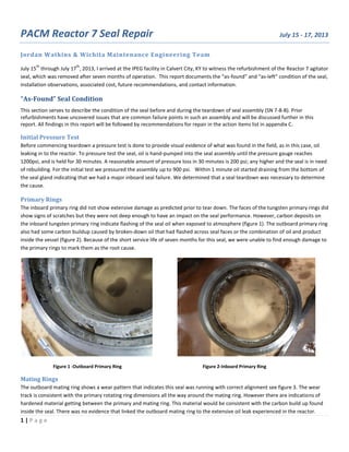
The inboard primary ring did not show extensive damage as predicted prior to tear down. The faces of the tungsten primary rings did
show signs of scratches but they were not deep enough to have an impact on the seal performance. However, carbon deposits on
the inboard tungsten primary ring indicate flashing of the seal oil when exposed to atmosphere (figure 1). The outboard primary ring
also had some carbon buildup caused by broken-down oil that had flashed across seal faces or the combination of oil and product
inside the vessel (figure 2). Because of the short service life of seven months for this seal, we were unable to find enough damage to
the primary rings to mark them as the root cause.
Figure 1 -Outboard Primary Ring Figure 2-Inboard Primary Ring
Mating Rings
The outboard mating ring shows a wear pattern that indicates this seal was running with correct alignment see figure 3. The wear
track is consistent with the primary rotating ring dimensions all the way around the mating ring. However there are indications of
hardened material getting between the primary and mating ring. This material would be consistent with the carbon build up found
inside the seal. There was no evidence that linked the outboard mating ring to the extensive oil leak experienced in the reactor.
2. 2 | P a g e
Figure 3 - Outboard Mating Ring
During the investigation of the inboard mating ring, a large fracture was found. The size of the fracture was about a half inch long by
a quarter inch wide as seen in figure 4 & 5 below. The location of the fracture is relative to the tabs on the retainer ring. The retainer
ring is used to prevent the mating ring from moving out of place during a pressure fluctuation. There are four tabs equally sectioned
on the mating ring to keep it in place as shown in figure 6. There is a 0.005” clearance between the retaining ring tabs and the
mating ring governed by John Crane specifications. Also noted on the mating ring was four equally placed heavy scratch marks in-
between the four tabs as shown in figure 7. These marks indicate to us that during the running of this seal we had high pressure on
the process side flexing the mating ring in-between these tabs which coincides with the fracture at one of the retainer ring tabs. This
fracture would explain why we had a sudden loss of 75 gallons of oil to the reactor. Investigation into the process pressure trend
may give us an indication of what might have happened around the time of the failure. In appendix C, item 3 will be the solution to
prevent this type of pressure fluctuation from occurring.
Note: The team is looking at options to monitor the lubrication system pressure. This will include a pressure differential control
system to keep a 50 psig pressure differential between the reactor pressure and the barrier fluid system.
3. 3 | P a g e
Figure 4 - Fracture Showing Location of Tab
Figure 5 - Inboard Mating Ring Side View of Fracture
4. 4 | P a g e
Figure 6 – Inboard Mating Ring Retainer Ring
Figure 7 - Inboard Mating Ring High Scratch Marks
5. 5 | P a g e
Shaft
The shaft shows normal signs of wear. A 10-ton press was needed to pull the bearing from the shaft because of the tight bearing
clearance. Shaft run out was within .002” of design. The oil markings shown in Figure 7 show that the o-rings sealed properly against
the shaft during its seven month service period.
Figure 8 -Stub Shaft after Disassembly
O-rings
All o-rings found in the seal were confirmed to be of Kalrez 1050LF grade. All eight o-rings had no sign of rips, tears, or fraying. O-
rings were measured for proper crush to verify proper clearance between the cavities in which the o-rings sit and the compression
plate. Values measured include the o-ring diameter, cavity depth, and o-ring crush diameter. Acceptable tolerance is 5-30% for static
seal designs. All seal o-rings measured are within tolerance as shown in Table 1 in Appendix A.
“As-Left” Seal Condition
John Crane provided us with a refurbishment kit for the seal which included inboard and outboard mating rings, inboard and
outboard primary rings, springs, and new o-rings. Since mating rings are lapped to a very fine finish a light band test was done on the
mating rings to verify that the surface was within specification. The light band test proved that the finish on the faces of the new
mating rings were the correct pattern. All Kalrez o-rings were measured and compared to the drawing for accurate part description
and greased. New top (Large Bearring) and lower (Small Bearing) bearings were purchased, greased with Ulti-Plex synthetic grease
and installed into the refurbished seal. The shaft was cleaned, polished, and verified to be within tolerance. The outside housing was
repainted for aesthetic purposes.
Pressure Test
The seal requires a final pressure test to check for leaks after being fully reassembled. Again, oil was hand-pumped into the seal
assembly until the pressure gauge read 1200 psi; after the 2 hours the seal had only lost 60 psi. The test was successful and the seal
was ready to be put in the box for shipment.
6. 6 | P a g e
Figure 9 - Final Pressure Test
Installation Observations
An observation was done on the installation of reactor 7 seal to evaluate any concerns with potential damage to the seal during this
process. This section will be used to describe all findings observed during the installation to include installation procedure and gear
box changes.
Installation Procedure
During the installation the seal is first hoisted to the top railing with a chain hoist. Once this hoist reaches the top level it is slid over,
on the hoist, to the side of the reactor. One thing to note was that the chain fall is directly over the centerline of the gear box with
no allowance for easy left or right movement. The seal was physically moved over by personnel (Figure 10) and held in place until it
was slowly dropped down on glide plates. These glide plates are T shaped steel plates which are used to laterally position the seal
above the gear box shaft shown in figure 11. Moving the seal on these plates is physically difficult and ergonomically deficient.
Moving the heavy seal on steel plates is very difficult do to the nature of friction and the fact that the dimensions of the “T” bars do
not fit the seal diameter. The seal has to be rocked into place increasing the chance of damaging the seal internals. To assess this
situation the team will be investigating a better way to position and install this seal.
Figure 10 - Installation using Chain Hoist Figure 11 - Installation Using Steel “T” Frame members
7. 7 | P a g e
Gear Box Changes
Once the seal had been positioned below the gear box shaft the shaft was lowered to bolt the seal housing. When the seal housing
has been bolted to the gear box shaft a run out is done to check the alignment of the seal as shown in figure 12. It was determined
that the seal was off by 0.010” and the seal could not be fully aligned without moving the gear box slightly. The gear box bolts were
loosened from the mounting frame and incrementally moved until the alignment of the seal housing to the gear box was within
specifications of ±0.002”. The final TIR of the seal assembly to the gear box shaft was 0.001”.
Figure 12 - TIR of Seal Housing to Agitator Shaft
Before we could start up the reactor it was noticed that the agitator shaft was rotating in the wrong direction. As specified by
Philadelphia Mixing Solutions, the gear box shaft must rotate in the clockwise direction when looking down at the shaft. During
previous normal operation the shaft was witnessed to be rotating in the counter-clockwise direction. I was able to contact Ed
Gamber, director of Engineering at Philadelphia Mixing Solutions, and confirm the correct agitator rotation as clockwise. Ed’s
concern was that if the agitator had been running in the counter-clockwise direction for an extended period of time, damage could
be seen in the bearings upon teardown. Investigation of the bearings during teardown did show signs that the small bearing had
been taking more of the load in comparison with the larger steady bearing shown in figures 13 & 14. Do to the findings and no
evidence as to why the agitator was rotating in the counter-clockwise direction the decision was made to switch the leads on the
agitator motor to rotate in the clockwise direction.
Figure 12 - Small Bearing Figure 14 - Large Bearing
Wear tracks on
small bearing
Little to no
wear tracks on
large bearing
8. 8 | P a g e
Associated Costs
Costs associated with this refurbishment pertain to the shipping cost (expedited), replacement seal parts from John
Crane, and IPEG repair services. Appendix B, Table 2 details all costs associated with this seal rebuild.
Contact Information
Jeff Richard
Sales Engineer
Industrial Process Equipment Group (IPEG)
270-395-5711
jrichard@ipegstl.com
Doug McCoy
Shop Superintendent
Industrial Process Equipment Group (IPEG)
270-395-5711
dmccoy@ipegstl.com
Scott Symons
GO GSS Mechanical Engineering
Air Products Corporate HQ
610-481-1625
SYMONSSR@airproducts.com
Jordan Watkins
Maintenance Reliability Engineer
Air Products Wichita PMD Plant
316-529-9643
watkinj1@airproducts.com
9. 9 | P a g e
APPENDIX A
O-ring Crush Data
Table 1: O-ring Crush after Installation (7 Month Service Life)
O-ring # Function Nom O-ring Dia. (In) Crush Dia. (In) Crush % Acceptable
2 IB Mating Ring 0.139 0.124 10.8% Yes
4 IB Primary Ring 0.139 0.120 13.7% Yes
13 OB Mating Ring 0.139 0.126 9.4% Yes
15 OB Primary Ring 0.139 0.122 12.2% Yes
24 upper Seal Sleeve 0.139 0.119 14.4% Yes
24 lower Seal Sleeve 0.139 0.118 15.1% Yes
26 Gland 0.139 0.121 12.9% Yes
29 Oil Dam 0.139 0.117 15.8% Yes
*Acceptable qualification based on static seal designs: Crush value of 5-30% of nominal o-ring diameter.
10. 10 | P a g e
APPENDIX B
Associated Costs
Table 2: Associated Costs
Freight Costs
$4,583.93
Replacement Parts
$35,349.00
Shop Labor
$3,809.08
Internal Material
$1,069.56
Total Cost: $44,811.57
12. 12 | P a g e
Table 3: RX 7 Seal Repair Action Items List
Task
#
Task Description Task Leader Due Date
1 Evaluate the need for a RX 7 Gear Box
rebuild. Note we have a spare Gear Box
in House. RX 8 Gear Box was done in
2008. Would be a shutdown item.
Jordan Watkins 9/15/2013
2 Evaluate need for RX 7 Gear Box
Vibration Monitoring Probe. Work with
Balance Plus on new technology
Jordan Watkins,
Scott Symons,
Balance Plus
10/30/2013
3 Possible Project to install a pressure
differential control system to keep
barrier fluid pressure above reactor
pressure by 50 psig preventing the
process pressure from slamming the
inboard mating ring into the retaining
ring tabs.
Jordan Watkins,
Alan Abel &
Scott Symons
8/29/2013
4 Incorporate an alarm system to warn of
loss of pressure differential on
lubrication system also look at
monitoring lubrication pressure.
Jordan Watkins,
Alan Abel &
Scott Symons
8/29/2013
5 Check lubrication lines for plugs Todd Allen 8/29/2013
6 Send out sample of charred substance
found in seal to determine material.
Jordan Watkins 8/29/2013
7 Design a better way to install the seal
that would limit the amount of rocking
needed. Cut steel "T" bars to correct
dimensions so seal can slide on bars
without interruption.
Todd Allen,
Jordan Watkins
10/30/2013
8 PTFE substance found around seal
retainer ring, check/replace filter &
stop the use of Teflon tape.
Todd Allen
7/29/2013
Complete
9 Swapped Motor leads for clockwise
rotation
Russ Partain
7/1/2013
Complete
10 Shaft hook used to move gear box shaft
up needs to be able to rotate. Look at
new hook design.
Jordan Watkins
7/20/2013
Complete
11 Gear Box bearing needs a spacer to
keep it steady. Look into technology
that is used for this or what other
plants are doing.
Todd Allen,
Jordan Watkins
7/2/13
Complete
12 Evaluate Process conditions and the
difference between RX 8. Note
differences and commonalities.
Jordan Watkins 8/15/2013