IRJET- Design and Theory of Powertrain of Formula Student {FSAE} Car
Baja Falcons Tuning and Instrumentation Team IGEN430 Poster - VR (1)
1. Baja Falcons Tuning and Instrumentation Team
Cody R, Dave D, Sean H, Tara K-S, Vaughn R
Integrated Engineering - University of British Columbia
Client: UBC Baja SAE
• UBC Baja SAE is a student engineering team that designs and builds off-
road racing vehicles for international competition against other universities
• Power limited, stiff competition and rugged operating conditions
• Efficiency, reliability, driver safety, informed tuning and weight reduction
are essential
Onboard Data Acquisition System
Objective – Deliver an onboard data-acquisition system and wiring harness
that is reliable, modular and easy to install/uninstall on vehicle.
In this initial configuration, six sensors record information about the vehicle.
Engine and Wheel RPM – Hall effect sensors located on the engine and
final drive collect rpm data. This data allows drivetrain reduction ratio to be
calculated, CVT behaviour to be analysed and vehicle speed to be tracked.
Project Objective
Provide UBC Baja SAE with tools to improve vehicle performance through:
1. Continuously variable transmission (CVT) tuning
2. Informed design, tuning and vehicle operation based on real-world data
Continuously Variable Transmission (CVT)
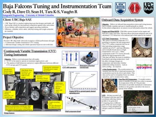
Tuning Instrument
Objective - Deliver a test instrument that will enable:
i. A CVT to be tuned to operate at maximum engine power, and
ii. The analysis of shift behaviour and power output differences between different
CVT set-ups and CVT models
x: 0.58
y: 0.32
z: 1.02
rpm1: 2234
rpm2: 196
oilTemp: 106C
cvtTemp: 68C
Lat/Lon: 45.6322, -122.2550
Tachometer:
Tune CVT to
operate at
discrete
engine rpm
points
Flywheel & Tachometer:
Quantify power output
from CVT
Flywheel
Enclosure: Protect
user and bystanders
Disk Brake: Stop
flywheel in < 3s,
inherently safe –
brake is on by
default
Arduino &
Matlab:
Read, plot, and
visualize data
Throttle lever:
Manual engine
throttle control
Engine mounting
plate:
Provide adjustment
for different CVTs
Rigid test rig structure with flat top: Multi-
use structure also serves as a welding table
and chassis torsional rigidity testing platform
Design features
CVT shift operation
Engine RPM vs. ground speed: desired
operating curve
Illustration of flywheel
(inertial load)
Shaft component detail
CVT Belt Temperature – An Infrared
(IR) sensor is mounted within the CVT
guarding to measure the belt temperature.
The CVT’s rubber composite belt has an
ideal operating temperature range
(ambient up to 82°C) and loses efficiency,
and eventually breaks-down, in high
temperatures (over 105°C). Other
components in the CVT can be adversely
affected by high temperatures also.
This data will allow the team to establish a
benchmark operating temperature, track
the effect of design changes on
temperature and determine whether
additional cooling measures – such as
active cooling – are required.
3-Axis Accelerometer – The accelerometers are
mounted near the driver’s head and measures the
accelerations seen by the driver and vehicle. This
data can be used to extrapolate forces on vehicle
and driver, and to monitor driver safety.
GPS – All data recorded will
be stamped with time and GPS
coordinates allowing velocity
profiles to be generated.
Comparing data at different
parts of the race such as tight
corners or long straightaways
will give context to recorded
data.
Gear Box Oil Temperature – A variable resistive
sensor is installed in the gear box order to measure
the temperature of the oil. This provides
information on possible mechanical or lubrication
problems in the gearbox and allows the team to
operate more reliably.