Beginners Guide to TikTok for Search - Rachel Pearson - We are Tilt __ Bright...
The right ball screw jack
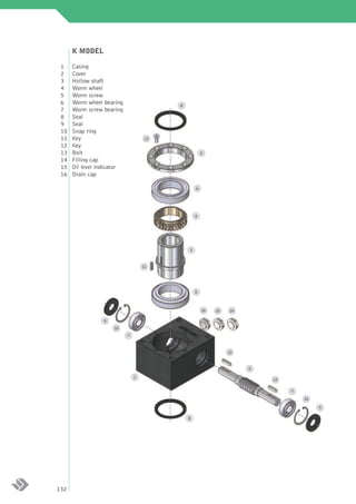
1. K MODEL
1 Casing
2 Cover
3 Hollow shaft
4 Worm wheel
5 Worm screw
6 Worm wheel bearing 8
7 Worm screw bearing
8 Seal
9 Seal
10 Snap ring
11 Key 13
12 Key
13 Bolt 2
14 Filling cap
15 Oil level indicator
16 Drain cap
6
4
3
11
6
16 15 14
9
10
7
12
5
1
12
7
10
9
8
132
2. MK MODEL
Casing 1
Cover 2
Hollow shaft 3
Worm wheel 4
Motor worm screw 5.1
Worm wheel bearing 6
Worm screw bearing 7
8 Motor worm screw bearing 7.1
Seal 8
Seal 9
Seal for motoring 9.1
13
Snap ring 10
Snap ring for motoring 10.1
2
Key 11
Key 12
Bolt 13
Filling cap 14
Oil level indicator 15
6 Drain cap 16
Motor flange 17
Bolt 18
4
3
11
exploded views and spare parts
6
16 15 14
9
10
7
17
1 12
18
5.1
7.1
8
10.1
9.1
133
3. DIMENSIONING OF THE BALL SCREW JACK
For a correct dimensioning of the ball screw jack it is necessary to observe the following steps:
Definition of the application data (A)
Change the size
Calculation of the unit load (B)
or mounting scheme
negative
Verification at static load (C)
Positive
Calculation of the equivalent load (D)
Calculation of inertia power (E)
negative
Verification at the equivalent power (F)
Positive
negative
Verification at thermal power (G)
Positive
negative
Verification at the torque (H)
Positive
negative
Verification at the radial loads (I)
Positive
negative Change ball screw type
Verification of the ball spindle (J)
or geometry
Positive
end
134
4. A – THE APPLICATION DATA
For a right dimensioning of the screw jacks it is necessary to identify the application data:
LOAD [daN] = the load is identified with the force applied to the translating device of a screw jack. Normally
the dimensioning is calculated considering the maximum applicable load (worst case). It is important to
consider the load as a vector, which is defined by a modulus, a direction and a sense, the modulus quantifies
the force, the direction orients spatially and gives indications on the eccentricity or on possible lateral loads,
the sense identifies the traction or compression load.
TRANSLATION SPEED [mm/min] = the translation speed is the load handling speed. From this speed it is
possible to calculate the rotation speed of the rotating devices and the necessary power for the movement.
Wear phenomena and the life of the screw jack proportionally depend on the value of the translation speed.
STROKE [mm] = it is the linear measure used to handle a load. It does not always coincide with the total
length of the ball spindle.
AMBIENT VARIABLES = these values identify the environment and the operating conditions of the screw
jack. Among them: temperature, oxidizing and corrosive factors, working and non-working periods, vibrations,
maintenance and cleaning, insertion frequency, foreseen operating life etc.
MOUNTING SCHEMES = There are several ways of handling a load by means of screw jacks. The schemes
on pages 162-163 will show you some examples. Choosing a mounting scheme will condition the choice of
the size and the power which is necessary for the application.
B – THE UNIT LOAD
According to the n number of screw jacks contained in the mounting scheme it is possible to calculate each screw
jack’s load dividing the total load by n In case the load is not fairly distributed in all screw jacks, it is recommended
to consider the transmission having the heaviest load, by virtue of a dimensioning based on the worst case.
C – THE STATIC LOAD
As very first step for the verification of the ball screw jack body, it’s important verify the internal components
resistance. The following table gives, entering with the static load C and the geometry of the ball screw (diameter
and pitch), the admissible jack sizes. If a certain size is in a colored area, it means that such application can
generate internal strength whose values are next to the bearings or gears limit ones; it’s suggested to choose the
higher size.
If a jack body can sustain a determined static load C, it’s not automatically true that the ball spindle can sustain
that load. It’s necessary a ball screw verification following the builder’s rules (point J).
If a jack body can sustain a determined static load C, it’s not automatically true that the body can sustain that
load in dynamic conditions. It’s necessary to verify the equivalent power (point F).
Static load C [daN]
Ball screw 1500 2000 3000 5000 8000 10000 15000 20000 30000
(diameter x pitch)
Ø 16x5 59 88 - - - - - - - -
Ø 16x16 59 88 - - - - - - - -
Ø 20x5 59 88 59 88 - - - - - - -
Ø 20x20 59 88 59 88 - - - - - - -
Ø 25x5 59 88 59 88 59 88 - - - - - -
Ø 25x10 59 88 59 88 59 88 - - - - - -
Ø 25x20 59 88 59 88 59 88 - - - - - -
Ø 25x25 59 88 59 88 59 88 - - - - - -
Ø 32x5 59 88 59 88 59 88 59 88 - - - - -
Ø 32x10 59 88 59 88 59 88 59 88 - - - - -
Ø 32x20 59* 88 59* 88 59* 88 59* 88 - - - - -
Ø 32x32 59* 88 59* 88 59* 88 59* 88 - - - - -
Ø 40x5 - 59* 88 117 59* 88 117 59* 88 117 59* 88 117 59* 88 117 - - -
Ø 40x10 - 59* 88 117 59* 88 117 59* 88 117 59* 88 117 59* 88 117 - - -
Ø 40x20 - 59* 88 117 59* 88 117 59* 88 117 59* 88 117 59* 88 117 - - -
dimensioning
Ø 40x40 - 59* 88 117 59* 88 117 59* 88 117 88 117 88 117 - - -
Ø 50x5 - - 88 117 88 117 88 117 88 117 88 117 - -
Ø 50x10 - - 88 117 88 117 88 117 88 117 88 117 - -
Ø 50x16 - - 88 117 88 117 88 117 88 117 88 117 - -
Ø 50x20 - - 88* 117 88* 117 88* 117 88* 117 88* 117 - -
Ø 50x40 - - 88* 117 88* 117 88* 117 88* 117 88* 117 - -
Ø 50x50 - - 88* 117 88* 117 88* 117 88* 117 117 - -
Ø 63x10 - - - 88* 117 88* 117 88* 117 88* 117 88* 117 -
Ø 63x20 - - - 88* 117 88* 117 88* 117 88* 117 88* 117 -
Ø 63x40 - - - 88* 117 88* 117 88* 117 88* 117 117 -
Ø 80x10 - - - - 88* 117 88* 117 88* 117 88* 117 88* 117
Ø 80x20 - - - - 88* 117* 88* 117* 88* 117* 88* 117 88* 117*
* This spindle size can be assembled only on KR models. For KT application please contact our technical office
135
5. D – THE EQUIVALENT LOAD
All the values listed in the catalogue refer to a standard use conditions, i.e. under a temperature of 20° and a
regular daily operation of 8 hours without shocks. Using the screw jack under the above conditions you can
foresee a 10.000 hours lifetime (with a working percentage of 70%).
For different application conditions the equivalent load should be calculated: it refers to the load which would
be applied in standard conditions in order to have the same thermal exchange and wear effects, which the real
load achieves in the real conditions of use.
It is therefore advisable to calculate the equivalent load according to the following formula:
Ce = C•fg•fa•fd
The usage factor fg
By means of the following diagram the fu use factor can be calculated according to the daily working hours.
1,3
1,2
1,1
1
0,9
Usage factor fg
0,8
0,7
0,6
0 4 8 12 16 20 24
Daily working hours [h]
The ambient factor fa
By means of the following table it is possible to calculate the fa factor according to the operation conditions.
Type of load Daily working hours [h] 3 8 24
Light shocks, few insertions, regular movements 0,8 1 1,2
Medium shocks, frequent insertions, regular movements 1 1,2 1,5
High shocks, many insertions, irregular movements 1,2 1,8 2,4
The duration factor fd
The duration factor fd is calculated as a function of the theoretical foreseen lifetime (expressed in hours)
2,2
2
1,8
1,6
1,4
Duration factor fd
1,2
1
0,8
0,6
0,4
1000 10000 100000
foreseen lifetime [h]
136
6. E – THE INERTIA POWER
In case of high accelerations and decelerations it is necessary to calculate the inertia power P . It is the power
J
necessary to support the inertia forces and torques opposed by the system in presence of a speed change.
First the designer should calculate the system inertia downstream of the screw jack Jv by reducing them first
to the hollow shaft (on which is mounted the ball screw), and then to the worm screw (input shaft). The Jv
inertias are the system inertias (typically masses) as well as the ball spindle and lead nut inertias.
After that, it is necessary to add the inertia of the screw jack Jk, obtainable from the tables below, in order to
have the value of the total inertia J reduced to worm screw. We remind that inertia is expressed by [kg•m2].
Size 59 88 117
Jk screw jack inertia [kg•m2] 0,0040608 0,0254982 0,0798326
Given ωv the input rotation speed and αv the input angular speed the inertia torque applied is equal to J•ωv
and the respective inertia power PJ is equal to J•ωv•αv. If the time changes of the input speed ωv can be
referred to one of the linear of sinusoidal schemes below, where A is the maximum speed in [rpm] and B is
the cycle frequency in [Hz], it is possible to simplify the inertia power calculation in [kW], by identifying A
and B parameters and by calculating:
2•J•A2•B
PJ =
91188
Rotation speed [rpm]
Rotation speed [rpm]
time [s] time [s]
Rotation speed [rpm]
Rotation speed [rpm]
time [s] time [s]
A
dimensioning
Rotation speed [rpm]
0 1/(2B) time [s] 1/B
137
7. F – THE EQUIVALENT POWER
Once the equivalent load Ce is calculated, it’s possible to verify the equivalent power (out the jack-ball spindle
system) as Pe=Ce•v, where v is the load translation speed. Dividing the equivalent power on the ball screw efficiency
ηa (this is a ball screw builder’s data) and on the jack efficiency ηk and adding this value to the inertia power PJ,
the equivalent input power Pei is obtained.
Ce•v
Pei = + PJ
ηa•ηk
The very first selection of a ball screw jack body is by the power tables (see pag. 140), choosing the size that, at a
determined rotating input or output speed, presents an input power Pi higher than Pei. If this value is a colored area, it
means that the life of the components or the thermal exchange is not sufficient; It’s suggested to change size, to low design
requirements or ask to our technical office more a more precise calculation.
The equivalent power is not the power requested by the single screw jack, unless the three correction factors fg, fd and
fa have a unit value.
Please note that, once translation speed v is fixed, the ball screw choice must not cause an input rotation speed higher
than 3000 rpm. The following table reports the maximum translation speed in function of the ball screw pitch.
Ball screw pitch [mm] maximun translation speed at 3000 rpm [mm/min]
5 3000
10 6000
16 9600
20 12000
25 15000
32 19200
40 24000
50 30000
G – THE THERMAL POWER
When the input speed values in the power tables cross a coloured area, this means that it is necessary to check
the thermal power. This dimension, which is a function of the screw jack size and of the ambient temperature,
indicates the input power establishing a thermal equilibrium with the environment with the screw jack surface
temperature of 90 °C. The following graphs show the thermal power curves for the three sizes of the K series.
14
12
10
8
117
thermal power [kw]
6
88
4
2 59
0
0 10 20 30 40 50
ambient temperature [°C]
In case of non-working times of the screw jack, the thermal power can be increased of a PTC factor
obtainable from the graph below, where the abscissa is the percentage of use as referred to the hour.
1,2
1,1
1
correction factor PTC
0,9
0,8
0,7
10 20 30 40 50 60 70 80 90 100
use percentage per hour [%]
138 If thermal power was lower than the requested power Pi, it would be necessary to change the screw jack size.
8. H – THE TORQUE
When screw jacks are serially assembled , as shown in the drawings below, it is necessary to check that the
torque moment referred to the common axis does not exceed the value indicated in the following table.
Size 59 88 117
Maximum torque moment Mtv [daNm] 31,4 61,3 106
I – RADIAL LOADS
In the case of radial loads on the worm screw it is necessary to check its strength according to the following
table. In case the above values be exceeded it will be necessary to choose a higher size:
Size 59 88 117
Frv [daN] 45 60 90
J – VERIFICATION OF THE BALL SPINDLE
The final step for the ball screw jack dimensioning is to check the chosen spindle. All the above described
steps refer to a single screw jack capacity. According to the geometry, the construction characteristics, the
used materials and the ball spindle manufacturer specifications it is necessary to check for this component
to resist to the static and dynamic load, to successfully undergo the Euler verifications, to be able to support
lateral loads, to be able to complete the requested duty cycles without overheating or having difficulties, and
to check anything else the project may require.
dimensioning
139