SlideShare a Scribd company logo
1 of 36
Download to read offline
The Guide to Being a Logisim User
Logisim is an educational tool for designing and simulating digital logic circuits. With
its simple toolbar interface and simulation of circuits as they are built, it is simple
enough to facilitate learning the most basic concepts related to logic circuits. With the
capacity to build larger circuits from smaller subcircuits, and to draw bundles of wires
with a single mouse drag, Logisim can be used (and is used) to design and simulate
entire CPUs for educational purposes.
Students at colleges and universities around the world use Logisim for a variety of
purposes, including:
• A module in general-education computer science surveys
• A unit in sophomore-level computer organization courses
• Over a full semester in upper-division computer architecture courses
The Guide to Being a Logisim User, which you are reading now, is the official
reference for Logisim's features. Its first part is a sequence of sections introducing the
major parts of Logisim. These sections are written so that they can be read ``cover to
cover'' to learn about all of the most important features of Logisim.
Beginner's tutorial
Libraries and attributes
Subcircuits
Wire bundles
Combinational analysis
The remaining sections are a motley bunch of reference materials and explanations of
some of the lesser corners of Logisim.
Menu reference
Memory components
Logging
Application preferences
Project options
Value propagation
JAR libraries
About the program
Beginner's tutorial
Next: Step 0: Orienting yourself
Welcome to Logisim!
Logisim allows you to design and simulate digital circuits. It is intended as an
educational tool, to help you learn how circuits work.
To practice using Logisim, let's build a XOR circuit - that is, a circuit that takes two
inputs (which we'll call x and y) and outputs 1 if the inputs are the same and 0 if they
are different. The following truth table illustrates.
We might design such a circuit on paper.
But just because it's on paper doesn't mean it's right. To verify our work, we'll draw it
in Logisim and test it. As an added bonus, we'll get a circuit that's looks nicer than
what you probably would draw by hand.
Step 0: Orienting yourself
Step 1: Adding gates
Step 2: Adding wires
Step 3: Adding text
Step 4: Testing your circuit
Enjoy your circuit-building!
Next: Step 2: Adding wires
Step 1: Adding gates
Recall that we're trying to build the following circuit in Logisim.
Building a circuit is easiest by inserting the gates first as a sort of skeleton for
connecting wires into the circuit later. The first thing we're going to do is to add the
two AND gates. Click on the AND tool in the toolbar ( , the next-to-last tool listed).
Then click in the editing area where you want the AND gates to go. Be sure to leave
plenty of room for stuff on the left.
Notice the five dots on the left side of the AND gate. These are spots where wires can
be attached. It happens that we'll just use two of them for our XOR circuit; but for
other circuits, you may find that having more than two wires going to an AND gate is
useful.
Now add the other gates. First click on the OR tool ( ); then click where you want it.
And select the NOT tool ( ) and put those two gates into the canvas.
I left a little space between the NOT gates and the AND gates; if you want to, though,
you can put them up against each other and save yourself the effort of drawing a wire
in later.
Now we want to add the two inputs x and y into the diagram. Select the input pin ( ),
and place the pins down. You should also place an output pin ( ) next to the OR
gate's output. (Again, though I'm leaving a bit of space between the OR gate and the
output pin, you might choose to place them right next to each other.)
If you decide you don't like where you placed something, then you can right-click (or
control-click) anything in the canvas to view a pop-up menu. Choose Delete. You can
also rearrange things using the select tool ( ).
Next: Step 2: Adding wires
Next: Step 3: Adding text
Step 2: Adding wires
After you have all the components blocked out on the canvas, you're ready to start
adding wires. Select the wiring tool ( ). Then start dragging from one position to
another in the canvas area, and a wire will start to appear between the two points.
Wires in Logisim must be horizontal or vertical. To connect the upper input to the
NOT gate and the AND gate, then, I added three different wires.
Logisim automatically connects wires to the gates and to each other. This includes
automatically drawing the circle at a T intersection as above, indicating that the wires
are connected.
T
As you draw wires, you may see some blue or gray wires. Blue in Logisim indicates
that the value at that point is ``unknown'', and gray indicates that the wire is not
connected to anything. This is not a big deal temporarily. But by the time you finish
your circuit, none of your wires should be blue or gray. (The unconnected legs of the
OR gate will still be blue: That's fine.)
If you do have a blue or a gray wire after you think everything ought to be connected,
then something is going wrong. It's important that you connect wires to the right
places. Logisim draws little dots on the components to indicate where wires ought to
connect. As you proceed, you'll see the dots turn from blue to light or dark green.
Once you have all the wires connected, all of the wires you inserted will themselves
be light or dark green.
Next: Step 3: Adding text
Next: Step 4: Testing your circuit
Step 3: Adding text
Adding text to the circuit isn't necessary to make it work; but if you want to show
your circuit to somebody (like a teacher), then some labels help to to communicate the
purpose of the different pieces of your circuit.
Select the text tool ( ). You can click on an input pin and start typing to give it a
label. (It's better to click directly on the input pin than to click where you want the
text to go, because then the label will move with the pin.) You can do the same for the
output pin. Or you could just click any old place and start typing to put a label
anywhere else.
Next: Step 4: Testing your circuit
Next: User's Guide
Step 4: Testing your circuit
Our final step is to test our circuit to ensure that it really does what we intended.
Logisim is already simulating the circuit. Let's look again at where we were.
Note that the input pins both contain 0s; and so does the output pin. This already tells
us that the circuit already computes a 0 when both inputs are 0.
Now to try another combination of inputs. Select the poke tool ( ) and start poking
the inputs by clicking on them. Each time you poke an input, its value will toggle. For
example, we might first poke the bottom input.
When you change the input value, Logisim will show you what values travel down
the wires by drawing them light green to indicate a 1 value or dark green (almost
black) to indicate a 0 value. You can also see that the output value has changed to 1.
So far, we have tested the first two rows of our truth table, and the outputs (0 and 1)
match the desired outputs.
By poking the switches through different combinations, we can verify the other two
rows. If they all match, then we're done: The circuit works!
To archive your completed work, you might want to save or print your circuit. The
File menu allows this, and of course it also allows you to exit Logisim. But why quit
now?
Now that you are finished with tutorial, you can experiment with Logisim by building
your own circuits. If you want to build circuits with more sophisticated features, then
you should navigate through the rest of the help system to see what else you can do.
Logisim is a powerful program, allowing you to build up and test huge circuits; this
step-by-step process just scratches the surface.
Next: User's Guide
Libraries and Attributes
In this section, we'll examine how to use the other two major regions of the Logisim
window, the explorer pane and the attribute table.
The explorer pane
The attribute table
Tool and component attributes
Next: The explorer pane.
The explorer pane
Libraries contain components that can be dropped into circuits. They are displayed as
folders in the explorer pane; to access a library's components, you have only to
double-click the corresponding folder. Below, I have opened the Gates library and
selected the NAND tool from it. You can see that Logisim now stands ready to add
NAND gates into the circuit.
If you look through the choices in the Gates library, you'll notice that there was no
need for us to develop a XOR circuit earlier: It's built into Logisim.
When you create a project, it automatically includes the Base and Gates libraries. But
Logisim includes many other libraries, too: To load one, go to the Project menu, in the
Load Library submenu, and choose Built-in Library.... A dialog box will appear
allowing you to choose which libraries you want to add. If you choose Plexers, for
example, then you will be able to add multiplexers, demultiplexers, and decoders.
You can load as many libraries as you like.
In the Load Library submenu, you can see that Logisim has three categories of
libraries.
• Built-in libraries are libraries that are distributed with Logisim. These are
documented in the Library Reference.
• Logisim libraries are projects built within Logisim and saved to the disk. You
can develop a set of circuits in a single project (as described in the Subcircuits
section of this guide) and then use that set of circuits as a library for another
projects.
• JAR libraries are libraries that are developed in Java but not distributed with
Logisim. You can download JAR libraries that others have written, or you can
write your own as described in the JAR Libraries section of this guide.
Developing a JAR library is much more difficult than developing a Logisim
library, but the components can be much fancier, including things like
attributes and interaction with the user. The built-in libraries (other than Base)
were written using the same API as JAR libraries can use, so they aptly
demonstrate the range of functionality that the JAR libraries can support.
When loading a JAR library, Logisim will prompt you to select the JAR file,
and then it will prompt you to type a class name. This class name should be
provided by whoever distributed the JAR file to you.
To remove a library, choose Unload Library... from the Project menu. Logisim will
prevent you from unloading libraries that contain components used in a circuit, that
appear in the toolbar, or that are mapped to a mouse button.
Incidentally, a library technically contains tools, not components. Thus, in the Base
library you'll find the Poke Tool ( ), the Select Tool ( ), and other tools that don't
correspond directly to individual components. Most libraries, though, contain only
tools for adding individual components; all built-in libraries other than the Base
library are like this.
Next: The attribute table.
The attribute table
Many components have attributes, which are properties for configuring how the
component behaves or appears. The attribute table is for viewing and displaying a
component's attribute values.
To select which component's attributes you wish to view, click the component using
the Select tool ( ). (You can also right-click (or control-click) the component and
choose Show Attributes from the popup menu. Also, manipulating a component via
the Poke tool ( ) or the Text tool ( ) will display that component's attributes.)
The below screen shot demonstrates what things look like after selecting the upper
input of our XOR circuit and scrolling down to view the Label Font attribute.
Note the pale teal (i.e., light blue) oval surrounding the pin, called a halo: This
indicates whose attributes are displayed in the attribute table.
To modify an attribute value, click on the value. The interface for modifying the
attribute will depend on which attribute you are changing; in the case of the Label
Font attribute, a dialog box will appear for selecting the new font; but some attributes
(like Label) will allow you to edit the value as a text field, while others (like Label
Location) will display a drop-down menu from which to select the value.
Each component type has a different set of attributes; to learn what they mean, go to
the relevant documentation in the Library Reference.
Some components have attribute values that cannot be changed. One example of this
is the AND gate's Gate Size attribute: As soon as you create an AND gate, is size is
fixed. If you want an AND gate of a different size, then you'll need to change the
attributes for the tool, which we'll discuss next.
Next: Tool attributes.
Tool attributes
Every tool for adding components to a circuit also has a set of attributes, which are
imparted to the components created by the tool, although the components' attributes
may be changed later without affecting the tool's attributes. When you select a tool,
Logisim will change the attribute table to display that tool's attributes.
For example, suppose we want to create smaller AND gates. We've already seen that
an AND gate's Gate Size attribute is not editable. But the Gate Size attribute is
editable for the AND gate tool: To view and edit this attribute, click the tool's icon in
the toolbar (or the explorer pane), and change its Gate Size attribute.
Now, we can delete the two existing AND gates and add two new AND gates in their
place. This time, they will be narrow. (If you chose to reduce the number of inputs to
3, the AND gate would not have vertical extension on the left side. But you'd also
have to rewire the circuit so that the wires hit the AND gate's left side.)
With some tools, the icon reflects some of the attributes' values. One example of this
is with the Pin tool, whose icon faces the same way as its Facing attribute says.
The tools in the toolbar each have a separate attribute set from the corresponding tools
in the explorer pane. Thus, even though we changed the toolbar's AND tool to create
narrow AND gates, the AND tool in the Gates library will still create wide AND gates
unless you change its attributes too.
In fact, the input pin and output pin tools in the default toolbar are both instances of
the Base library's Pin tool, but the three attribute sets are different. The icon for the
Pin tool is drawn as a circle or a square depending on the value of its ``Output?''
attribute.
Logisim provides a handy shortcut for changing the Facing attribute that controls the
direction in which many components face: Typing an arrow key while that tool is
selected automatically changes the direction of the component.
Next: User's Guide.
Subcircuits
As you build circuits that are more and more sophisticated, you will want to build
smaller circuits that you can use multiple times in larger circuits. In Logisim, such a
smaller circuit that is used in a larger circuit is called a subcircuit.
If you're familiar with computer programming, you're familiar with the subprogram
concept (called subroutines, functions, or methods in different languages). The
subcircuit concept is analogous to the concept in computer programming, and it is
used for the same purposes: To break a large job into bite-sized pieces, to save the
effort of defining the same concept multiple times, and to facilitate debugging.
Creating circuits
Using subcircuits
Debugging subcircuits
Logisim libraries
Next: Creating circuits.
Creating circuits
Every Logisim project is actually a library of circuits. In its simplest form, each
project has only one circuit (called "main" by default), but it is easy to add more:
Select Add Circuit... from the Project menu, and type any name you like for the new
circuit you want to create.
Suppose we want to build a 1x2 multiplexer named "1x2 MUX." After adding the
circuit, Logisim will look like this.
In the explorer pane, you can now see that the project now contains two circuits,
"main", and "1x2 MUX." Logisim draws a magnifying glass over the icon of the
circuit currently being viewed; the current circuit name also appears in the window's
title bar.
After editing the circuit to appear like a 1x2 multiplexer, we might end up with the
following circuit.
Next: Using subcircuits.
Using subcircuits
Now suppose we want to build a 2x4 multiplexer using instances of our 1x2
multiplexer. Of course, we would first create a new circuit, which we'll call "2x4
MUX." To add 1x2 multiplexers into our circuit, we click the 1x2 MUX circuit once
in the explorer pane to select it as a tool, and then we can add copies of it, represented
as boxes, by clicking within the canvas.
If you click the 1x2 MUX circuit twice in the explorer pane, then the window would
switch to editing the 1x2 MUX circuit instead.
After building up the circuit, we end up with the following.
Our circuit for a 2x4 multiplexer uses three copies of the 1x2 multiplexer, each drawn
as a box with pins along the side. The pins on this box correspond to the input and
output pins in the 1x2 MUX circuit. The two pins on the west side of the box
correspond to the two pins that face east in the 1x2 MUX circuit; the pin on the box's
east side corresponds to the 1x2 MUX's west-facing pin (which happens to be an
output pin); and the pin on the box's south side corresponds to the 1x2 MUX's north-
facing pin. The order of the two pins on the box's west side correspond to the same
top-down ordering that apears in the subcircuit. (If there were several pins on the
box's north or south side, they would correspond to the same left-right order in the
subcircuit.)
If the pins in the subcircuit's layout have labels associated with them, then Logisim
will display that label in a tip (that is, a temporary text box) when the user hovers the
mouse over the corresponding location of the subcircuit component. (If you find these
tips irritating, you can disable them via the Project Options window's Canvas tab.)
Several other components will display these tips, too: For some of the pins of a built-
in flip-flop, for example, hovering over it explains what that pin does.
Incidentally, every pin to a circuit must be either an input or an output. Many
manufactured chips have pins that behave as an input in some situations and as an
output in others; you cannot construct such chips within Logisim.
Logisim will maintain different state information for all subcircuits appearing in a
circuit. For example, if a circuit contains a flip-flop, and that circuit is used as a
subcircuit several times, then each subcircuit's flip-flop will have its own value when
simulating the larger circuit.
Now that we have the 2x4 multiplexer defined, we can now use it in other circuits.
Logisim has no limits on how deeply circuits can be nested - though it will object to
nesting circuits within themselves!
Note: There's nothing wrong with editing a circuit that is being used as a subcircuit;
in fact, this is quite common. Be aware, though, that any changes to a circuit's pins
(adding, deleting, or moving them) will rearrange them also in the containing circuit.
Thus, if you change any pins in a circuit, you will also need to edit any circuits using
it as a subcircuit.
Next: Debugging subcircuits.
Debugging subcircuits
As you test larger circuits, you will likely find bugs. To nail down what's going
wrong, exploring what's going on in the subcircuits while running the overall circuit
can help. From viewing the overall circuit, you can do this by bringing up the
subcircuit's popup menu (right-click or control-click its box). Then choose the View
option.
After choosing this, the view will switch to the subcircuit.
Notice that the pins' values in the subcircuit match the values being sent to them in its
containing circuit.
While in the subcircuit, you can change it however you want; any changes to pins'
values will be propagated within the containing circuit. (If you attempt to toggle a pin
using the Poke Tool, Logisim will pop up a dialog box asking whether you want to
create a new state; responding Yes will divorce the state viewed with the subcircuit
from the outer circuit's state, while responding No will cancel the toggle request.)
Once you have completed viewing and/or editing the parent circuit either by double-
clicking it in the explorer pane, or via the Go Out To State submenu of the Simulate
menu.
Next: Logisim libraries.
Logisim libraries
Every Logisim project is automatically a library that can be loaded into other Logisim
projects: Just save it into a file and then load the library within another project. All of
the circuits defined in the first project will then be available as subcircuits for the
second. This feature allows you to reuse common components across projects and to
share favorite components with your friends (or students).
Each project has a designated "main circuit," which can be changed to refer to the
current circuit via the Set As Main Circuit option in the Project menu. The only
significance of this is that the main circuit is the one that is displayed when you first
open the project. The default name of the circuit in a newly created file ("main") has
no significance at all, and you can feel free to delete or rename that circuit.
With a loaded Logisim library, you are allowed to view circuits and manipulate their
states, but Logisim will prevent you from altering them.
If you want to alter a circuit in a loaded Logisim library, then you need to open it
separately within Logisim. As soon as you save it, the other project should
automatically load the modified version immediately; but if it does not, you can right-
click the library folder in the explorer pane and select Reload Library.
Next: User's Guide.
Wire bundles
In simple Logisim circuits, most wires carry only one bit; but Logisim also allows you
to create wires that bundle together multiple bits. The number of bits traveling along a
wire is that wire's bit width.
Creating bundles
Splitters
Wire colors
Next: Creating bundles.
Creating bundles
Every input and output on every component in the circuit has a bit width associated
with it. Many of Logisim's built-in components include attributes allowing you to
customize the bit widths of their inputs and outputs.
The below screen shot illustrates a simple circuit for finding the bitwise AND of two
three-bit inputs; each pin has its Bit Width attribute customized for dealing with three-
bit data, as with the pictured AND gate attributes.
Notice that the input and output pins are drawn with three bits, and the output is the
bitwise AND of the inputs.
For components, all inputs and outputs must have their bit widths defined. In contrast,
a wire's bit width is undefined: Instead, the wire's width adapts to the components to
which it is attached. If a wire connects two components demanding different bit
widths, Logisim will complain of ``Incompatible widths'' and indicate the offending
locations in orange. In the below, the output pin's Bit Width attribute has been
changed to 1, and so Logisim complains that the wire cannot connect a three-bit value
to a one-bit value.
Wires that connect incompatible locations (drawn in orange) do not carry values.
For single-bit wires, you can see at a glance what value it is carrying because Logisim
colors the wire light or dark green depending the value. It does not display values for
multi-bit wires: They are simply black. You can, though, probe a wire by clicking it
using the poke tool ( ).
This probing feature is helpful for debugging circuits using wire bundles.
Next: Splitters.
Splitters
When you work with multi-bit values, you will often want to route different bits in
different directions. The Base library's splitter tool ( allows you to accomplish this.
For example, suppose we want to build a circuit taking an eight-bit input and
outputting the AND of its two nibbles (the upper four bits and the lower four bits).
We will have an eight-bit value coming from the input pin, and we want to split that
into two four-bit values. In the below circuit, we have used a splitter to accomplish
this.
In this example, the splitter happens to actually split an incoming value into multiple
outgoing values. But splitters can also combine multiple values into a single value. In
fact, they are non-directional: They can send values one way at one time and another
way later, and they can even do both at the same time, as in the below example where
two values are fed rightward and the middle value feeds leftward.
The key to understanding splitters is their attributes. In the following, the term split
end refers to one of the multiple wires on one side, while the term combined end
refers to the single wire on the other side.
• The Facing attribute tells where the split ends should be relative to the
combined end. This cannot be changed once a splitter is dropped into the
circuit.
• The Fan Out attribute specifies how many split ends there are. This also
cannot be changed once a splitter is dropped into the circuit.
• The Bit Width attribute specifies the bit width of the combined end.
• The Bit x attribute says which split end corresponds to bit x of the combined
end. If multiple bits correspond to the same split end, then their relative
ordering will be the same as in the combined end. Logisim splitters cannot
have a bit from the combined end correspond to multiple split ends.
Note that any change to the Fan Out or Bit Width attributes will reset all Bit x
attributes so that they will distribute the bits of the combined value as evenly as
possible among the split ends.
Next: Wire colors.
Wire colors
We are now in a position to summarize the full rainbow of colors that Logisim wires
can take on. The following little circuit illustrates all of them at once.
• Gray: The wire's bit width is unknown. This occurs because the wire is not
attached to any components' inputs and outputs. (All inputs and outputs have a
defined bit width.)
• Blue: The wire is for carrying a one-bit value, but the value it is carrying is
not known. In the above example, this is occurring because the NOT gate's
input is unknown, and so its output is also unknown.
• Dark green: The wire is carrying a one-bit 0 value.
• Bright green: The wire is carrying a one-bit 1 value.
• Black: The wire is carrying a multi-bit value. Some or all of the bits may not
be specified.
• Red: The wire is carrying an error value. This usually arises because
conflicting values on the wire. (The other possibility would be that a library
component is programmed to emit an error value for another reason; in the
built-in libraries, though, error values arise only from propagating other error
values.) In the above example, we have one input pin placing a 0 on the wire
and another placing a 1 on the wire, causing a conflict. Multi-bit wires will
turn red when any of the bits carried are error values.
• Orange: The components attached to the wire do not agree in bit width. An
orange wire is effectively "broken": It does not carry values between
components.
Next: User's Guide.
Combinational analysis
All circuits fall into one of two well-known categories: In a combinational circuit,
all circuit outputs are a strict combination of the current circuit inputs, whereas in a
sequential circuit, some outputs may depend on past inputs (the sequence of inputs
over time).
The category of combinational circuits is the simpler of the two. Practitioners use
three major techniques for summarizing the behavior of such circuits.
• logic circuits
• Boolean expressions, which allow an algebraic representation of how the
circuit works
• truth tables, which list all possible input combinations and the corresponding
outputs
The Combinational Analysis module of Logisim allows you to convert between these
three representations in all directions. It is a particularly handy way of creating and
understanding circuits with a handful of one-bit inputs and outputs.
Opening Combinational Analysis
Editing the truth table
Creating expressions
Generating a circuit
Next: Opening Combinational Analysis.
Opening Combinational Analysis
The bulk of the Combinational Analysis module is accessed through a single window
of that name allowing you to view truth tables and Boolean expressions. This window
can be opened in two ways.
Via the Window menu
Select Combinational Analysis, and the current Combinational Analysis window will
appear. If you haven't viewed the window before, the opened window will represent
no circuit at all.
Only one Combinational Analysis window exists within Logisim, no matter how
many projects are open. There is no way to have two different analysis windows open
at once.
Via the Project menu
From a window for editing circuits, you can also request that Logisim analyze the
current circuit by selecting the Analyze Circuit option from the Project menu. Before
Logisim opens the window, it will compute Boolean expressions and a truth table
corresponding to the circuit and place them there for you to view.
For the analysis to be successful, each input must be attached to an input pin, and each
output must be attached to an output pin. Logisim will only analyze circuits with at
most eight of each type, and all should be single-bit pins. Otherwise, you will see an
error message and the window will not open.
In constructing Boolean expressions corresponding to a circuit, Logisim will first
attempt to construct a Boolean expressions corresponding exactly to the gates in the
circuit. But if the circuit uses some non-gate components (such as a multiplexer), or if
the circuit is more than 100 levels deep (unlikely), then it will pop up a dialog box
telling you that deriving Boolean expressions was impossible, and Logisim will
instead derive the expressions based on the truth table, which will be derived by
quietly trying each combination of inputs and reading the resulting outputs.
After analyzing a circuit, there is no continuing relationship between the circuit and
the Combinational Analysis window. That is, changes to the circuit will not be
reflected in the window, nor will changes to the Boolean expressions and/or truth
table in the window be reflected in the circuit. Of course, you are always free to
analyze a circuit again; and, as we will see later, you can replace the circuit with a
circuit corresponding to what appears in the Combinational Analysis window.
Limitations
Logisim will not attempt to detect sequential circuits: If you tell it to analyze a
sequential circuit, it will still create a truth table and corresponding Boolean
expressions, although these will not accurately summarize the circuit behavior. (In
fact, detecting sequential circuits is provably impossible, as it would amount to
solving the Halting Problem. Of course, you might hope that Logisim would make at
least some attempt - perhaps look for flip-flops or cycles in the wires - but it does
not.) As a result, the Combinational Analysis system should not be used
indiscriminately: Only use it when you are indeed sure that the circuit you are
analyzing is indeed combinational!
Logisim will make a change to the original circuit that is perhaps unexpected: The
Combinational Analysis system requires that each input and output have a unique
name that conforming to the rules for Java identifiers. (Roughly, each character must
either a letter or a digit, and the first character must be a letter. No spaces allowed!) It
attempts to use the pins' existing labels, and to use a list of defaults if no label exists.
If an existing label doesn't follow the Java-identifier rule, then Logisim will attempt to
extract a valid name from the label if at all possible.
Incidentally, the ordering of the inputs in the truth table will match their top-down
ordering in the original circuit, with ties being broken in left-right order. (The same
applies to the ordering of outputs.)
Next: Editing the truth table.
Editing the truth table
On opening the Combinational Analysis window, you will see that it consists of five
tabs.
This page describes the first three tabs, Inputs, Outputs, and Table. The next page of
the guide describes the last two tabs, Expression and Minimized.
The Inputs and Outputs tabs
The Inputs tab allows you to view and edit the list of inputs. To add new inputs, type
it in the field at the pane's bottom, and click Add. If you want to rename an existing
input, select it in the list in the pane's upper left region; then type the name and click
Rename.
To remove an input, select it from the list and click Remove. You can also reorder the
inputs (which affects the order of columns in the truth table and in the generated
circuit) using the Move Up or Move Down buttons on an input.
All actions affect the truth table immediately.
The Outputs tab works in exactly the same way as the Inputs tab, except of course it
works with the list of outputs instead.
The Table tab
The only item under the Table tab is the current truth table, diagrammed in the
conventional order, with inputs constituting the columns on the left and outputs
constituting the columns on the right.
You can edit the current values appearing in the output columns by clicking on the
value of interest. The values will cycle through 0, 1, and x (representing a "don't
care"). As we'll see on the next page, any don't-care values allow the computation of
minimized expressions some flexibility.
You can also navigate and edit the truth table using the keyboard. And you can copy
and paste values using the clipboard. The clipboard can be transferred to any
application supporting tab-delimited text (such as a spreadsheet).
If the truth table is based on an existing circuit, you may see some pink squares in the
output columns with "!!" in them. These correspond to errors that occurred while
calculating the value for that row - either the circuit seemed to be oscillating, or the
output value was an error value (which would be pictured as a red wire in the Logisim
circuit). Hovering your mouse over the entry should bring up a tool tip describing
which type of error it was. Once you click on the error entry, you will be in the 0-1-x
cycle; there is no way to go back.
Next: Creating expressions.
Creating expressions
For each output variable, the Combinational Analysis window maintains two
structures - the relevant column of the truth table, and a Boolean expression -
specifying how each output relates to its input. You can edit either the truth table or
the expression; the other will automatically change as necessary to keep them
consistent.
As we will see on the next page, the Boolean expressions are particularly useful
because the Combinational Analysis window will use these when told to build a
circuit corresponding to the current state.
You can view and edit the expressions using the window's last two tabs, the
Expression tab and the Minimized tab.
The Expression tab
The Expression tab allows you to view and edit the current expression associated with
each output variable. You can select the output expression you want to view and edit
using the selector labeled "Output:" at the pane's top.
Just below the selector will appear the expression formatted in a particularly common
notation, where an OR is represented as addition, an AND is represented as
multiplication, and a NOT is denoted with a bar above the portion affected by the
NOT.
The text pane below this displays the same information in ASCII form. Here, a NOT
is represented with a tilde ('~').
You can edit the expression in the text pane and click the Enter button to make it take
effect; doing this will also update the truth table to make it correspond. The Clear
button clears the text pane, and the Revert button changes the pane back to
representing the current expression.
Note that your edited expression will be lost if you edit the truth table.
In addition to multiplication and addition standing for AND and OR, an expression
you type may contain any of C/Java logical operators, as well as simply the words
themselves.
highest precedence ~ ! NOT
(none) & && AND
^ XOR
lowest precedence + | || OR
The following examples are all valid representations of the same expression. You
could also mix the operators.
~a (b + c)
!a && (b || c)
NOT a AND (b OR c)
In general, parentheses within a sequence of ANDs (or ORs or XORs) do not matter.
(In particular, when Logisim creates a corresponding circuit, it will ignore such
parentheses.)
The Minimized tab
The final tab displays a minimized sum-of-products expression corresponding to a
column of the truth table. You can select which output's minimized expression you
want to view using the selector at top.
If there are four or fewer inputs, a Karnaugh map corresponding to the variable will
appear below the selector. You can click the Karnaugh map to change the
corresponding truth table values. The Karnaugh map will also display the currently
selected terms for the minimized expression as solid semitransparent rounded
rectangles.
Below this is the minimized expression itself, formatted as in the Expression tab's
display. If there are more than four inputs, the Karnaugh map will not appear; but the
minimized expression will still be computed. (Logisim uses the Quine-McCluskey
algorithm to compute the minimized expression. This is equivalent to a Karnaugh
map, but it applies to any number of input variables.)
The Set As Expression button allows you to select the minimized expression as the
expression corresponding to the variable. This will generally not be necessary, as edits
to the truth table result in using the minimized expression for the changed column; but
if you enter an expression through the Expression tab, this can be a convenient way to
switch to the corresponding minimized expression.
Next: Generating a circuit.
Generating a circuit
The Build Circuit button will construct a circuit whose gates correspond to the
currently chosen expressions for each output. The circuit's inputs and outputs will be
displayed in top-down order corresponding to how they appear under the Inputs and
Outputs tabs. Generally speaking, the constructed circuit will be attractive; and,
indeed, one application of Logisim's Combinational Analysis module is to beautify
poorly drawn circuits. Still, as with any automatic formatting, it will not express the
structural details that a human-drawn circuit would.
When you click the Build Circuit button, a dialog box will appear prompting you to
choose which project where you want the circuit and the name you wish to give it. If
you type the name of an existing circuit, then that circuit will be replaced (after
Logisim prompts you to confirm that you really want to do this).
The Build Circuit dialog includes two options. The Use Two-Input Gates Only option
specifies that you want all gates constructed to have two inputs. (NOT gates, of
course, constitute an exception to this rule.) The Use NAND Gates Only option
specifies that you would like it to translate the circuit into one using only NAND
gates. You can select both options if you want to use only two-input NAND gates.
Logisim cannot construct a NAND-only circuit for an expression containing any XOR
operators. This option will therefore be disabled if any outputs' expressions contain
XORs.
Next: User's Guide.
Memory components
The RAM and ROM components are two of the more useful components in Logisim's
built-in libraries. However, because of the volume of information they can store, they
are also two of the most complex components.
Documentation about how they work within a circuit can be found on the RAM and
ROM pages of the Library Reference. This section of the User's Guide explains the
interface allowing the user to view and edit memory contents.
Poking memory
Pop-up menus and files
Logisim's integrated hex editor
Next: Poking memory.
Poking memory
You can manipulate the contents of memory using the Poke Tool, but the interface for
this is severely limited by space constraints: For more than the simplest editing, you
will probably find the integrated hex editor far more convenient.
Nonetheless, to view and edit values within the circuit, the Poke Tool has two modes
of operation: You can edit the address displayed, and you can edit an individual value.
To edit the address displayed, click outside the display rectangle. Logisim will draw a
red rectangle around the top address.
• Typing hexadecimal digits will change the top address accordingly.
• Typing the Enter key will scroll down one line.
• Typing the Backspace key will scroll up one line.
• Typing the space bar will scroll down one page (four lines).
To edit a particular value, click the value within the display rectangle. Logisim will
draw a red rectangle around that address.
• Typing hexadecimal digits will change the value at the address currently being
edited.
• Typing the Enter key will move to editing the value just below it in the display
(down one line).
• Typing the Backspace key will move to editing the value at the previous
address.
• Typing the space bar will move to editing the value at the following address.
Next: Pop-up menus and files.
Pop-up menus and files
The pop-up menu for memory includes four options in addition to the options
common to all components:
• Edit Contents: Bring up a hex editor for editing the contents of memory.
• Clear Contents: Resets all values in memory to 0.
• Load Image...: Resets all values in memory based on the values found in a file
using the format described below.
• Save Image...: Stores all values in memory into a file using the format
described below.
The file format used for image files is intentionally simple; this permits you to write a
program, such as an assembler, that generates memory images that can then be loaded
into memory. As an example of this file format, if we had a 256-byte memory whose
first five bytes were 2, 3, 0, 20, and -1, and all subsequent values were 0, then the
image would be the following text file.
v2.0 raw
02
03
00
14
ff
The first line identifies the file format used (currently, there is only one file format
recognized). Subsequent values list the values in hexadecimal, starting from address
0; you can place several such values on the same line. Logisim will assume that any
values unlisted in the file are zero.
The image file can use run-length encoding; for example, rather than list the value 00
sixteen times in a row, the file can include 16*00 rather than repeat 00 sixteen times.
Notice than the number of repetitions is written in base 10. Files produced by Logisim
will use run-length encoding for runs of at least four values.
Next: Hex editor.
Hex editor
Logisim includes an integrated hex editor for viewing and editing the contents of
memory. To access it, bring up a pop-menu for the memory component and select
Edit Contents.... For ROM components, which have the memory contents as part of
the attribute value, you can alternatively access the hex editor by clicking the
corresponding attribute value.
The numbers in italics at left display memory addresses, written in hexadecimal. The
other numbers display values starting from that memory address; the hex editor may
display four, eight, or sixteen values per line, depending on what fits in the window.
To help with counting, each group of four values has a larger space between.
You can navigate through memory using the scroll bar or using the keyboard (the
arrow keys, home, end, page up, and page down). Typing hexadecimal characters will
alter the currently selected value.
You can select a range of values by dragging the mouse, shift-clicking the mouse, or
navigating through memory with the keyboard while depressing the shift key. Values
may be copied and pasted using the Edit menu; the clipboard can also be transferred
into other applications.
Next: User's Guide.
Logging
In testing a large circuit, and for documenting a circuit's behavior, a log of past circuit
behavior. This is the purpose for Logisim's logging module, which allows you to
select components whose values should be logged; optionally, you can specify a file
into which the log should be placed.
Note: The logging module is in alpha phase; it may be buggy, and it is subject to
significant changes in the future. While bug reports and suggestions are welcome for
all of Logisim, they are particularly welcome concerning this relatively new feature. If
you do not send comments, then it will likely not change.
You can enter the logging module via the Logging... option from the Simulate menu.
It brings up a window with three tabs.
We will discuss each of these tabs separately.
The Selection tab
The Table tab
The File tab
Each project has only one logging window; when you switch to viewing another
circuit within the project, the logging window switches automatically to logging the
other circuit instead. That is, it does this unless you are moving up or down within the
same simulation, in which case the logging module does not change.
Note that when the logging module switches to logging another simulation, it will
cease any logging into a file. Should you switch back to the simulation again, it will
remember the configuration for that simulation, but you will need to re-enable the file
logging manually.
Next: The Selection tab.
The Selection tab
The Selection tab allows you to select which values should be included in the log. The
window below corresponds to the following circuit.
The tab is divided into three vertical areas. The first (leftmost) is a list of all
components in the circuit whose values can be logged. Among the built-in libraries,
the following types of components support logging.
Base library: Pin, Probe, and Clock components
Memory library: All components
For components with labels associated with them, their names correspond to the
labels; other components' names specify their type and their location within the
circuit. Any subcircuits will also appear in the list; they cannot be selected for
logging, but eligible components within them can be. Note that the RAM component
requires you to choose which memory address(es) should be logged; it allows logging
only for the first 256 addresses.
The last (rightmost) vertical area lists those components that have been selected. Also,
it indicates the radix (base) in which the component's multi-bit values will be logged;
the radix does not have a significant effect on one-bit values.
The middle column of buttons allows the manipulation of the items within the
selection.
• Add adds the currently selected item(s) on the left side into the selection.
• Change Radix cycles the radix for the currently selected component in the
selection between 2 (binary), 10 (decimal), and 16 (hexadecimal).
• Move Up moves the currently selected component in the selection forward
one spot.
• Move Down moves the currently selected component in the selection back
one spot.
• Remove removes the currently selected component in the selection.
Next: The Table tab.
The Table tab
The Table tab displays the current log graphically.
The table contains a column for each component in the selection. Each row in the
selection displays a snapshot of the simulation after a propagation of values has
completed. Any duplicate rows are not added into the log. Note that only the most
recent 400 rows are displayed. Some rows may have empty entries if the
corresponding component was not in the selection at the time that the row was
computed.
The displayed table is for review only; it is not interactive.
Next: The File tab.
The File tab
The File tab allows you to specify a file into which the log should be placed.
At the top is an indicator of whether file logging is in progress and a button for
enabling or disabling it. (Note that you cannot enable it until a file is selected below.)
The button allows you to pause and restart file entry. When you switch in the project
window to viewing another simulation, the file logging is automatically halted; if you
return to the original one and want logging to continue, you will need to re-enable the
file logging manually using the button at top.
In the middle is an indicator of what file is being logged to. To change it, use the
Select... button. On selecting a file, file logging will automatically start. If you select a
pre-existing file, Logisim will ask whether you want to overwrite the file or append
the new entries onto the end.
At bottom you can control whether a header line should be placed into the file
indicating which items are in the selection. If header lines are added, then a new
header line will be placed into the file whenever the selection changes.
File format
Entries are placed into the file in tab-delimited format corresponding closely to what
appears under the Table tab. (One difference is that any header lines will give the full
path to components lying in subcircuits.) The format is intentionally simple so that
you can feed it into another program for processing, such as a Python/Perl script or a
spreadsheet program.
So that a script can process the file at the same time as Logisim is running, Logisim
will flush the new records onto the disk every 500 ms. Note that Logisim may also
intermittently close and later re-open the file during the simulation, particularly if
several seconds have elapsed without any new records being added.

More Related Content

What's hot

Maximize your discounts in oracle payables
Maximize your discounts in oracle payablesMaximize your discounts in oracle payables
Maximize your discounts in oracle payablesPavan B
 
Encoder, decoder, multiplexers and demultiplexers
Encoder, decoder, multiplexers and demultiplexersEncoder, decoder, multiplexers and demultiplexers
Encoder, decoder, multiplexers and demultiplexerspubgalarab
 
Algorithm chapter 10
Algorithm chapter 10Algorithm chapter 10
Algorithm chapter 10chidabdu
 
Codificacion de Maquina de Turing
Codificacion de Maquina de TuringCodificacion de Maquina de Turing
Codificacion de Maquina de Turinglourdesnbv
 
Lsmw step by- step
Lsmw step  by- stepLsmw step  by- step
Lsmw step by- stepCapgemini
 
Apostila algebra de boole e mapas de karnaugh com exercicios resolvidos
Apostila algebra de boole e mapas de karnaugh com exercicios resolvidosApostila algebra de boole e mapas de karnaugh com exercicios resolvidos
Apostila algebra de boole e mapas de karnaugh com exercicios resolvidosJean Fabrício Miranda
 
Finite State Machine.ppt.pptx
Finite State Machine.ppt.pptxFinite State Machine.ppt.pptx
Finite State Machine.ppt.pptxSKUP1
 
David salazar flip flops
David salazar flip flopsDavid salazar flip flops
David salazar flip flopsDavidSalaazar
 
Shrivastava Shalvi project_report
Shrivastava Shalvi project_reportShrivastava Shalvi project_report
Shrivastava Shalvi project_reportShalvi Shrivastava
 
SAP Financials 2008 Prakhina Leverage Budget Management Functionality in SAP
SAP Financials 2008 Prakhina Leverage Budget Management Functionality in SAP SAP Financials 2008 Prakhina Leverage Budget Management Functionality in SAP
SAP Financials 2008 Prakhina Leverage Budget Management Functionality in SAP LAZAR Consultants LLC
 
Po vendor down pay process SAP
Po vendor down pay process SAP Po vendor down pay process SAP
Po vendor down pay process SAP Jay Pal
 
Data Mining Zoo classification
Data Mining Zoo classificationData Mining Zoo classification
Data Mining Zoo classificationMahmudul Hasan
 
Diagramas de flujo y pseint
Diagramas de flujo y pseintDiagramas de flujo y pseint
Diagramas de flujo y pseintpaulamurillo19
 

What's hot (20)

Maximize your discounts in oracle payables
Maximize your discounts in oracle payablesMaximize your discounts in oracle payables
Maximize your discounts in oracle payables
 
Sistemas combinacionales
Sistemas combinacionalesSistemas combinacionales
Sistemas combinacionales
 
Bds lab 4
Bds lab 4Bds lab 4
Bds lab 4
 
Chapter#8
Chapter#8Chapter#8
Chapter#8
 
Encoder, decoder, multiplexers and demultiplexers
Encoder, decoder, multiplexers and demultiplexersEncoder, decoder, multiplexers and demultiplexers
Encoder, decoder, multiplexers and demultiplexers
 
Algorithm chapter 10
Algorithm chapter 10Algorithm chapter 10
Algorithm chapter 10
 
Monografia lobo cabra y col
Monografia lobo cabra y colMonografia lobo cabra y col
Monografia lobo cabra y col
 
Codificacion de Maquina de Turing
Codificacion de Maquina de TuringCodificacion de Maquina de Turing
Codificacion de Maquina de Turing
 
Lsmw step by- step
Lsmw step  by- stepLsmw step  by- step
Lsmw step by- step
 
Apostila algebra de boole e mapas de karnaugh com exercicios resolvidos
Apostila algebra de boole e mapas de karnaugh com exercicios resolvidosApostila algebra de boole e mapas de karnaugh com exercicios resolvidos
Apostila algebra de boole e mapas de karnaugh com exercicios resolvidos
 
Finite State Machine.ppt.pptx
Finite State Machine.ppt.pptxFinite State Machine.ppt.pptx
Finite State Machine.ppt.pptx
 
Clase 3 cdii
Clase 3 cdiiClase 3 cdii
Clase 3 cdii
 
David salazar flip flops
David salazar flip flopsDavid salazar flip flops
David salazar flip flops
 
Shrivastava Shalvi project_report
Shrivastava Shalvi project_reportShrivastava Shalvi project_report
Shrivastava Shalvi project_report
 
Graph algorithm
Graph algorithmGraph algorithm
Graph algorithm
 
SAP Financials 2008 Prakhina Leverage Budget Management Functionality in SAP
SAP Financials 2008 Prakhina Leverage Budget Management Functionality in SAP SAP Financials 2008 Prakhina Leverage Budget Management Functionality in SAP
SAP Financials 2008 Prakhina Leverage Budget Management Functionality in SAP
 
Po vendor down pay process SAP
Po vendor down pay process SAP Po vendor down pay process SAP
Po vendor down pay process SAP
 
Data Mining Zoo classification
Data Mining Zoo classificationData Mining Zoo classification
Data Mining Zoo classification
 
Dining philosopher
Dining philosopherDining philosopher
Dining philosopher
 
Diagramas de flujo y pseint
Diagramas de flujo y pseintDiagramas de flujo y pseint
Diagramas de flujo y pseint
 

Similar to Logisim tutorial

Adapted from Harris & Harris Digital Design and Computer Arch.docx
Adapted from Harris & Harris Digital Design and Computer Arch.docxAdapted from Harris & Harris Digital Design and Computer Arch.docx
Adapted from Harris & Harris Digital Design and Computer Arch.docxnettletondevon
 
Project_PPT_Presentation.ppt
Project_PPT_Presentation.pptProject_PPT_Presentation.ppt
Project_PPT_Presentation.pptBIPLABNAYAK10
 
© Dmitriy ShironosovShutterStock, Inc.LABORATORYLogic C.docx
© Dmitriy ShironosovShutterStock, Inc.LABORATORYLogic C.docx© Dmitriy ShironosovShutterStock, Inc.LABORATORYLogic C.docx
© Dmitriy ShironosovShutterStock, Inc.LABORATORYLogic C.docxgerardkortney
 
arduino
arduinoarduino
arduinomurbz
 
Arduino experimenters guide hq
Arduino experimenters guide hqArduino experimenters guide hq
Arduino experimenters guide hqAndreis Santos
 
Arduino experimenters guide ARDX
Arduino experimenters guide ARDXArduino experimenters guide ARDX
Arduino experimenters guide ARDXJohnny Parrales
 
IS 139 Lecture 3 - 2015
IS 139 Lecture 3 - 2015IS 139 Lecture 3 - 2015
IS 139 Lecture 3 - 2015Aron Kondoro
 
IS 139 Lecture 3
IS 139 Lecture 3IS 139 Lecture 3
IS 139 Lecture 3wajanga
 
Express pcb tutorial
Express pcb tutorialExpress pcb tutorial
Express pcb tutorialawazapki
 
Express sch r
Express sch rExpress sch r
Express sch rrajeev911
 
Q-Step_WS_02102019_Practical_introduction_to_Python.pdf
Q-Step_WS_02102019_Practical_introduction_to_Python.pdfQ-Step_WS_02102019_Practical_introduction_to_Python.pdf
Q-Step_WS_02102019_Practical_introduction_to_Python.pdfMichpice
 
Ardx eg-spar-web-rev10
Ardx eg-spar-web-rev10Ardx eg-spar-web-rev10
Ardx eg-spar-web-rev10stemplar
 
Programmable logic array
Programmable logic arrayProgrammable logic array
Programmable logic arrayHuba Akhtar
 

Similar to Logisim tutorial (20)

Adapted from Harris & Harris Digital Design and Computer Arch.docx
Adapted from Harris & Harris Digital Design and Computer Arch.docxAdapted from Harris & Harris Digital Design and Computer Arch.docx
Adapted from Harris & Harris Digital Design and Computer Arch.docx
 
Project_PPT_Presentation.ppt
Project_PPT_Presentation.pptProject_PPT_Presentation.ppt
Project_PPT_Presentation.ppt
 
© Dmitriy ShironosovShutterStock, Inc.LABORATORYLogic C.docx
© Dmitriy ShironosovShutterStock, Inc.LABORATORYLogic C.docx© Dmitriy ShironosovShutterStock, Inc.LABORATORYLogic C.docx
© Dmitriy ShironosovShutterStock, Inc.LABORATORYLogic C.docx
 
Ardx experimenters-guide-web
Ardx experimenters-guide-webArdx experimenters-guide-web
Ardx experimenters-guide-web
 
Simulink
SimulinkSimulink
Simulink
 
Dtmf robot
Dtmf robotDtmf robot
Dtmf robot
 
arduino
arduinoarduino
arduino
 
Arduino experimenters guide hq
Arduino experimenters guide hqArduino experimenters guide hq
Arduino experimenters guide hq
 
Arduino experimenters guide ARDX
Arduino experimenters guide ARDXArduino experimenters guide ARDX
Arduino experimenters guide ARDX
 
IS 139 Lecture 3 - 2015
IS 139 Lecture 3 - 2015IS 139 Lecture 3 - 2015
IS 139 Lecture 3 - 2015
 
IS 139 Lecture 3
IS 139 Lecture 3IS 139 Lecture 3
IS 139 Lecture 3
 
Express pcb tutorial
Express pcb tutorialExpress pcb tutorial
Express pcb tutorial
 
Express sch r
Express sch rExpress sch r
Express sch r
 
LTspice.ppt
LTspice.pptLTspice.ppt
LTspice.ppt
 
Q-Step_WS_02102019_Practical_introduction_to_Python.pdf
Q-Step_WS_02102019_Practical_introduction_to_Python.pdfQ-Step_WS_02102019_Practical_introduction_to_Python.pdf
Q-Step_WS_02102019_Practical_introduction_to_Python.pdf
 
Ardx eg-spar-web-rev10
Ardx eg-spar-web-rev10Ardx eg-spar-web-rev10
Ardx eg-spar-web-rev10
 
Bitstuffing
BitstuffingBitstuffing
Bitstuffing
 
Programmable logic array
Programmable logic arrayProgrammable logic array
Programmable logic array
 
PCB DESIGN - Introduction to PCB Design Library Creation
PCB DESIGN -  Introduction to PCB Design Library Creation PCB DESIGN -  Introduction to PCB Design Library Creation
PCB DESIGN - Introduction to PCB Design Library Creation
 
P spice tutorialhkn
P spice tutorialhknP spice tutorialhkn
P spice tutorialhkn
 

Recently uploaded

Digital Transformation Playbook by Graham Ware
Digital Transformation Playbook by Graham WareDigital Transformation Playbook by Graham Ware
Digital Transformation Playbook by Graham WareGraham Ware
 
如何办理英国诺森比亚大学毕业证(NU毕业证书)成绩单原件一模一样
如何办理英国诺森比亚大学毕业证(NU毕业证书)成绩单原件一模一样如何办理英国诺森比亚大学毕业证(NU毕业证书)成绩单原件一模一样
如何办理英国诺森比亚大学毕业证(NU毕业证书)成绩单原件一模一样wsppdmt
 
Top profile Call Girls In Begusarai [ 7014168258 ] Call Me For Genuine Models...
Top profile Call Girls In Begusarai [ 7014168258 ] Call Me For Genuine Models...Top profile Call Girls In Begusarai [ 7014168258 ] Call Me For Genuine Models...
Top profile Call Girls In Begusarai [ 7014168258 ] Call Me For Genuine Models...nirzagarg
 
Top profile Call Girls In Vadodara [ 7014168258 ] Call Me For Genuine Models ...
Top profile Call Girls In Vadodara [ 7014168258 ] Call Me For Genuine Models ...Top profile Call Girls In Vadodara [ 7014168258 ] Call Me For Genuine Models ...
Top profile Call Girls In Vadodara [ 7014168258 ] Call Me For Genuine Models ...gajnagarg
 
Jodhpur Park | Call Girls in Kolkata Phone No 8005736733 Elite Escort Service...
Jodhpur Park | Call Girls in Kolkata Phone No 8005736733 Elite Escort Service...Jodhpur Park | Call Girls in Kolkata Phone No 8005736733 Elite Escort Service...
Jodhpur Park | Call Girls in Kolkata Phone No 8005736733 Elite Escort Service...HyderabadDolls
 
Ranking and Scoring Exercises for Research
Ranking and Scoring Exercises for ResearchRanking and Scoring Exercises for Research
Ranking and Scoring Exercises for ResearchRajesh Mondal
 
Gomti Nagar & best call girls in Lucknow | 9548273370 Independent Escorts & D...
Gomti Nagar & best call girls in Lucknow | 9548273370 Independent Escorts & D...Gomti Nagar & best call girls in Lucknow | 9548273370 Independent Escorts & D...
Gomti Nagar & best call girls in Lucknow | 9548273370 Independent Escorts & D...HyderabadDolls
 
Top profile Call Girls In Hapur [ 7014168258 ] Call Me For Genuine Models We ...
Top profile Call Girls In Hapur [ 7014168258 ] Call Me For Genuine Models We ...Top profile Call Girls In Hapur [ 7014168258 ] Call Me For Genuine Models We ...
Top profile Call Girls In Hapur [ 7014168258 ] Call Me For Genuine Models We ...nirzagarg
 
20240412-SmartCityIndex-2024-Full-Report.pdf
20240412-SmartCityIndex-2024-Full-Report.pdf20240412-SmartCityIndex-2024-Full-Report.pdf
20240412-SmartCityIndex-2024-Full-Report.pdfkhraisr
 
Nirala Nagar / Cheap Call Girls In Lucknow Phone No 9548273370 Elite Escort S...
Nirala Nagar / Cheap Call Girls In Lucknow Phone No 9548273370 Elite Escort S...Nirala Nagar / Cheap Call Girls In Lucknow Phone No 9548273370 Elite Escort S...
Nirala Nagar / Cheap Call Girls In Lucknow Phone No 9548273370 Elite Escort S...HyderabadDolls
 
Top profile Call Girls In bhavnagar [ 7014168258 ] Call Me For Genuine Models...
Top profile Call Girls In bhavnagar [ 7014168258 ] Call Me For Genuine Models...Top profile Call Girls In bhavnagar [ 7014168258 ] Call Me For Genuine Models...
Top profile Call Girls In bhavnagar [ 7014168258 ] Call Me For Genuine Models...gajnagarg
 
Jual Obat Aborsi Surabaya ( Asli No.1 ) 085657271886 Obat Penggugur Kandungan...
Jual Obat Aborsi Surabaya ( Asli No.1 ) 085657271886 Obat Penggugur Kandungan...Jual Obat Aborsi Surabaya ( Asli No.1 ) 085657271886 Obat Penggugur Kandungan...
Jual Obat Aborsi Surabaya ( Asli No.1 ) 085657271886 Obat Penggugur Kandungan...ZurliaSoop
 
Vadodara 💋 Call Girl 7737669865 Call Girls in Vadodara Escort service book now
Vadodara 💋 Call Girl 7737669865 Call Girls in Vadodara Escort service book nowVadodara 💋 Call Girl 7737669865 Call Girls in Vadodara Escort service book now
Vadodara 💋 Call Girl 7737669865 Call Girls in Vadodara Escort service book nowgargpaaro
 
Top profile Call Girls In Chandrapur [ 7014168258 ] Call Me For Genuine Model...
Top profile Call Girls In Chandrapur [ 7014168258 ] Call Me For Genuine Model...Top profile Call Girls In Chandrapur [ 7014168258 ] Call Me For Genuine Model...
Top profile Call Girls In Chandrapur [ 7014168258 ] Call Me For Genuine Model...gajnagarg
 
In Riyadh ((+919101817206)) Cytotec kit @ Abortion Pills Saudi Arabia
In Riyadh ((+919101817206)) Cytotec kit @ Abortion Pills Saudi ArabiaIn Riyadh ((+919101817206)) Cytotec kit @ Abortion Pills Saudi Arabia
In Riyadh ((+919101817206)) Cytotec kit @ Abortion Pills Saudi Arabiaahmedjiabur940
 
RESEARCH-FINAL-DEFENSE-PPT-TEMPLATE.pptx
RESEARCH-FINAL-DEFENSE-PPT-TEMPLATE.pptxRESEARCH-FINAL-DEFENSE-PPT-TEMPLATE.pptx
RESEARCH-FINAL-DEFENSE-PPT-TEMPLATE.pptxronsairoathenadugay
 
Predicting HDB Resale Prices - Conducting Linear Regression Analysis With Orange
Predicting HDB Resale Prices - Conducting Linear Regression Analysis With OrangePredicting HDB Resale Prices - Conducting Linear Regression Analysis With Orange
Predicting HDB Resale Prices - Conducting Linear Regression Analysis With OrangeThinkInnovation
 
怎样办理圣地亚哥州立大学毕业证(SDSU毕业证书)成绩单学校原版复制
怎样办理圣地亚哥州立大学毕业证(SDSU毕业证书)成绩单学校原版复制怎样办理圣地亚哥州立大学毕业证(SDSU毕业证书)成绩单学校原版复制
怎样办理圣地亚哥州立大学毕业证(SDSU毕业证书)成绩单学校原版复制vexqp
 
Top profile Call Girls In Satna [ 7014168258 ] Call Me For Genuine Models We ...
Top profile Call Girls In Satna [ 7014168258 ] Call Me For Genuine Models We ...Top profile Call Girls In Satna [ 7014168258 ] Call Me For Genuine Models We ...
Top profile Call Girls In Satna [ 7014168258 ] Call Me For Genuine Models We ...nirzagarg
 
Fun all Day Call Girls in Jaipur 9332606886 High Profile Call Girls You Ca...
Fun all Day Call Girls in Jaipur   9332606886  High Profile Call Girls You Ca...Fun all Day Call Girls in Jaipur   9332606886  High Profile Call Girls You Ca...
Fun all Day Call Girls in Jaipur 9332606886 High Profile Call Girls You Ca...kumargunjan9515
 

Recently uploaded (20)

Digital Transformation Playbook by Graham Ware
Digital Transformation Playbook by Graham WareDigital Transformation Playbook by Graham Ware
Digital Transformation Playbook by Graham Ware
 
如何办理英国诺森比亚大学毕业证(NU毕业证书)成绩单原件一模一样
如何办理英国诺森比亚大学毕业证(NU毕业证书)成绩单原件一模一样如何办理英国诺森比亚大学毕业证(NU毕业证书)成绩单原件一模一样
如何办理英国诺森比亚大学毕业证(NU毕业证书)成绩单原件一模一样
 
Top profile Call Girls In Begusarai [ 7014168258 ] Call Me For Genuine Models...
Top profile Call Girls In Begusarai [ 7014168258 ] Call Me For Genuine Models...Top profile Call Girls In Begusarai [ 7014168258 ] Call Me For Genuine Models...
Top profile Call Girls In Begusarai [ 7014168258 ] Call Me For Genuine Models...
 
Top profile Call Girls In Vadodara [ 7014168258 ] Call Me For Genuine Models ...
Top profile Call Girls In Vadodara [ 7014168258 ] Call Me For Genuine Models ...Top profile Call Girls In Vadodara [ 7014168258 ] Call Me For Genuine Models ...
Top profile Call Girls In Vadodara [ 7014168258 ] Call Me For Genuine Models ...
 
Jodhpur Park | Call Girls in Kolkata Phone No 8005736733 Elite Escort Service...
Jodhpur Park | Call Girls in Kolkata Phone No 8005736733 Elite Escort Service...Jodhpur Park | Call Girls in Kolkata Phone No 8005736733 Elite Escort Service...
Jodhpur Park | Call Girls in Kolkata Phone No 8005736733 Elite Escort Service...
 
Ranking and Scoring Exercises for Research
Ranking and Scoring Exercises for ResearchRanking and Scoring Exercises for Research
Ranking and Scoring Exercises for Research
 
Gomti Nagar & best call girls in Lucknow | 9548273370 Independent Escorts & D...
Gomti Nagar & best call girls in Lucknow | 9548273370 Independent Escorts & D...Gomti Nagar & best call girls in Lucknow | 9548273370 Independent Escorts & D...
Gomti Nagar & best call girls in Lucknow | 9548273370 Independent Escorts & D...
 
Top profile Call Girls In Hapur [ 7014168258 ] Call Me For Genuine Models We ...
Top profile Call Girls In Hapur [ 7014168258 ] Call Me For Genuine Models We ...Top profile Call Girls In Hapur [ 7014168258 ] Call Me For Genuine Models We ...
Top profile Call Girls In Hapur [ 7014168258 ] Call Me For Genuine Models We ...
 
20240412-SmartCityIndex-2024-Full-Report.pdf
20240412-SmartCityIndex-2024-Full-Report.pdf20240412-SmartCityIndex-2024-Full-Report.pdf
20240412-SmartCityIndex-2024-Full-Report.pdf
 
Nirala Nagar / Cheap Call Girls In Lucknow Phone No 9548273370 Elite Escort S...
Nirala Nagar / Cheap Call Girls In Lucknow Phone No 9548273370 Elite Escort S...Nirala Nagar / Cheap Call Girls In Lucknow Phone No 9548273370 Elite Escort S...
Nirala Nagar / Cheap Call Girls In Lucknow Phone No 9548273370 Elite Escort S...
 
Top profile Call Girls In bhavnagar [ 7014168258 ] Call Me For Genuine Models...
Top profile Call Girls In bhavnagar [ 7014168258 ] Call Me For Genuine Models...Top profile Call Girls In bhavnagar [ 7014168258 ] Call Me For Genuine Models...
Top profile Call Girls In bhavnagar [ 7014168258 ] Call Me For Genuine Models...
 
Jual Obat Aborsi Surabaya ( Asli No.1 ) 085657271886 Obat Penggugur Kandungan...
Jual Obat Aborsi Surabaya ( Asli No.1 ) 085657271886 Obat Penggugur Kandungan...Jual Obat Aborsi Surabaya ( Asli No.1 ) 085657271886 Obat Penggugur Kandungan...
Jual Obat Aborsi Surabaya ( Asli No.1 ) 085657271886 Obat Penggugur Kandungan...
 
Vadodara 💋 Call Girl 7737669865 Call Girls in Vadodara Escort service book now
Vadodara 💋 Call Girl 7737669865 Call Girls in Vadodara Escort service book nowVadodara 💋 Call Girl 7737669865 Call Girls in Vadodara Escort service book now
Vadodara 💋 Call Girl 7737669865 Call Girls in Vadodara Escort service book now
 
Top profile Call Girls In Chandrapur [ 7014168258 ] Call Me For Genuine Model...
Top profile Call Girls In Chandrapur [ 7014168258 ] Call Me For Genuine Model...Top profile Call Girls In Chandrapur [ 7014168258 ] Call Me For Genuine Model...
Top profile Call Girls In Chandrapur [ 7014168258 ] Call Me For Genuine Model...
 
In Riyadh ((+919101817206)) Cytotec kit @ Abortion Pills Saudi Arabia
In Riyadh ((+919101817206)) Cytotec kit @ Abortion Pills Saudi ArabiaIn Riyadh ((+919101817206)) Cytotec kit @ Abortion Pills Saudi Arabia
In Riyadh ((+919101817206)) Cytotec kit @ Abortion Pills Saudi Arabia
 
RESEARCH-FINAL-DEFENSE-PPT-TEMPLATE.pptx
RESEARCH-FINAL-DEFENSE-PPT-TEMPLATE.pptxRESEARCH-FINAL-DEFENSE-PPT-TEMPLATE.pptx
RESEARCH-FINAL-DEFENSE-PPT-TEMPLATE.pptx
 
Predicting HDB Resale Prices - Conducting Linear Regression Analysis With Orange
Predicting HDB Resale Prices - Conducting Linear Regression Analysis With OrangePredicting HDB Resale Prices - Conducting Linear Regression Analysis With Orange
Predicting HDB Resale Prices - Conducting Linear Regression Analysis With Orange
 
怎样办理圣地亚哥州立大学毕业证(SDSU毕业证书)成绩单学校原版复制
怎样办理圣地亚哥州立大学毕业证(SDSU毕业证书)成绩单学校原版复制怎样办理圣地亚哥州立大学毕业证(SDSU毕业证书)成绩单学校原版复制
怎样办理圣地亚哥州立大学毕业证(SDSU毕业证书)成绩单学校原版复制
 
Top profile Call Girls In Satna [ 7014168258 ] Call Me For Genuine Models We ...
Top profile Call Girls In Satna [ 7014168258 ] Call Me For Genuine Models We ...Top profile Call Girls In Satna [ 7014168258 ] Call Me For Genuine Models We ...
Top profile Call Girls In Satna [ 7014168258 ] Call Me For Genuine Models We ...
 
Fun all Day Call Girls in Jaipur 9332606886 High Profile Call Girls You Ca...
Fun all Day Call Girls in Jaipur   9332606886  High Profile Call Girls You Ca...Fun all Day Call Girls in Jaipur   9332606886  High Profile Call Girls You Ca...
Fun all Day Call Girls in Jaipur 9332606886 High Profile Call Girls You Ca...
 

Logisim tutorial

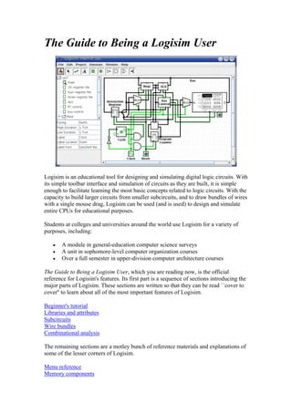
  • 1. The Guide to Being a Logisim User Logisim is an educational tool for designing and simulating digital logic circuits. With its simple toolbar interface and simulation of circuits as they are built, it is simple enough to facilitate learning the most basic concepts related to logic circuits. With the capacity to build larger circuits from smaller subcircuits, and to draw bundles of wires with a single mouse drag, Logisim can be used (and is used) to design and simulate entire CPUs for educational purposes. Students at colleges and universities around the world use Logisim for a variety of purposes, including: • A module in general-education computer science surveys • A unit in sophomore-level computer organization courses • Over a full semester in upper-division computer architecture courses The Guide to Being a Logisim User, which you are reading now, is the official reference for Logisim's features. Its first part is a sequence of sections introducing the major parts of Logisim. These sections are written so that they can be read ``cover to cover'' to learn about all of the most important features of Logisim. Beginner's tutorial Libraries and attributes Subcircuits Wire bundles Combinational analysis The remaining sections are a motley bunch of reference materials and explanations of some of the lesser corners of Logisim. Menu reference Memory components
  • 2. Logging Application preferences Project options Value propagation JAR libraries About the program Beginner's tutorial Next: Step 0: Orienting yourself Welcome to Logisim! Logisim allows you to design and simulate digital circuits. It is intended as an educational tool, to help you learn how circuits work. To practice using Logisim, let's build a XOR circuit - that is, a circuit that takes two inputs (which we'll call x and y) and outputs 1 if the inputs are the same and 0 if they are different. The following truth table illustrates. We might design such a circuit on paper. But just because it's on paper doesn't mean it's right. To verify our work, we'll draw it in Logisim and test it. As an added bonus, we'll get a circuit that's looks nicer than what you probably would draw by hand. Step 0: Orienting yourself Step 1: Adding gates Step 2: Adding wires Step 3: Adding text Step 4: Testing your circuit Enjoy your circuit-building!
  • 3. Next: Step 2: Adding wires Step 1: Adding gates Recall that we're trying to build the following circuit in Logisim. Building a circuit is easiest by inserting the gates first as a sort of skeleton for connecting wires into the circuit later. The first thing we're going to do is to add the two AND gates. Click on the AND tool in the toolbar ( , the next-to-last tool listed). Then click in the editing area where you want the AND gates to go. Be sure to leave plenty of room for stuff on the left. Notice the five dots on the left side of the AND gate. These are spots where wires can be attached. It happens that we'll just use two of them for our XOR circuit; but for other circuits, you may find that having more than two wires going to an AND gate is useful. Now add the other gates. First click on the OR tool ( ); then click where you want it. And select the NOT tool ( ) and put those two gates into the canvas.
  • 4. I left a little space between the NOT gates and the AND gates; if you want to, though, you can put them up against each other and save yourself the effort of drawing a wire in later. Now we want to add the two inputs x and y into the diagram. Select the input pin ( ), and place the pins down. You should also place an output pin ( ) next to the OR gate's output. (Again, though I'm leaving a bit of space between the OR gate and the output pin, you might choose to place them right next to each other.) If you decide you don't like where you placed something, then you can right-click (or control-click) anything in the canvas to view a pop-up menu. Choose Delete. You can also rearrange things using the select tool ( ). Next: Step 2: Adding wires Next: Step 3: Adding text
  • 5. Step 2: Adding wires After you have all the components blocked out on the canvas, you're ready to start adding wires. Select the wiring tool ( ). Then start dragging from one position to another in the canvas area, and a wire will start to appear between the two points. Wires in Logisim must be horizontal or vertical. To connect the upper input to the NOT gate and the AND gate, then, I added three different wires. Logisim automatically connects wires to the gates and to each other. This includes automatically drawing the circle at a T intersection as above, indicating that the wires are connected. T As you draw wires, you may see some blue or gray wires. Blue in Logisim indicates that the value at that point is ``unknown'', and gray indicates that the wire is not connected to anything. This is not a big deal temporarily. But by the time you finish your circuit, none of your wires should be blue or gray. (The unconnected legs of the OR gate will still be blue: That's fine.) If you do have a blue or a gray wire after you think everything ought to be connected, then something is going wrong. It's important that you connect wires to the right places. Logisim draws little dots on the components to indicate where wires ought to connect. As you proceed, you'll see the dots turn from blue to light or dark green. Once you have all the wires connected, all of the wires you inserted will themselves be light or dark green.
  • 6. Next: Step 3: Adding text Next: Step 4: Testing your circuit Step 3: Adding text Adding text to the circuit isn't necessary to make it work; but if you want to show your circuit to somebody (like a teacher), then some labels help to to communicate the purpose of the different pieces of your circuit. Select the text tool ( ). You can click on an input pin and start typing to give it a label. (It's better to click directly on the input pin than to click where you want the text to go, because then the label will move with the pin.) You can do the same for the output pin. Or you could just click any old place and start typing to put a label anywhere else. Next: Step 4: Testing your circuit Next: User's Guide
  • 7. Step 4: Testing your circuit Our final step is to test our circuit to ensure that it really does what we intended. Logisim is already simulating the circuit. Let's look again at where we were. Note that the input pins both contain 0s; and so does the output pin. This already tells us that the circuit already computes a 0 when both inputs are 0. Now to try another combination of inputs. Select the poke tool ( ) and start poking the inputs by clicking on them. Each time you poke an input, its value will toggle. For example, we might first poke the bottom input. When you change the input value, Logisim will show you what values travel down the wires by drawing them light green to indicate a 1 value or dark green (almost black) to indicate a 0 value. You can also see that the output value has changed to 1. So far, we have tested the first two rows of our truth table, and the outputs (0 and 1) match the desired outputs.
  • 8. By poking the switches through different combinations, we can verify the other two rows. If they all match, then we're done: The circuit works! To archive your completed work, you might want to save or print your circuit. The File menu allows this, and of course it also allows you to exit Logisim. But why quit now? Now that you are finished with tutorial, you can experiment with Logisim by building your own circuits. If you want to build circuits with more sophisticated features, then you should navigate through the rest of the help system to see what else you can do. Logisim is a powerful program, allowing you to build up and test huge circuits; this step-by-step process just scratches the surface. Next: User's Guide Libraries and Attributes In this section, we'll examine how to use the other two major regions of the Logisim window, the explorer pane and the attribute table. The explorer pane The attribute table Tool and component attributes Next: The explorer pane.
  • 9. The explorer pane Libraries contain components that can be dropped into circuits. They are displayed as folders in the explorer pane; to access a library's components, you have only to double-click the corresponding folder. Below, I have opened the Gates library and selected the NAND tool from it. You can see that Logisim now stands ready to add NAND gates into the circuit. If you look through the choices in the Gates library, you'll notice that there was no need for us to develop a XOR circuit earlier: It's built into Logisim. When you create a project, it automatically includes the Base and Gates libraries. But Logisim includes many other libraries, too: To load one, go to the Project menu, in the Load Library submenu, and choose Built-in Library.... A dialog box will appear allowing you to choose which libraries you want to add. If you choose Plexers, for example, then you will be able to add multiplexers, demultiplexers, and decoders. You can load as many libraries as you like. In the Load Library submenu, you can see that Logisim has three categories of libraries. • Built-in libraries are libraries that are distributed with Logisim. These are documented in the Library Reference. • Logisim libraries are projects built within Logisim and saved to the disk. You can develop a set of circuits in a single project (as described in the Subcircuits section of this guide) and then use that set of circuits as a library for another projects. • JAR libraries are libraries that are developed in Java but not distributed with Logisim. You can download JAR libraries that others have written, or you can write your own as described in the JAR Libraries section of this guide. Developing a JAR library is much more difficult than developing a Logisim library, but the components can be much fancier, including things like attributes and interaction with the user. The built-in libraries (other than Base)
  • 10. were written using the same API as JAR libraries can use, so they aptly demonstrate the range of functionality that the JAR libraries can support. When loading a JAR library, Logisim will prompt you to select the JAR file, and then it will prompt you to type a class name. This class name should be provided by whoever distributed the JAR file to you. To remove a library, choose Unload Library... from the Project menu. Logisim will prevent you from unloading libraries that contain components used in a circuit, that appear in the toolbar, or that are mapped to a mouse button. Incidentally, a library technically contains tools, not components. Thus, in the Base library you'll find the Poke Tool ( ), the Select Tool ( ), and other tools that don't correspond directly to individual components. Most libraries, though, contain only tools for adding individual components; all built-in libraries other than the Base library are like this. Next: The attribute table. The attribute table Many components have attributes, which are properties for configuring how the component behaves or appears. The attribute table is for viewing and displaying a component's attribute values. To select which component's attributes you wish to view, click the component using the Select tool ( ). (You can also right-click (or control-click) the component and choose Show Attributes from the popup menu. Also, manipulating a component via the Poke tool ( ) or the Text tool ( ) will display that component's attributes.) The below screen shot demonstrates what things look like after selecting the upper input of our XOR circuit and scrolling down to view the Label Font attribute.
  • 11. Note the pale teal (i.e., light blue) oval surrounding the pin, called a halo: This indicates whose attributes are displayed in the attribute table. To modify an attribute value, click on the value. The interface for modifying the attribute will depend on which attribute you are changing; in the case of the Label Font attribute, a dialog box will appear for selecting the new font; but some attributes (like Label) will allow you to edit the value as a text field, while others (like Label Location) will display a drop-down menu from which to select the value. Each component type has a different set of attributes; to learn what they mean, go to the relevant documentation in the Library Reference. Some components have attribute values that cannot be changed. One example of this is the AND gate's Gate Size attribute: As soon as you create an AND gate, is size is fixed. If you want an AND gate of a different size, then you'll need to change the attributes for the tool, which we'll discuss next. Next: Tool attributes. Tool attributes Every tool for adding components to a circuit also has a set of attributes, which are imparted to the components created by the tool, although the components' attributes may be changed later without affecting the tool's attributes. When you select a tool, Logisim will change the attribute table to display that tool's attributes. For example, suppose we want to create smaller AND gates. We've already seen that an AND gate's Gate Size attribute is not editable. But the Gate Size attribute is editable for the AND gate tool: To view and edit this attribute, click the tool's icon in the toolbar (or the explorer pane), and change its Gate Size attribute.
  • 12. Now, we can delete the two existing AND gates and add two new AND gates in their place. This time, they will be narrow. (If you chose to reduce the number of inputs to 3, the AND gate would not have vertical extension on the left side. But you'd also have to rewire the circuit so that the wires hit the AND gate's left side.) With some tools, the icon reflects some of the attributes' values. One example of this is with the Pin tool, whose icon faces the same way as its Facing attribute says. The tools in the toolbar each have a separate attribute set from the corresponding tools in the explorer pane. Thus, even though we changed the toolbar's AND tool to create narrow AND gates, the AND tool in the Gates library will still create wide AND gates unless you change its attributes too. In fact, the input pin and output pin tools in the default toolbar are both instances of the Base library's Pin tool, but the three attribute sets are different. The icon for the Pin tool is drawn as a circle or a square depending on the value of its ``Output?'' attribute. Logisim provides a handy shortcut for changing the Facing attribute that controls the direction in which many components face: Typing an arrow key while that tool is selected automatically changes the direction of the component. Next: User's Guide.
  • 13. Subcircuits As you build circuits that are more and more sophisticated, you will want to build smaller circuits that you can use multiple times in larger circuits. In Logisim, such a smaller circuit that is used in a larger circuit is called a subcircuit. If you're familiar with computer programming, you're familiar with the subprogram concept (called subroutines, functions, or methods in different languages). The subcircuit concept is analogous to the concept in computer programming, and it is used for the same purposes: To break a large job into bite-sized pieces, to save the effort of defining the same concept multiple times, and to facilitate debugging. Creating circuits Using subcircuits Debugging subcircuits Logisim libraries Next: Creating circuits. Creating circuits Every Logisim project is actually a library of circuits. In its simplest form, each project has only one circuit (called "main" by default), but it is easy to add more: Select Add Circuit... from the Project menu, and type any name you like for the new circuit you want to create. Suppose we want to build a 1x2 multiplexer named "1x2 MUX." After adding the circuit, Logisim will look like this. In the explorer pane, you can now see that the project now contains two circuits, "main", and "1x2 MUX." Logisim draws a magnifying glass over the icon of the circuit currently being viewed; the current circuit name also appears in the window's title bar.
  • 14. After editing the circuit to appear like a 1x2 multiplexer, we might end up with the following circuit. Next: Using subcircuits. Using subcircuits Now suppose we want to build a 2x4 multiplexer using instances of our 1x2 multiplexer. Of course, we would first create a new circuit, which we'll call "2x4 MUX." To add 1x2 multiplexers into our circuit, we click the 1x2 MUX circuit once in the explorer pane to select it as a tool, and then we can add copies of it, represented as boxes, by clicking within the canvas. If you click the 1x2 MUX circuit twice in the explorer pane, then the window would switch to editing the 1x2 MUX circuit instead. After building up the circuit, we end up with the following.
  • 15. Our circuit for a 2x4 multiplexer uses three copies of the 1x2 multiplexer, each drawn as a box with pins along the side. The pins on this box correspond to the input and output pins in the 1x2 MUX circuit. The two pins on the west side of the box correspond to the two pins that face east in the 1x2 MUX circuit; the pin on the box's east side corresponds to the 1x2 MUX's west-facing pin (which happens to be an output pin); and the pin on the box's south side corresponds to the 1x2 MUX's north- facing pin. The order of the two pins on the box's west side correspond to the same top-down ordering that apears in the subcircuit. (If there were several pins on the box's north or south side, they would correspond to the same left-right order in the subcircuit.) If the pins in the subcircuit's layout have labels associated with them, then Logisim will display that label in a tip (that is, a temporary text box) when the user hovers the mouse over the corresponding location of the subcircuit component. (If you find these tips irritating, you can disable them via the Project Options window's Canvas tab.) Several other components will display these tips, too: For some of the pins of a built- in flip-flop, for example, hovering over it explains what that pin does. Incidentally, every pin to a circuit must be either an input or an output. Many manufactured chips have pins that behave as an input in some situations and as an output in others; you cannot construct such chips within Logisim.
  • 16. Logisim will maintain different state information for all subcircuits appearing in a circuit. For example, if a circuit contains a flip-flop, and that circuit is used as a subcircuit several times, then each subcircuit's flip-flop will have its own value when simulating the larger circuit. Now that we have the 2x4 multiplexer defined, we can now use it in other circuits. Logisim has no limits on how deeply circuits can be nested - though it will object to nesting circuits within themselves! Note: There's nothing wrong with editing a circuit that is being used as a subcircuit; in fact, this is quite common. Be aware, though, that any changes to a circuit's pins (adding, deleting, or moving them) will rearrange them also in the containing circuit. Thus, if you change any pins in a circuit, you will also need to edit any circuits using it as a subcircuit. Next: Debugging subcircuits. Debugging subcircuits As you test larger circuits, you will likely find bugs. To nail down what's going wrong, exploring what's going on in the subcircuits while running the overall circuit can help. From viewing the overall circuit, you can do this by bringing up the subcircuit's popup menu (right-click or control-click its box). Then choose the View option. After choosing this, the view will switch to the subcircuit.
  • 17. Notice that the pins' values in the subcircuit match the values being sent to them in its containing circuit. While in the subcircuit, you can change it however you want; any changes to pins' values will be propagated within the containing circuit. (If you attempt to toggle a pin using the Poke Tool, Logisim will pop up a dialog box asking whether you want to create a new state; responding Yes will divorce the state viewed with the subcircuit from the outer circuit's state, while responding No will cancel the toggle request.) Once you have completed viewing and/or editing the parent circuit either by double- clicking it in the explorer pane, or via the Go Out To State submenu of the Simulate menu. Next: Logisim libraries. Logisim libraries Every Logisim project is automatically a library that can be loaded into other Logisim projects: Just save it into a file and then load the library within another project. All of the circuits defined in the first project will then be available as subcircuits for the second. This feature allows you to reuse common components across projects and to share favorite components with your friends (or students). Each project has a designated "main circuit," which can be changed to refer to the current circuit via the Set As Main Circuit option in the Project menu. The only significance of this is that the main circuit is the one that is displayed when you first open the project. The default name of the circuit in a newly created file ("main") has no significance at all, and you can feel free to delete or rename that circuit. With a loaded Logisim library, you are allowed to view circuits and manipulate their states, but Logisim will prevent you from altering them. If you want to alter a circuit in a loaded Logisim library, then you need to open it separately within Logisim. As soon as you save it, the other project should
  • 18. automatically load the modified version immediately; but if it does not, you can right- click the library folder in the explorer pane and select Reload Library. Next: User's Guide. Wire bundles In simple Logisim circuits, most wires carry only one bit; but Logisim also allows you to create wires that bundle together multiple bits. The number of bits traveling along a wire is that wire's bit width. Creating bundles Splitters Wire colors Next: Creating bundles. Creating bundles Every input and output on every component in the circuit has a bit width associated with it. Many of Logisim's built-in components include attributes allowing you to customize the bit widths of their inputs and outputs. The below screen shot illustrates a simple circuit for finding the bitwise AND of two three-bit inputs; each pin has its Bit Width attribute customized for dealing with three- bit data, as with the pictured AND gate attributes. Notice that the input and output pins are drawn with three bits, and the output is the bitwise AND of the inputs. For components, all inputs and outputs must have their bit widths defined. In contrast, a wire's bit width is undefined: Instead, the wire's width adapts to the components to which it is attached. If a wire connects two components demanding different bit widths, Logisim will complain of ``Incompatible widths'' and indicate the offending locations in orange. In the below, the output pin's Bit Width attribute has been
  • 19. changed to 1, and so Logisim complains that the wire cannot connect a three-bit value to a one-bit value. Wires that connect incompatible locations (drawn in orange) do not carry values. For single-bit wires, you can see at a glance what value it is carrying because Logisim colors the wire light or dark green depending the value. It does not display values for multi-bit wires: They are simply black. You can, though, probe a wire by clicking it using the poke tool ( ). This probing feature is helpful for debugging circuits using wire bundles. Next: Splitters. Splitters When you work with multi-bit values, you will often want to route different bits in different directions. The Base library's splitter tool ( allows you to accomplish this. For example, suppose we want to build a circuit taking an eight-bit input and outputting the AND of its two nibbles (the upper four bits and the lower four bits). We will have an eight-bit value coming from the input pin, and we want to split that into two four-bit values. In the below circuit, we have used a splitter to accomplish this.
  • 20. In this example, the splitter happens to actually split an incoming value into multiple outgoing values. But splitters can also combine multiple values into a single value. In fact, they are non-directional: They can send values one way at one time and another way later, and they can even do both at the same time, as in the below example where two values are fed rightward and the middle value feeds leftward. The key to understanding splitters is their attributes. In the following, the term split end refers to one of the multiple wires on one side, while the term combined end refers to the single wire on the other side. • The Facing attribute tells where the split ends should be relative to the combined end. This cannot be changed once a splitter is dropped into the circuit.
  • 21. • The Fan Out attribute specifies how many split ends there are. This also cannot be changed once a splitter is dropped into the circuit. • The Bit Width attribute specifies the bit width of the combined end. • The Bit x attribute says which split end corresponds to bit x of the combined end. If multiple bits correspond to the same split end, then their relative ordering will be the same as in the combined end. Logisim splitters cannot have a bit from the combined end correspond to multiple split ends. Note that any change to the Fan Out or Bit Width attributes will reset all Bit x attributes so that they will distribute the bits of the combined value as evenly as possible among the split ends. Next: Wire colors. Wire colors We are now in a position to summarize the full rainbow of colors that Logisim wires can take on. The following little circuit illustrates all of them at once. • Gray: The wire's bit width is unknown. This occurs because the wire is not attached to any components' inputs and outputs. (All inputs and outputs have a defined bit width.) • Blue: The wire is for carrying a one-bit value, but the value it is carrying is not known. In the above example, this is occurring because the NOT gate's input is unknown, and so its output is also unknown. • Dark green: The wire is carrying a one-bit 0 value. • Bright green: The wire is carrying a one-bit 1 value. • Black: The wire is carrying a multi-bit value. Some or all of the bits may not be specified. • Red: The wire is carrying an error value. This usually arises because conflicting values on the wire. (The other possibility would be that a library component is programmed to emit an error value for another reason; in the built-in libraries, though, error values arise only from propagating other error values.) In the above example, we have one input pin placing a 0 on the wire and another placing a 1 on the wire, causing a conflict. Multi-bit wires will turn red when any of the bits carried are error values.
  • 22. • Orange: The components attached to the wire do not agree in bit width. An orange wire is effectively "broken": It does not carry values between components. Next: User's Guide. Combinational analysis All circuits fall into one of two well-known categories: In a combinational circuit, all circuit outputs are a strict combination of the current circuit inputs, whereas in a sequential circuit, some outputs may depend on past inputs (the sequence of inputs over time). The category of combinational circuits is the simpler of the two. Practitioners use three major techniques for summarizing the behavior of such circuits. • logic circuits • Boolean expressions, which allow an algebraic representation of how the circuit works • truth tables, which list all possible input combinations and the corresponding outputs The Combinational Analysis module of Logisim allows you to convert between these three representations in all directions. It is a particularly handy way of creating and understanding circuits with a handful of one-bit inputs and outputs. Opening Combinational Analysis Editing the truth table
  • 23. Creating expressions Generating a circuit Next: Opening Combinational Analysis. Opening Combinational Analysis The bulk of the Combinational Analysis module is accessed through a single window of that name allowing you to view truth tables and Boolean expressions. This window can be opened in two ways. Via the Window menu Select Combinational Analysis, and the current Combinational Analysis window will appear. If you haven't viewed the window before, the opened window will represent no circuit at all. Only one Combinational Analysis window exists within Logisim, no matter how many projects are open. There is no way to have two different analysis windows open at once. Via the Project menu From a window for editing circuits, you can also request that Logisim analyze the current circuit by selecting the Analyze Circuit option from the Project menu. Before Logisim opens the window, it will compute Boolean expressions and a truth table corresponding to the circuit and place them there for you to view. For the analysis to be successful, each input must be attached to an input pin, and each output must be attached to an output pin. Logisim will only analyze circuits with at most eight of each type, and all should be single-bit pins. Otherwise, you will see an error message and the window will not open. In constructing Boolean expressions corresponding to a circuit, Logisim will first attempt to construct a Boolean expressions corresponding exactly to the gates in the circuit. But if the circuit uses some non-gate components (such as a multiplexer), or if the circuit is more than 100 levels deep (unlikely), then it will pop up a dialog box telling you that deriving Boolean expressions was impossible, and Logisim will instead derive the expressions based on the truth table, which will be derived by quietly trying each combination of inputs and reading the resulting outputs. After analyzing a circuit, there is no continuing relationship between the circuit and the Combinational Analysis window. That is, changes to the circuit will not be reflected in the window, nor will changes to the Boolean expressions and/or truth table in the window be reflected in the circuit. Of course, you are always free to analyze a circuit again; and, as we will see later, you can replace the circuit with a circuit corresponding to what appears in the Combinational Analysis window.
  • 24. Limitations Logisim will not attempt to detect sequential circuits: If you tell it to analyze a sequential circuit, it will still create a truth table and corresponding Boolean expressions, although these will not accurately summarize the circuit behavior. (In fact, detecting sequential circuits is provably impossible, as it would amount to solving the Halting Problem. Of course, you might hope that Logisim would make at least some attempt - perhaps look for flip-flops or cycles in the wires - but it does not.) As a result, the Combinational Analysis system should not be used indiscriminately: Only use it when you are indeed sure that the circuit you are analyzing is indeed combinational! Logisim will make a change to the original circuit that is perhaps unexpected: The Combinational Analysis system requires that each input and output have a unique name that conforming to the rules for Java identifiers. (Roughly, each character must either a letter or a digit, and the first character must be a letter. No spaces allowed!) It attempts to use the pins' existing labels, and to use a list of defaults if no label exists. If an existing label doesn't follow the Java-identifier rule, then Logisim will attempt to extract a valid name from the label if at all possible. Incidentally, the ordering of the inputs in the truth table will match their top-down ordering in the original circuit, with ties being broken in left-right order. (The same applies to the ordering of outputs.) Next: Editing the truth table. Editing the truth table On opening the Combinational Analysis window, you will see that it consists of five tabs.
  • 25. This page describes the first three tabs, Inputs, Outputs, and Table. The next page of the guide describes the last two tabs, Expression and Minimized. The Inputs and Outputs tabs The Inputs tab allows you to view and edit the list of inputs. To add new inputs, type it in the field at the pane's bottom, and click Add. If you want to rename an existing input, select it in the list in the pane's upper left region; then type the name and click Rename. To remove an input, select it from the list and click Remove. You can also reorder the inputs (which affects the order of columns in the truth table and in the generated circuit) using the Move Up or Move Down buttons on an input. All actions affect the truth table immediately. The Outputs tab works in exactly the same way as the Inputs tab, except of course it works with the list of outputs instead. The Table tab The only item under the Table tab is the current truth table, diagrammed in the conventional order, with inputs constituting the columns on the left and outputs constituting the columns on the right. You can edit the current values appearing in the output columns by clicking on the value of interest. The values will cycle through 0, 1, and x (representing a "don't care"). As we'll see on the next page, any don't-care values allow the computation of minimized expressions some flexibility.
  • 26. You can also navigate and edit the truth table using the keyboard. And you can copy and paste values using the clipboard. The clipboard can be transferred to any application supporting tab-delimited text (such as a spreadsheet). If the truth table is based on an existing circuit, you may see some pink squares in the output columns with "!!" in them. These correspond to errors that occurred while calculating the value for that row - either the circuit seemed to be oscillating, or the output value was an error value (which would be pictured as a red wire in the Logisim circuit). Hovering your mouse over the entry should bring up a tool tip describing which type of error it was. Once you click on the error entry, you will be in the 0-1-x cycle; there is no way to go back. Next: Creating expressions. Creating expressions For each output variable, the Combinational Analysis window maintains two structures - the relevant column of the truth table, and a Boolean expression - specifying how each output relates to its input. You can edit either the truth table or the expression; the other will automatically change as necessary to keep them consistent. As we will see on the next page, the Boolean expressions are particularly useful because the Combinational Analysis window will use these when told to build a circuit corresponding to the current state. You can view and edit the expressions using the window's last two tabs, the Expression tab and the Minimized tab.
  • 27. The Expression tab The Expression tab allows you to view and edit the current expression associated with each output variable. You can select the output expression you want to view and edit using the selector labeled "Output:" at the pane's top. Just below the selector will appear the expression formatted in a particularly common notation, where an OR is represented as addition, an AND is represented as multiplication, and a NOT is denoted with a bar above the portion affected by the NOT. The text pane below this displays the same information in ASCII form. Here, a NOT is represented with a tilde ('~'). You can edit the expression in the text pane and click the Enter button to make it take effect; doing this will also update the truth table to make it correspond. The Clear button clears the text pane, and the Revert button changes the pane back to representing the current expression. Note that your edited expression will be lost if you edit the truth table. In addition to multiplication and addition standing for AND and OR, an expression you type may contain any of C/Java logical operators, as well as simply the words themselves. highest precedence ~ ! NOT (none) & && AND ^ XOR
  • 28. lowest precedence + | || OR The following examples are all valid representations of the same expression. You could also mix the operators. ~a (b + c) !a && (b || c) NOT a AND (b OR c) In general, parentheses within a sequence of ANDs (or ORs or XORs) do not matter. (In particular, when Logisim creates a corresponding circuit, it will ignore such parentheses.) The Minimized tab The final tab displays a minimized sum-of-products expression corresponding to a column of the truth table. You can select which output's minimized expression you want to view using the selector at top. If there are four or fewer inputs, a Karnaugh map corresponding to the variable will appear below the selector. You can click the Karnaugh map to change the corresponding truth table values. The Karnaugh map will also display the currently selected terms for the minimized expression as solid semitransparent rounded rectangles. Below this is the minimized expression itself, formatted as in the Expression tab's display. If there are more than four inputs, the Karnaugh map will not appear; but the minimized expression will still be computed. (Logisim uses the Quine-McCluskey algorithm to compute the minimized expression. This is equivalent to a Karnaugh map, but it applies to any number of input variables.)
  • 29. The Set As Expression button allows you to select the minimized expression as the expression corresponding to the variable. This will generally not be necessary, as edits to the truth table result in using the minimized expression for the changed column; but if you enter an expression through the Expression tab, this can be a convenient way to switch to the corresponding minimized expression. Next: Generating a circuit. Generating a circuit The Build Circuit button will construct a circuit whose gates correspond to the currently chosen expressions for each output. The circuit's inputs and outputs will be displayed in top-down order corresponding to how they appear under the Inputs and Outputs tabs. Generally speaking, the constructed circuit will be attractive; and, indeed, one application of Logisim's Combinational Analysis module is to beautify poorly drawn circuits. Still, as with any automatic formatting, it will not express the structural details that a human-drawn circuit would. When you click the Build Circuit button, a dialog box will appear prompting you to choose which project where you want the circuit and the name you wish to give it. If you type the name of an existing circuit, then that circuit will be replaced (after Logisim prompts you to confirm that you really want to do this). The Build Circuit dialog includes two options. The Use Two-Input Gates Only option specifies that you want all gates constructed to have two inputs. (NOT gates, of course, constitute an exception to this rule.) The Use NAND Gates Only option specifies that you would like it to translate the circuit into one using only NAND gates. You can select both options if you want to use only two-input NAND gates. Logisim cannot construct a NAND-only circuit for an expression containing any XOR operators. This option will therefore be disabled if any outputs' expressions contain XORs. Next: User's Guide. Memory components The RAM and ROM components are two of the more useful components in Logisim's built-in libraries. However, because of the volume of information they can store, they are also two of the most complex components. Documentation about how they work within a circuit can be found on the RAM and ROM pages of the Library Reference. This section of the User's Guide explains the interface allowing the user to view and edit memory contents. Poking memory Pop-up menus and files Logisim's integrated hex editor
  • 30. Next: Poking memory. Poking memory You can manipulate the contents of memory using the Poke Tool, but the interface for this is severely limited by space constraints: For more than the simplest editing, you will probably find the integrated hex editor far more convenient. Nonetheless, to view and edit values within the circuit, the Poke Tool has two modes of operation: You can edit the address displayed, and you can edit an individual value. To edit the address displayed, click outside the display rectangle. Logisim will draw a red rectangle around the top address. • Typing hexadecimal digits will change the top address accordingly. • Typing the Enter key will scroll down one line. • Typing the Backspace key will scroll up one line. • Typing the space bar will scroll down one page (four lines). To edit a particular value, click the value within the display rectangle. Logisim will draw a red rectangle around that address. • Typing hexadecimal digits will change the value at the address currently being edited. • Typing the Enter key will move to editing the value just below it in the display (down one line). • Typing the Backspace key will move to editing the value at the previous address. • Typing the space bar will move to editing the value at the following address. Next: Pop-up menus and files. Pop-up menus and files The pop-up menu for memory includes four options in addition to the options common to all components: • Edit Contents: Bring up a hex editor for editing the contents of memory. • Clear Contents: Resets all values in memory to 0. • Load Image...: Resets all values in memory based on the values found in a file using the format described below. • Save Image...: Stores all values in memory into a file using the format described below. The file format used for image files is intentionally simple; this permits you to write a program, such as an assembler, that generates memory images that can then be loaded into memory. As an example of this file format, if we had a 256-byte memory whose
  • 31. first five bytes were 2, 3, 0, 20, and -1, and all subsequent values were 0, then the image would be the following text file. v2.0 raw 02 03 00 14 ff The first line identifies the file format used (currently, there is only one file format recognized). Subsequent values list the values in hexadecimal, starting from address 0; you can place several such values on the same line. Logisim will assume that any values unlisted in the file are zero. The image file can use run-length encoding; for example, rather than list the value 00 sixteen times in a row, the file can include 16*00 rather than repeat 00 sixteen times. Notice than the number of repetitions is written in base 10. Files produced by Logisim will use run-length encoding for runs of at least four values. Next: Hex editor. Hex editor Logisim includes an integrated hex editor for viewing and editing the contents of memory. To access it, bring up a pop-menu for the memory component and select Edit Contents.... For ROM components, which have the memory contents as part of the attribute value, you can alternatively access the hex editor by clicking the corresponding attribute value. The numbers in italics at left display memory addresses, written in hexadecimal. The other numbers display values starting from that memory address; the hex editor may display four, eight, or sixteen values per line, depending on what fits in the window. To help with counting, each group of four values has a larger space between. You can navigate through memory using the scroll bar or using the keyboard (the arrow keys, home, end, page up, and page down). Typing hexadecimal characters will alter the currently selected value. You can select a range of values by dragging the mouse, shift-clicking the mouse, or navigating through memory with the keyboard while depressing the shift key. Values
  • 32. may be copied and pasted using the Edit menu; the clipboard can also be transferred into other applications. Next: User's Guide. Logging In testing a large circuit, and for documenting a circuit's behavior, a log of past circuit behavior. This is the purpose for Logisim's logging module, which allows you to select components whose values should be logged; optionally, you can specify a file into which the log should be placed. Note: The logging module is in alpha phase; it may be buggy, and it is subject to significant changes in the future. While bug reports and suggestions are welcome for all of Logisim, they are particularly welcome concerning this relatively new feature. If you do not send comments, then it will likely not change. You can enter the logging module via the Logging... option from the Simulate menu. It brings up a window with three tabs. We will discuss each of these tabs separately. The Selection tab The Table tab The File tab Each project has only one logging window; when you switch to viewing another circuit within the project, the logging window switches automatically to logging the
  • 33. other circuit instead. That is, it does this unless you are moving up or down within the same simulation, in which case the logging module does not change. Note that when the logging module switches to logging another simulation, it will cease any logging into a file. Should you switch back to the simulation again, it will remember the configuration for that simulation, but you will need to re-enable the file logging manually. Next: The Selection tab. The Selection tab The Selection tab allows you to select which values should be included in the log. The window below corresponds to the following circuit. The tab is divided into three vertical areas. The first (leftmost) is a list of all components in the circuit whose values can be logged. Among the built-in libraries, the following types of components support logging.
  • 34. Base library: Pin, Probe, and Clock components Memory library: All components For components with labels associated with them, their names correspond to the labels; other components' names specify their type and their location within the circuit. Any subcircuits will also appear in the list; they cannot be selected for logging, but eligible components within them can be. Note that the RAM component requires you to choose which memory address(es) should be logged; it allows logging only for the first 256 addresses. The last (rightmost) vertical area lists those components that have been selected. Also, it indicates the radix (base) in which the component's multi-bit values will be logged; the radix does not have a significant effect on one-bit values. The middle column of buttons allows the manipulation of the items within the selection. • Add adds the currently selected item(s) on the left side into the selection. • Change Radix cycles the radix for the currently selected component in the selection between 2 (binary), 10 (decimal), and 16 (hexadecimal). • Move Up moves the currently selected component in the selection forward one spot. • Move Down moves the currently selected component in the selection back one spot. • Remove removes the currently selected component in the selection. Next: The Table tab. The Table tab The Table tab displays the current log graphically.
  • 35. The table contains a column for each component in the selection. Each row in the selection displays a snapshot of the simulation after a propagation of values has completed. Any duplicate rows are not added into the log. Note that only the most recent 400 rows are displayed. Some rows may have empty entries if the corresponding component was not in the selection at the time that the row was computed. The displayed table is for review only; it is not interactive. Next: The File tab. The File tab The File tab allows you to specify a file into which the log should be placed.
  • 36. At the top is an indicator of whether file logging is in progress and a button for enabling or disabling it. (Note that you cannot enable it until a file is selected below.) The button allows you to pause and restart file entry. When you switch in the project window to viewing another simulation, the file logging is automatically halted; if you return to the original one and want logging to continue, you will need to re-enable the file logging manually using the button at top. In the middle is an indicator of what file is being logged to. To change it, use the Select... button. On selecting a file, file logging will automatically start. If you select a pre-existing file, Logisim will ask whether you want to overwrite the file or append the new entries onto the end. At bottom you can control whether a header line should be placed into the file indicating which items are in the selection. If header lines are added, then a new header line will be placed into the file whenever the selection changes. File format Entries are placed into the file in tab-delimited format corresponding closely to what appears under the Table tab. (One difference is that any header lines will give the full path to components lying in subcircuits.) The format is intentionally simple so that you can feed it into another program for processing, such as a Python/Perl script or a spreadsheet program. So that a script can process the file at the same time as Logisim is running, Logisim will flush the new records onto the disk every 500 ms. Note that Logisim may also intermittently close and later re-open the file during the simulation, particularly if several seconds have elapsed without any new records being added.