Method and apparatus for intelligent management of a network element
US20080313598
1. US 20080313598A1
(19) United States
(12) Patent Application Publication (10) Pub. No.: US 2008/0313598 A1
Frasher et al. (43) Pub. Date: Dec. 18, 2008
(54)
(76)
(21)
(22)
TECHNIQUE FOR MANAGING THE
PROCESS OF DEVELOPING SOFTWARE
Thomas A. Frasher, Sunnyvale,
CA (US); Todd M. Fitch, Santa
Clara, CA (US)
Inventors:
Correspondence Address:
PVF -- INTUIT, INC.
c/o PARK, VAUGHAN & FLEMING LLP
2820 FIFTH STREET
DAVIS, CA 95618-7759 (US)
App1.No.: 11/818,178
Filed: Jun. 12, 2007
Publication Classi?cation
(51) Int. Cl.
G06F 9/44 (2006.01)
(52) US. Cl. ...................................................... .. 717/101
(57) ABSTRACT
A system that manages development ofsoftware is described.
During operation, this system aggregates status information
and requirement information as a function oftime, Where the
status information speci?es the status of the development of
the softWare and the requirement information speci?es target
requirements for the softWare. Next, the system dynamically
determines a project estimate for the development of the
softWare based on the status information and the requirement
information.
/“ 200
AGGREGATE STATUS INFORMATION AS A FUNCTION OF TIME, WHERE THE
STATUS INFORMATION SPECIFIES A STATUS OF DEVELOPMENT OF SOFTWARE
7
AGGREGATE REQUIREMENT INFORMATION AS A FUNCTION OF TIME, WHERE
THE REQUIREMENT INFORMATION SPECIFIES TARGET REQUIREMENTS FOR
THE SOFTWARE
V DYNAMICALLY DETERMINE A PROJECT ESTIMATE FOR THE DEVELOPMENT OF
THE SOFTWARE BASED ON THE STATUS INFORMATION AND THE
REQUIREMENT INFORMATION
7
GENERATE A FIRST MULTI-DIMENSIONAL VECTOR CORRESPONDING
TO AT LEAST A PORTION OF THE STATUS INFORMATION
,
GENERATE A SECOND MULTI-DIMENSIONAL VECTOR
CORRESPONDING TO AT LEAST A PORTION OF THE REQUIREMENT
INFORMATION
CALCULATE A DIFFERENCE BETWEEN THE FIRST MULTI
DIMENSIONAL VECTOR AND THE SECOND MULTI-DIMENSIONAL
VECTOR
3. Patent Application Publication Dec. 18, 2008 Sheet 2 0f 4 US 2008/0313598 A1
/_ 200
AGGREGATE STATUS INFORMATION AS A FUNCTION OF TIME, WHERE THE
STATUS INFORMATION SPECIFIES A STATUS OF DEVELOPMENT OF SOFTWARE
212
I
AGGREGATE REQUIREMENT INFORMATION AS A FUNCTION OF TIME, WHERE
THE REQUIREMENT INFORMATION SPECIFIES TARGET REQUIREMENTS FOR
THE SOFTWARE
m
I
rDYNAMICALLY DETERMINE A PROJECT ESTIMATE FOR THE DEVELOPMENT OF I
THE SOFTWARE BASED ON THE STATUS INFORMATION AND THE
REQUIREMENT INFORMATION
2M
GENERATE A FIRST MULTI-DIMENSIONAL VECTOR CORRESPONDING
TO AT LEAST A PORTION OF THE STATUS INFORMATION
2E
GENERATE A SECOND MULTI-DIMENSIONAL VECTOR
CORRESPONDING TO AT LEAST A PORTION OF THE REQUIREMENT
INFORMATION
2_l_§
CALCULATE A DIFFERENCE BETWEEN THE FIRST MULTI
DIMENSIONAL VECTOR AND THE SECOND MULTI-DIMENSIONAL
VECTOR
m
FIG. 2
4. Patent Application Publication
K310
PROCESSOR(S)
322
314
USER INTERFACE
_ 316
318 " ‘ KEYBOARD
312
COMMUNICATION
INTERFACE
SOFTWARE MODULE(S)
Dec. 18, 2008 Sheet 3 0f4 US 2008/0313598 A1
K 300
MEMORY 324
OPERATING SYSTEM f 326
COMMUNICATION MODULE f 328
AGGREGATION MODULE f 330
STATUS INFORMATION f 332
334-1
PROJECT A /
334-2
PROJECT B I
.
.
. 3 63
PROJECT ESTIMATION MODULE f
338
WEIGHTS f
(OPTIONAL) 340
REQUIREMENT INFORMATION f
342-1
TARGET A f
342-2
TARGET B J
O
.
. 344
VECTORS f
346
PROJECT EsTIMATEs f
34:;
RECOMMENDED MODIFICATIONS f
f 350
FIG. 3
5.
6. US 2008/0313598 A1
TECHNIQUE FOR MANAGING THE
PROCESS OF DEVELOPING SOFTWARE
BACKGROUND
[0001] The present invention relates to techniques for man
aging the process of developing software.
[0002] Many software applications are becoming increas
ingly more complicated, and thus, more time consuming and
dif?cult to develop. Simultaneously, customers and investors
now expect development of software to be a predictable pro
cess that meets design targets on-time and within budgetary
constraints. Consequently, companies are increasingly
emphasiZing project management during the development of
software.
[0003] Unfortunately, the software development process is
also becoming increasingly dynamic, with frequent changes
being made to design targets and available engineering
resources during a given project. It is often dif?cult to keep
track of all of these changes and to accurately manage the
resources needed to meet the design targets using existing
project management tools.
SUMMARY
[0004] One embodiment of this invention provides a sys
tem that manages development of software. During opera
tion, this system aggregates status information and require
ment information as a function of time, where the status
information speci?es the status of the development of the
software and the requirement information speci?es target
requirements for the software. Next, the system dynamically
determines a project estimate for the development of the
software based on the status information and the requirement
information.
[0005] In some embodiments, the dynamic determination
involves generating a ?rst multi-dimensional vector corre
sponding to at least a portion of the status information and
generating a second multi-dimensional vector corresponding
to at least a portion ofthe requirement information. Then, the
system calculates a difference between the ?rst multi-dimen
sional vector and the second multi-dimensional vector. Note
that generation of the ?rst multi-dimensional vector and/or
the second multi-dimensional vector may involve using dif
ferent weights for two variables in at least the portion of the
status information and/or the requirement information.
[0006] In some embodiments, the status information
includes: time stamps, a number ofreported bugs, features to
be developed for the software, a number of development
engineers, a number of hours worked developing the soft
ware, a number of hours worked testing the software, and/or
a number of lines of code in the software.
[0007] In some embodiments, the requirement information
includes: time stamps, a targeted completion time, budgetary
constraints, user requirements, one or more quality metrics
for the software, one or more operating environments, and/or
a number ofusers. For example, the requirement information
may include a con?dence region surrounding an end point in
the development.
[0008] In some embodiments, the project estimate includes
an estimated completion time and/or recommended modi?
cations to development resources to meet a targeted comple
tion time. These recommended modi?cations may include
changes to a number of development engineers and/or
changes to features to be developed for the software.
Dec. 18,2008
[0009] In some embodiments, the project estimate includes
recommended modi?cations to user requirements and/or rec
ommended modi?cations to a quality metric for the software.
These recommended modi?cations may include changes to
features to be developed for the software and/or changes to
the con?dence region surrounding an end point in the devel
opment.
[0010] In some embodiments, the aggregation ofthe status
information and/or the requirement information involves
adding or subtracting variables as a function of time.
[0011] In some embodiments, the project estimate is based
on a rate at which development engineers develop a given
feature for the software and/or a rate at which development
engineers correct a given reported bug in the software.
[0012] Another embodiment provides a method for man
aging the development ofsoftware. This methodmay perform
at least some of the above-described operations.
[0013] Another embodiment provides a computer program
product foruse in conjunctionwiththe system. This computer
program product may include instructions corresponding to
at least some of the above-described operations.
BRIEF DESCRIPTION OF THE FIGURES
[0014] FIG. 1A is a graph illustrating progress vectors and
a target vector during the software development process in
accordance with an embodiment of the present invention.
[0015] FIG. 1B is a graph illustrating a derived vector and a
correction vector during the software development process in
accordance with an embodiment of the present invention.
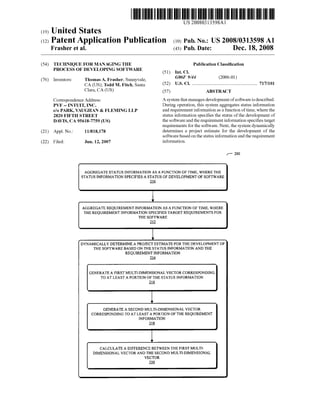
[0016] FIG. 2 is a ?ow chart illustrating a method for man
aging development of software in accordance with an
embodiment of the present invention.
[0017] FIG. 3 is a block diagram illustrating a computer
system in accordance with an embodiment of the present
invention.
[0018] FIG. 4 is a block diagram illustrating a data structure
in accordance with an embodiment of the present invention.
[0019] FIG. 5 is a block diagram illustrating a data structure
in accordance with an embodiment of the present invention.
[0020] Note that like reference numerals refer to corre
sponding parts throughout the drawings.
DETAILED DESCRIPTION
[0021] The following description is presentedto enable any
person skilled in the art to make and use the invention, and is
provided in the context of a particular application and its
requirements. Various modi?cations to the disclosed embodi
ments will be readily apparent to those skilled in the art, and
the general principles de?ned herein may be applied to other
embodiments and applications without departing from the
spirit and scope of the present invention. Thus, the present
invention is not intended to be limited to the embodiments
shown, but is to be accorded the widest scope consistent with
the principles and features disclosed herein.
[0022] Embodiments of a computer system, a method, and
a computer program product (i.e., software) for use with the
computer system are described. These systems, software, and
processes may be used to manage development of software
(such as programs or modules). In particular, the computer
system may aggregate status information (which speci?es a
status of the development of the software) and requirement
information (which speci?es target requirements for the soft
ware) as a function oftime. Using the status information and
7. US 2008/0313598 Al
the requirement information, the computer system dynami
cally determines a project estimate for the development ofthe
software. For example, the computer system may generate
multi-dimensional vectors corresponding, respectively, to at
least a portion of the status information and the requirement
information. Then, the computer system may calculate a dif
ference betWeen these multi-dimensional vectors.
[0023] These techniques may be implemented as a stand
alone softWare application, or as a program module or sub
routine in another application. Furthermore, at least a portion
of the program may be con?gured to execute on a client
computer (such as a personal computer, a laptop computer,
cell phone, PDA, or other device capable of manipulating
computer readable data) or remotely from a client computer
via computing systems over a netWork (such as the Internet,
Intranet, LAN, WAN, MAN, or combination ofnetWorks, or
other technology enabling communication betWeen comput
ing systems). Therefore, the information used to manage
development of the softWare may be stored locally (for
example, on a local computer) and/or remotely (for example,
on a computer or server that is accessed via a network).
[0024] We noW describe embodiments of systems and pro
cesses for managing the development of softWare. Quality
assurance and engineering managers often attempt to deter
mine the needs of a development project, including: the
amount of time, resources, and/or expenses associated With
completing a speci?c number oftasks. In the discussion that
folloWs, targeting techniques are used to assist these manag
ers in this process, thereby helping them ansWer a question
such as: can an engineering or quality-assurance goal be
achieved given the current status ofand resources available to
the development project?
[0025] These targeting techniques alloW the question to be
re-expressed as a multivariate, dynamic problem, Which can
be repeatedly solved as variables and/or design goals or tar
gets change. The resulting project estimates may assist the
quality assurance and engineering managers in managing the
development of softWare, for example, by alloWing these
managers to determine and modify resource allocation, as
needed, throughout the project.
[0026] FIG. 1A presents a graph illustrating an embodi
ment 100 ofprogress vectors 112 and a target vector 118 in a
multi-dimensional space during the softWare development
process. This multi-dimensional space includes numerous
variables 110 associated With the status information (Which
may be collected or aggregated over time from multiple
sources), and a given progress vector (such as progress vector
112-1) may indicate a current position in this space (at a given
time) associated With one or more of these variables 112
during the development ofthe softWare.
[0027] Furthermore, the target vector 118 (Which includes
information associated With the requirement information)
may indicate a current position and tolerance (or con?dence
region) of an end point or design target 116 of the develop
ment. Note that each of the progress vectors 112 may be
oriented at angles (1)114 relative to the target vector 118, and
the given progress vectormay be generated using one ormore
ofthe variables 110 (for example, one ormore ofthe variables
110 may be scaled to form dimensionless quantities that are
then linearly combined).
[0028] In some embodiments, the status information
includes: time stamps, a number of reported bugs, a defect
discovery rate, defect discovery acceleration, a defect reso
lution rate, defect resolution acceleration, features to be
Dec. 18,2008
developed for the softWare, a number of development engi
neers (and more generally, available human resources), expe
rience of the development engineers, a number of hours
Worked developing the softWare, a percentage oftesting that
is automated, a number ofhours Worked testing the softWare,
a test coverage percentage, effectiveness of the testing, a
percentage of code that is reused from previous projects, a
number oflines ofcode in the softWare, a code-path coverage
percentage, a rate of code development or change, and/or
other development information. Moreover, in some embodi
ments the requirement information includes: time stamps, a
targeted completion time, budgetary constraints, user
requirements, a rate ofchange in the userrequirements, one or
more quality metrics for the softWare (such as a number of
defects or bugs), one or more operating environments, a num
ber of users, and/or other requirement information.
[0029] As notedpreviously, the information in at least some
ofthe variables 110 may be dynamic. Consequently, in some
embodiments, the aggregation ofthe status information and/
orthe requirement information involves adding or subtracting
variables as a function of time.
[0030] Moreover, in some embodiments one or more vari
ables make a larger contribution to the given progress vector.
Therefore, generation of the given progress vector may
involve using different Weights for at least tWo variables. Note
that at least these tWo variables may be associatedWith at least
a portion of the status information and/or the requirement
information.
[0031] By comparing the progress vectors 112 (or a vector
derived from the progress vectors 112) and the target vector
118, an estimate of our ability to reach the design target 116
and, ifnot, hoW to get there can be determined. This is shoWn
in FIG. 1B, Which presents a graph illustrating an embodi
ment 130 of a derived vector 130 and a correction vector 134
in the multi-dimensional space during the softWare develop
ment process. Note that the derived vector 130 may be ori
ented at angle (1)132 relative to the target vector 118.
[0032] In some embodiments, if all the variables 110 are
assigned equal Weights, the derived vector 130 may be deter
mined from the progress vectors 112 using the formula
WhereV1. is the sum ofthe components ofthe ith variable inthe
progress vectors 112. More generally, the derived vector 130
may be determined from the progress vectors 112 using the
formula
Where 0t,- is the Weight associated With the sum ofthe compo
nents ofthe ith variable. Then, the correction vector 134 may
be calculated by subtracting the derived vector 130 from the
target vector 118. Note that in some embodiments different
Weights may be used for components ofthe ith variable asso
ciated With at least tWo different progress vectors 112.
[0033] Correction vector 134 may be used to determine a
project estimate, such as an estimated completion time and/or
recommended modi?cations to the allocated development
resources to meet a targeted completion time. These recom
mended modi?cations may include changes to a number of
development engineers and/or changes to features to be
developed for the softWare.
[0034] In some embodiments, the project estimate includes
recommended modi?cations to user requirements associated
With the design target 116 and/or recommended modi?ca
8. US 2008/0313598 A1
tions to a quality metric for the software. These recommended
modi?cations may include changes to features to be devel
oped for the software and/or changes to the con?dence region
surrounding the design target 116. Moreover, in some
embodiments the project estimate is based on a rate at Which
development engineers develop a given feature for the soft
Ware and/or a rate at Which development engineers correct a
given reported bug in the softWare.
[0035] In an exemplary embodiment, the requirement
information associated With design target 116 includes: a
completion date (such as June 1“), less than 10 defects, 5
program modules to be developed during the project, a $100,
000 budget, and a con?dence region of 10%. Furthermore, the
status information includes: 5 engineers currently Working on
the project, each of Whom can correct 1 defect or bug per
Week.
[0036] By generating and then subtracting the derived vec
tor 130 from the target vector 118 multiple times during the
project, engineering and/or quality assurance managers can
dynamically determine Whether or not they Will be able to
reach this design target. At any given time, if there is over
shoot (i.e., they Will reach the design target 116 too soon), the
project plan may be suitably modi?ed to reduce or decrease
the allocated resources. HoWever, ifthere is undershoot (i.e.,
they Will not reach the design target 116 in time), additional
resources may be allocated. Alternatively, the design target
116 may be suitably modi?ed.
[0037] This targeting technique alloWs project estimates to
be continuously or discretely determined (for example, after
a time interval has elapsed), thereby accommodating multiple
modi?cations to the project and/or its scope during the
project. Moreover, this capability facilitates the development
of softWare on-time, on budget, and With improved quality.
[0038] Note that embodiments 100 (FIG. 1A) and/or 130
may include: feWer or additional components, tWo or more
components are combined into a single component, and/or a
position of one or more components may be changed. More
over, a Wide variety of softWare languages may be used to
implement this targeting technique.
[0039] We noW discuss methods for managing develop
ment of softWare. More speci?cally, FIG. 2 presents a How
chart illustrating an embodiment of a method 200 for man
aging development of softWare, Which may be implemented
in a computer system (such as the computer system 300 in
FIG. 3). During operation, this computer system aggregates
status information (210) as a function oftime and aggregates
requirement information (212) as a function of time, Where
the status information speci?es a status ofthe development of
the softWare and the requirement information speci?es target
requirements for the softWare. Then, the system dynamically
determines a project estimate for the development of the
softWare based on the status information and the requirement
information (214).
[0040] In some embodiments, the dynamic determination
involves generating a ?rst multi-dimensional vector corre
sponding to at least a portion of the status information (216)
and generating a second multi-dimensional vector corre
sponding to at least a portion ofthe requirement information
(218). Then, the system calculates a difference betWeen the
?rst multi-dimensional vector and the second multi-dimen
sional vector (220).
[0041] Note that in some embodiments of the method 200
there may be: additional or feWer operations; the order ofthe
Dec. 18, 2008
operations may be changed; and tWo or more operations may
be combined into a single operation.
[0042] We noW describe computer systems for implement
ing these techniques for managing the development of soft
Ware. FIG. 3 presents a block diagram illustrating an embodi
ment of a computer system 300. Computer system 300
includes: one or more processors 310, a communication inter
face 312, a user interface 314, and one or more signal lines
322 coupling these components together. Note that the one or
more processing units 310 may support parallel processing
and/or multi-threaded operation, the communication inter
face 312 may have a persistent communication connection,
and the one or more signal lines 322 may constitute a com
munication bus. Moreover, the user interface 314 may
include: a display 316, a keyboard 318, and/or a pointer 320,
such as a mouse.
[0043] Memory 324 in the computer system 300 may
include volatile memory and/or non-volatile memory. More
speci?cally, memory 324 may include: ROM, RAM,
EPROM, EEPROM, FLASH, one or more smart cards, one or
more magnetic disc storage devices, and/or one or more opti
cal storage devices. Memory 324 may store an operating
system 326 that includes procedures (or a set ofinstructions)
for handling various basic system services for performing
hardWare dependent tasks. Memory 324 may also store com
munication procedures (or a set of instructions) in a commu
nication module 328. These communication procedures may
be used for communicating With one or more computers
and/or servers, including computers and/or servers that are
remotely located With respect to the computer system 300.
[0044] Memory 324 may include multiple program mod
ules (or a set of instructions), including aggregation module
330 (or a set of instructions), project estimation module 336
(or a set of instructions), and/or one or more softWare pro
grams or modules 350 (or a set ofinstructions) that are being
developed. Aggregation module 330 may collect status infor
mation 332 (such as that for projectA 334-1 and/or project B
334-2) from multiple sources over time, and may collect
requirement information 340 (such as target A 342-1 and/or
target B 342-2) from multiple sources over time.
[0045] Then, project estimation module 336 may generate
multi-dimensional vectors 344, and may determine one or
more project estimates 346 and/or recommended modi?ca
tions 348. Note that the multi-dimensional vectors 344 may
be generated using optional Weights 338.
[0046] Instructions in the various modules in the memory
324 maybe implemented ina high-level procedural language,
an object-oriented programming language, and/or in an
assembly or machine language. The programming language
may be compiled or interpreted, i.e., con?gurable or con?g
ured to be executed by the one or more processing units 310.
[0047] Although the computer system 300 is illustrated as
having a number ofdiscrete components, FIG. 3 is intendedto
provide a functional description of the various features that
may be present in the computer system 300 rather than as a
structural schematic ofthe embodiments described herein. In
practice, and as recogniZed by those of ordinary skill in the
art, the functions ofthe computer system 300 may be distrib
uted over a large number of servers or computers, With vari
ous groups ofthe servers or computers performing particular
subsets ofthe functions. In some embodiments, some or all of
the functionality ofthe computer system 300 may be imple
mented in one or more ASICs and/or one or more digital
signal processors DSPs.
9. US 2008/0313598 A1
[0048] Computer system 300 may include fewer compo
nents or additional components, tWo or more components
may be combined into a single component, and/or a position
of one or more components may be changed. In some
embodiments the functionality of the computer system 300
may be implemented more in hardWare and less in software,
or less in hardWare and more in softWare, as is knoWn in the
art.
[0049] We noW discuss data structures that may be used in
the computer system 300. FIG. 4 presents a block diagram
illustrating an embodiment of a data structure 400. This data
structure may include status information 410 for one or more
programs or for a given project at different times. A given
entry in the data structure, such as status information 410-1,
may include: a time stamp 412-1, a number ofdefects or bugs
414-1, features 416-1 to be coded and/or already completed,
a number of engineers 418-1 Working on the given project, a
number ofhours Worked 420-1 (for example, since a previous
time interval), a number ofhours oftesting 422-1 performed,
and/or a number oflines ofcode 424-1 that have been Written.
[0050] FIG. 5 presents a block diagram illustrating an
embodiment of a data structure 500. This data structure may
include requirement information 510 for one or more pro
grams or for a given project at different times. A given entry
in the data structure, such as requirement information 510-1,
may include: a time stamp 512-1, targeted completion 514-1
date or time, a budget 516-1, user requirements 518-1, one or
more quality metrics 520-1, one or more operating environ
ments 522-1 that the program Will execute in, and/or a number
of users 524-1 of the program.
[0051] Note that that in some embodiments of the data
structures 400 (FIG. 4) and/or 500 there may be: feWer or
additional components; tWo or more components may be
combined into a single component; and/or a position ofone or
more components is changed.
[0052] While the preceding discussion has used softWare as
an illustrative example, in other embodiments these tech
niques may be used for managing the development of a Wide
variety ofproducts, including softWare and/or hardWare.
[0053] The foregoing descriptions of embodiments of the
present invention have been presented for purposes of illus
tration and description only. They are not intended to be
exhaustive or to limit the present invention to the forms dis
closed. Accordingly, many modi?cations and variations Will
be apparent to practitioners skilled in the art. Additionally, the
above disclosure is not intended to limit the present invention.
The scope ofthe present invention is de?ned by the appended
claims.
What is claimed is:
1. A computer program product for use in conjunction With
a computer system, the computer program product compris
ing a computer-readable storage medium and a computer
program mechanism embedded therein for managing devel
opment of softWare, the computer-program mechanism
including:
instructions for aggregating status information as a func
tion of time, Wherein the status information speci?es a
status of the development of the softWare;
instructions for aggregating requirement information as a
function of time, Wherein the requirement information
speci?es target requirements for the softWare; and
instructions for dynamically determining a project esti
mate for the development of the softWare based on the
status information and the requirement information.
Dec. 18,2008
2. The computer program product of claim 1, Wherein the
dynamic determination involves:
generating a ?rst multi-dimensional vector corresponding
to at least a portion ofthe status information;
generating a second multi-dimensional vector correspond
ing to at least a portion of the requirement information;
and
calculating a difference betWeen the ?rst multi-dimen
sional vector and the second multi-dimensional vector.
3. The computer program product of claim 2, Wherein
generation of the ?rst multi-dimensional vector involves
using different Weights fortWo variables in at least the portion
ofthe status information.
4. The computer program product of claim 2, Wherein
generation of the second multi-dimensional vector involves
using different Weights fortWo variables in at least the portion
ofthe requirement information.
5. The computer program product of claim 1, Wherein the
status information includes: time stamps, a number of
reported bugs, features to be developed for the softWare, a
number ofdevelopment engineers, a number ofhours Worked
developing the softWare, a number of hours Worked testing
the softWare, or a number of lines of code in the softWare.
6. The computer program product of claim 1, Wherein the
requirement information includes: time stamps, a targeted
completion time, budgetary constraints, user requirements,
one or more quality metrics for the softWare, one or more
operating environments, or a number of users.
7. The computer program product of claim 1, Wherein the
requirement information includes a con?dence region sur
rounding an end point in the development.
8. The computer program product of claim 1, Wherein the
project estimate includes an estimated completion time.
9. The computer program product of claim 1, Wherein the
project estimate includes recommended modi?cations to
development resources to meet a targeted completion time.
10. The computer program product ofclaim 9, Wherein the
recommended modi?cations include changes to a number of
development engineers.
11. The computer program product ofclaim 9, Wherein the
recommended modi?cations include changes to features to be
developed for the softWare.
12. The computer program product ofclaim 1, Wherein the
project estimate includes recommended modi?cations to user
requirements or quality metrics for the softWare.
13. The computer program product of claim 12, Wherein
the recommended modi?cations include changes to features
to be developed for the softWare.
14. The computer program product of claim 12, Wherein
the recommended modi?cations include changes to a con?
dence region surrounding an end point in the development.
15. The computer program product of claim 1, Wherein
aggregation ofthe status information involves adding or sub
tracting variables as a function of time.
16. The computer program product of claim 1, Wherein
aggregation of the requirement information involves adding
or subtracting variables as a function of time.
17. The computer program product ofclaim 1, Wherein the
project estimate is based on a rate at Which development
engineers develop a given feature for the softWare.
18. The computer program product ofclaim 1, Wherein the
project estimate is based on a rate at Which development
engineers correct a given reported bug in the softWare.
10. US 2008/0313598 A1
19. A method formanaging development ofsoftware, com
prising:
aggregating status inforrnation as a function of time,
Wherein the status information speci?es a status of the
development ofthe softWare;
aggregating requirement information as a function oftime,
Wherein the requirement information speci?es target
requirements for the softWare; and
dynamically determining a project estimate for the devel
opment of the softWare based on the status information
and the requirement information.
20. The method of claim 19, Wherein the dynamic deter
mination involves:
generating a ?rst multi-dimensional vector corresponding
to at least a portion of the status information;
generating a second multi-dimensional vector correspond
ing to at least a portion of the requirement information;
and
calculating a difference betWeen the ?rst multi-dimen
sional vector and the second multi-dimensional vector.
21 . The method ofclaim 19, Wherein the requirement infor
mation includes a con?dence region surrounding an endpoint
in the development.
22. The method of claim 19, Wherein the project estimate
includes an estimated completion time.
23. The method of claim 19, Wherein the project estimate
includes recommended modi?cations to development
resources to meet a targeted completion time.
24. The method of claim 23, Wherein the recommended
modi?cations include changes to a number of development
engineers.
Dec. 18,2008
25. The method of claim 23, Wherein the recommended
modi?cations include changes to features to be developed for
the softWare.
26. The method of claim 19, Wherein the project estimate
includes recommended modi?cations to user requirements.
27. The method of claim 26, Wherein the recommended
modi?cations include changes to features to be developed for
the softWare.
28. The method of claim 26, Wherein the recommended
modi?cations include changes to a con?dence region sur
rounding an end point in the development.
29. A computer system to manage development of soft
Ware, comprising:
a processor;
memory;
a program module, Wherein the program module is stored
in the memory and con?gurable to be executed by the
processor, the program module including:
instructions for aggregating status information as a func
tion of time, Wherein the status information speci?es
a status of the development of the softWare;
instructions for aggregating requirement information as
a function oftime, Wherein the requirement informa
tion speci?es target requirements for the softWare;
and
instructions for dynamically determining a project esti
mate for the development ofthe softWare based on the
status information and the requirement information.
* * * * *