SlideShare a Scribd company logo
1 of 137
Download to read offline
Initial Print Date: 01/08
Table of Contents
Subject Page
BMW Diesel Technology . . . . . . . . . . . . . . . . . . . . . . . . . . . . . . . . . . . . . . . . . . . . . . . . . . . . . . . . . . . . . . . . . . . . . . . . . . . . . . . .9
Why did the diesels disappear from the US Market? . . . . . . . . . . . . . . . . . . . . . . . . . . . . . . . . . . . . . . . . . . . . . . . . . . . . . . . . .10
Customer Perception . . . . . . . . . . . . . . . . . . . . . . . . . . . . . . . . . . . . . . . . . . . . . . . . . . . . . . . . . . . . . . . . . . . . . . . . . . . . . . . . . . .10
Summary . . . . . . . . . . . . . . . . . . . . . . . . . . . . . . . . . . . . . . . . . . . . . . . . . . . . . . . . . . . . . . . . . . . . . . . . . . . . . . . . . . . . . . . . . . .10
Why are diesels making a comeback in the US? . . . . . . . . . . . . . . . . . . . . . . . . . . . . . . . . . . . . . . . . . . . . . . . . . . . . . . . . . . . . . .11
Efficient Dynamics . . . . . . . . . . . . . . . . . . . . . . . . . . . . . . . . . . . . . . . . . . . . . . . . . . . . . . . . . . . . . . . . . . . . . . . . . . . . . . . . . . . . . . . .12
New Diesel Engine . . . . . . . . . . . . . . . . . . . . . . . . . . . . . . . . . . . . . . . . . . . . . . . . . . . . . . . . . . . . . . . . . . . . . . . . . . . . . . . . . . . . . . . .14
Engine Specifications . . . . . . . . . . . . . . . . . . . . . . . . . . . . . . . . . . . . . . . . . . . . . . . . . . . . . . . . . . . . . . . . . . . . . . . . . . . . . . . . . . .14
Diesel Fundamental Principles . . . . . . . . . . . . . . . . . . . . . . . . . . . . . . . . . . . . . . . . . . . . . . . . . . . . . . . . . . . . . . . . . . . . . . . . .16
Diesel Engine to Gasoline Engine Comparison . . . . . . . . . . . . . . . . . . . . . . . . . . . . . . . . . . . . . . . . . . . . . . . . . . . . . . . . . . . . . . .17
Combustion Cycle Comparison . . . . . . . . . . . . . . . . . . . . . . . . . . . . . . . . . . . . . . . . . . . . . . . . . . . . . . . . . . . . . . . . . . . . . . . . . . . . .18
Diesel Combustion Cycle . . . . . . . . . . . . . . . . . . . . . . . . . . . . . . . . . . . . . . . . . . . . . . . . . . . . . . . . . . . . . . . . . . . . . . . . . . . . . . . .19
Diesel Fuel Properties . . . . . . . . . . . . . . . . . . . . . . . . . . . . . . . . . . . . . . . . . . . . . . . . . . . . . . . . . . . . . . . . . . . . . . . . . . . . . . . . . . . . .20
Diesel Fuel . . . . . . . . . . . . . . . . . . . . . . . . . . . . . . . . . . . . . . . . . . . . . . . . . . . . . . . . . . . . . . . . . . . . . . . . . . . . . . . . . . . . . . . . . . . .20
Diesel Fuel Types . . . . . . . . . . . . . . . . . . . . . . . . . . . . . . . . . . . . . . . . . . . . . . . . . . . . . . . . . . . . . . . . . . . . . . . . . . . . . . . . . . . . . . .21
Winter Fuel . . . . . . . . . . . . . . . . . . . . . . . . . . . . . . . . . . . . . . . . . . . . . . . . . . . . . . . . . . . . . . . . . . . . . . . . . . . . . . . . . . . . . . . . . . . .22
Cetane Rating . . . . . . . . . . . . . . . . . . . . . . . . . . . . . . . . . . . . . . . . . . . . . . . . . . . . . . . . . . . . . . . . . . . . . . . . . . . . . . . . . . . . . . . . .22
Cold Weather Properties . . . . . . . . . . . . . . . . . . . . . . . . . . . . . . . . . . . . . . . . . . . . . . . . . . . . . . . . . . . . . . . . . . . . . . . . . . . . . . . .23
Cloud Point . . . . . . . . . . . . . . . . . . . . . . . . . . . . . . . . . . . . . . . . . . . . . . . . . . . . . . . . . . . . . . . . . . . . . . . . . . . . . . . . . . . . . . . . .23
Pour Point . . . . . . . . . . . . . . . . . . . . . . . . . . . . . . . . . . . . . . . . . . . . . . . . . . . . . . . . . . . . . . . . . . . . . . . . . . . . . . . . . . . . . . . . . . . . .23
Cold Filter Plugging Point (CFPP) . . . . . . . . . . . . . . . . . . . . . . . . . . . . . . . . . . . . . . . . . . . . . . . . . . . . . . . . . . . . . . . . . . . . .24
Cold Climate Measures . . . . . . . . . . . . . . . . . . . . . . . . . . . . . . . . . . . . . . . . . . . . . . . . . . . . . . . . . . . . . . . . . . . . . . . . . . . . . .24
Diesel Fuel Additives . . . . . . . . . . . . . . . . . . . . . . . . . . . . . . . . . . . . . . . . . . . . . . . . . . . . . . . . . . . . . . . . . . . . . . . . . . . . . . . . . . . .24
Dyes . . . . . . . . . . . . . . . . . . . . . . . . . . . . . . . . . . . . . . . . . . . . . . . . . . . . . . . . . . . . . . . . . . . . . . . . . . . . . . . . . . . . . . . . . . . . . . .24
Microbes . . . . . . . . . . . . . . . . . . . . . . . . . . . . . . . . . . . . . . . . . . . . . . . . . . . . . . . . . . . . . . . . . . . . . . . . . . . . . . . . . . . . . . . . . . .25
Introduction to Diesel Technology Workbook
Revision Date: 05/08
Table of Contents
Subject Page
Sulfur Content . . . . . . . . . . . . . . . . . . . . . . . . . . . . . . . . . . . . . . . . . . . . . . . . . . . . . . . . . . . . . . . . . . . . . . . . . . . . . . . . . . . . . . . . .25
Lubricity . . . . . . . . . . . . . . . . . . . . . . . . . . . . . . . . . . . . . . . . . . . . . . . . . . . . . . . . . . . . . . . . . . . . . . . . . . . . . . . . . . . . . . . . . . . .26
Grades . . . . . . . . . . . . . . . . . . . . . . . . . . . . . . . . . . . . . . . . . . . . . . . . . . . . . . . . . . . . . . . . . . . . . . . . . . . . . . . . . . . . . . . . . . . . .26
Off Road Use . . . . . . . . . . . . . . . . . . . . . . . . . . . . . . . . . . . . . . . . . . . . . . . . . . . . . . . . . . . . . . . . . . . . . . . . . . . . . . . . . . . . . . .26
Flash Point and Auto-ignition . . . . . . . . . . . . . . . . . . . . . . . . . . . . . . . . . . . . . . . . . . . . . . . . . . . . . . . . . . . . . . . . . . . . . . . . . . . .27
Fuel Mixing . . . . . . . . . . . . . . . . . . . . . . . . . . . . . . . . . . . . . . . . . . . . . . . . . . . . . . . . . . . . . . . . . . . . . . . . . . . . . . . . . . . . . . . . .27
Diesel Oil . . . . . . . . . . . . . . . . . . . . . . . . . . . . . . . . . . . . . . . . . . . . . . . . . . . . . . . . . . . . . . . . . . . . . . . . . . . . . . . . . . . . . . . . . . . . . . . . .28
Engine Mechanical . . . . . . . . . . . . . . . . . . . . . . . . . . . . . . . . . . . . . . . . . . . . . . . . . . . . . . . . . . . . . . . . . . . . . . . . . . . . . . . . . . . .40
Engine Construction Comparison . . . . . . . . . . . . . . . . . . . . . . . . . . . . . . . . . . . . . . . . . . . . . . . . . . . . . . . . . . . . . . . . . . . . . . . . . .41
Pistons, Crankshaft and Connecting Rods . . . . . . . . . . . . . . . . . . . . . . . . . . . . . . . . . . . . . . . . . . . . . . . . . . . . . . . . . . . . . . . . .42
Piston - Diesel Engine . . . . . . . . . . . . . . . . . . . . . . . . . . . . . . . . . . . . . . . . . . . . . . . . . . . . . . . . . . . . . . . . . . . . . . . . . . . . . . .42
Piston - Gasoline Engine . . . . . . . . . . . . . . . . . . . . . . . . . . . . . . . . . . . . . . . . . . . . . . . . . . . . . . . . . . . . . . . . . . . . . . . . . . . . .42
Cylinder Head and Valvetrain . . . . . . . . . . . . . . . . . . . . . . . . . . . . . . . . . . . . . . . . . . . . . . . . . . . . . . . . . . . . . . . . . . . . . . . . . . . . .44
Camshafts . . . . . . . . . . . . . . . . . . . . . . . . . . . . . . . . . . . . . . . . . . . . . . . . . . . . . . . . . . . . . . . . . . . . . . . . . . . . . . . . . . . . . . . . . .45
Lubrication System . . . . . . . . . . . . . . . . . . . . . . . . . . . . . . . . . . . . . . . . . . . . . . . . . . . . . . . . . . . . . . . . . . . . . . . . . . . . . . . . . . . . . . . .46
From Oil Pan to Oil Pump . . . . . . . . . . . . . . . . . . . . . . . . . . . . . . . . . . . . . . . . . . . . . . . . . . . . . . . . . . . . . . . . . . . . . . . . . . . . . . .47
Oil Pump . . . . . . . . . . . . . . . . . . . . . . . . . . . . . . . . . . . . . . . . . . . . . . . . . . . . . . . . . . . . . . . . . . . . . . . . . . . . . . . . . . . . . . . . . . . . . .48
Functional Principle . . . . . . . . . . . . . . . . . . . . . . . . . . . . . . . . . . . . . . . . . . . . . . . . . . . . . . . . . . . . . . . . . . . . . . . . . . . . . . . . . .48
Pressure Relief Valve . . . . . . . . . . . . . . . . . . . . . . . . . . . . . . . . . . . . . . . . . . . . . . . . . . . . . . . . . . . . . . . . . . . . . . . . . . . . . . . . .49
Oil Filtering . . . . . . . . . . . . . . . . . . . . . . . . . . . . . . . . . . . . . . . . . . . . . . . . . . . . . . . . . . . . . . . . . . . . . . . . . . . . . . . . . . . . . . . . . . . .50
Non-return Valve . . . . . . . . . . . . . . . . . . . . . . . . . . . . . . . . . . . . . . . . . . . . . . . . . . . . . . . . . . . . . . . . . . . . . . . . . . . . . . . . . . . . .50
Filter Bypass Valve . . . . . . . . . . . . . . . . . . . . . . . . . . . . . . . . . . . . . . . . . . . . . . . . . . . . . . . . . . . . . . . . . . . . . . . . . . . . . . . . . . .50
Heat Exchanger Bypass Valve . . . . . . . . . . . . . . . . . . . . . . . . . . . . . . . . . . . . . . . . . . . . . . . . . . . . . . . . . . . . . . . . . . . . . . . . .50
Engine Oil Cooling . . . . . . . . . . . . . . . . . . . . . . . . . . . . . . . . . . . . . . . . . . . . . . . . . . . . . . . . . . . . . . . . . . . . . . . . . . . . . . . . . . . . . .51
Oil-to-air Heat Exchanger . . . . . . . . . . . . . . . . . . . . . . . . . . . . . . . . . . . . . . . . . . . . . . . . . . . . . . . . . . . . . . . . . . . . . . . . . . . . .51
Oil-to-coolant Heat Exchanger . . . . . . . . . . . . . . . . . . . . . . . . . . . . . . . . . . . . . . . . . . . . . . . . . . . . . . . . . . . . . . . . . . . . . . . . .51
Oil Spray Nozzles . . . . . . . . . . . . . . . . . . . . . . . . . . . . . . . . . . . . . . . . . . . . . . . . . . . . . . . . . . . . . . . . . . . . . . . . . . . . . . . . . . . . . . .51
Intake System Overview . . . . . . . . . . . . . . . . . . . . . . . . . . . . . . . . . . . . . . . . . . . . . . . . . . . . . . . . . . . . . . . . . . . . . . . . . . . . . . . . . . .53
Table of Contents
Subject Page
Diesel Engine Management . . . . . . . . . . . . . . . . . . . . . . . . . . . . . . . . . . . . . . . . . . . . . . . . . . . . . . . . . . . . . . . . . . . . . . . . . . . .70
Engine Control Module (DDE) . . . . . . . . . . . . . . . . . . . . . . . . . . . . . . . . . . . . . . . . . . . . . . . . . . . . . . . . . . . . . . . . . . . . . . . . . . . . . .71
DDE I-P-O Chart (Typical) . . . . . . . . . . . . . . . . . . . . . . . . . . . . . . . . . . . . . . . . . . . . . . . . . . . . . . . . . . . . . . . . . . . . . . . . . . . . . . .72
Sensors and Actuators . . . . . . . . . . . . . . . . . . . . . . . . . . . . . . . . . . . . . . . . . . . . . . . . . . . . . . . . . . . . . . . . . . . . . . . . . . . . . . . . . . . .74
Sensors . . . . . . . . . . . . . . . . . . . . . . . . . . . . . . . . . . . . . . . . . . . . . . . . . . . . . . . . . . . . . . . . . . . . . . . . . . . . . . . . . . . . . . . . . . . . . . .74
Actuators . . . . . . . . . . . . . . . . . . . . . . . . . . . . . . . . . . . . . . . . . . . . . . . . . . . . . . . . . . . . . . . . . . . . . . . . . . . . . . . . . . . . . . . . . . . . . .74
Switches . . . . . . . . . . . . . . . . . . . . . . . . . . . . . . . . . . . . . . . . . . . . . . . . . . . . . . . . . . . . . . . . . . . . . . . . . . . . . . . . . . . . . . . . . . . . . .74
Relays . . . . . . . . . . . . . . . . . . . . . . . . . . . . . . . . . . . . . . . . . . . . . . . . . . . . . . . . . . . . . . . . . . . . . . . . . . . . . . . . . . . . . . . . . . . . . . . . .74
Interfaces . . . . . . . . . . . . . . . . . . . . . . . . . . . . . . . . . . . . . . . . . . . . . . . . . . . . . . . . . . . . . . . . . . . . . . . . . . . . . . . . . . . . . . . . . . . . . .74
Electro-pneumatic Pressure Converter (EPDW) . . . . . . . . . . . . . . . . . . . . . . . . . . . . . . . . . . . . . . . . . . . . . . . . . . . . . . . . . . . .74
Electric Changeover Valve (EUV) . . . . . . . . . . . . . . . . . . . . . . . . . . . . . . . . . . . . . . . . . . . . . . . . . . . . . . . . . . . . . . . . . . . . . . . . .74
Diesel Fuel Systems . . . . . . . . . . . . . . . . . . . . . . . . . . . . . . . . . . . . . . . . . . . . . . . . . . . . . . . . . . . . . . . . . . . . . . . . . . . . . . . . . . .76
Distributor Type Diesel Injection . . . . . . . . . . . . . . . . . . . . . . . . . . . . . . . . . . . . . . . . . . . . . . . . . . . . . . . . . . . . . . . . . . . . . . . . . . . .77
Common Rail Fuel Injection . . . . . . . . . . . . . . . . . . . . . . . . . . . . . . . . . . . . . . . . . . . . . . . . . . . . . . . . . . . . . . . . . . . . . . . . . . . . . . . .78
Common Rail System Components . . . . . . . . . . . . . . . . . . . . . . . . . . . . . . . . . . . . . . . . . . . . . . . . . . . . . . . . . . . . . . . . . . . . . . . . .79
High Pressure Fuel Pump . . . . . . . . . . . . . . . . . . . . . . . . . . . . . . . . . . . . . . . . . . . . . . . . . . . . . . . . . . . . . . . . . . . . . . . . . . . . . . .79
Functional Principle . . . . . . . . . . . . . . . . . . . . . . . . . . . . . . . . . . . . . . . . . . . . . . . . . . . . . . . . . . . . . . . . . . . . . . . . . . . . . . . . . .80
Two-actuator Concept . . . . . . . . . . . . . . . . . . . . . . . . . . . . . . . . . . . . . . . . . . . . . . . . . . . . . . . . . . . . . . . . . . . . . . . . . . . . . . .81
Advantages . . . . . . . . . . . . . . . . . . . . . . . . . . . . . . . . . . . . . . . . . . . . . . . . . . . . . . . . . . . . . . . . . . . . . . . . . . . . . . . . . . . . . . . . .81
Rail Pressure Sensor . . . . . . . . . . . . . . . . . . . . . . . . . . . . . . . . . . . . . . . . . . . . . . . . . . . . . . . . . . . . . . . . . . . . . . . . . . . . . . . . . . . .82
Pressure Control Valve . . . . . . . . . . . . . . . . . . . . . . . . . . . . . . . . . . . . . . . . . . . . . . . . . . . . . . . . . . . . . . . . . . . . . . . . . . . . . . . . . .82
Accumulator (Fuel Rail) . . . . . . . . . . . . . . . . . . . . . . . . . . . . . . . . . . . . . . . . . . . . . . . . . . . . . . . . . . . . . . . . . . . . . . . . . . . . . . . . . .82
High Pressure Fuel Lines . . . . . . . . . . . . . . . . . . . . . . . . . . . . . . . . . . . . . . . . . . . . . . . . . . . . . . . . . . . . . . . . . . . . . . . . . . . . . . . .82
Fuel Injectors . . . . . . . . . . . . . . . . . . . . . . . . . . . . . . . . . . . . . . . . . . . . . . . . . . . . . . . . . . . . . . . . . . . . . . . . . . . . . . . . . . . . . . . . . . . . .83
Piezo-Electric Principles . . . . . . . . . . . . . . . . . . . . . . . . . . . . . . . . . . . . . . . . . . . . . . . . . . . . . . . . . . . . . . . . . . . . . . . . . . . . . . . . .84
Piezo Technology . . . . . . . . . . . . . . . . . . . . . . . . . . . . . . . . . . . . . . . . . . . . . . . . . . . . . . . . . . . . . . . . . . . . . . . . . . . . . . . . . . . .84
Table of Contents
Subject Page
Fuel Injector Operation . . . . . . . . . . . . . . . . . . . . . . . . . . . . . . . . . . . . . . . . . . . . . . . . . . . . . . . . . . . . . . . . . . . . . . . . . . . . . . . . . .85
Leakage Oil . . . . . . . . . . . . . . . . . . . . . . . . . . . . . . . . . . . . . . . . . . . . . . . . . . . . . . . . . . . . . . . . . . . . . . . . . . . . . . . . . . . . . . . . .85
Low Pressure System . . . . . . . . . . . . . . . . . . . . . . . . . . . . . . . . . . . . . . . . . . . . . . . . . . . . . . . . . . . . . . . . . . . . . . . . . . . . . . . . . . . . .86
Function . . . . . . . . . . . . . . . . . . . . . . . . . . . . . . . . . . . . . . . . . . . . . . . . . . . . . . . . . . . . . . . . . . . . . . . . . . . . . . . . . . . . . . . . . . . .86
Fuel Supply System Overview . . . . . . . . . . . . . . . . . . . . . . . . . . . . . . . . . . . . . . . . . . . . . . . . . . . . . . . . . . . . . . . . . . . . . . . . . . . .87
EKP Control Module . . . . . . . . . . . . . . . . . . . . . . . . . . . . . . . . . . . . . . . . . . . . . . . . . . . . . . . . . . . . . . . . . . . . . . . . . . . . . . . . . . . .88
Fuel Filter Heater . . . . . . . . . . . . . . . . . . . . . . . . . . . . . . . . . . . . . . . . . . . . . . . . . . . . . . . . . . . . . . . . . . . . . . . . . . . . . . . . . . . . . . .89
Functional Principle . . . . . . . . . . . . . . . . . . . . . . . . . . . . . . . . . . . . . . . . . . . . . . . . . . . . . . . . . . . . . . . . . . . . . . . . . . . . . . . . . .89
Diesel Air Management . . . . . . . . . . . . . . . . . . . . . . . . . . . . . . . . . . . . . . . . . . . . . . . . . . . . . . . . . . . . . . . . . . . . . . . . . . . . . . . .92
Air Intake System . . . . . . . . . . . . . . . . . . . . . . . . . . . . . . . . . . . . . . . . . . . . . . . . . . . . . . . . . . . . . . . . . . . . . . . . . . . . . . . . . . . . . . . . .92
Air Intake System Overview . . . . . . . . . . . . . . . . . . . . . . . . . . . . . . . . . . . . . . . . . . . . . . . . . . . . . . . . . . . . . . . . . . . . . . . . . . . . . .93
Intake Silencer/Air Filter . . . . . . . . . . . . . . . . . . . . . . . . . . . . . . . . . . . . . . . . . . . . . . . . . . . . . . . . . . . . . . . . . . . . . . . . . . . . . . . . . . . .94
M57D30T2 Engine . . . . . . . . . . . . . . . . . . . . . . . . . . . . . . . . . . . . . . . . . . . . . . . . . . . . . . . . . . . . . . . . . . . . . . . . . . . . . . . . . . . . .94
Unfiltered Air Duct . . . . . . . . . . . . . . . . . . . . . . . . . . . . . . . . . . . . . . . . . . . . . . . . . . . . . . . . . . . . . . . . . . . . . . . . . . . . . . . . . . . . . .94
Intercooler . . . . . . . . . . . . . . . . . . . . . . . . . . . . . . . . . . . . . . . . . . . . . . . . . . . . . . . . . . . . . . . . . . . . . . . . . . . . . . . . . . . . . . . . . . . . . . . .95
Throttle Valve . . . . . . . . . . . . . . . . . . . . . . . . . . . . . . . . . . . . . . . . . . . . . . . . . . . . . . . . . . . . . . . . . . . . . . . . . . . . . . . . . . . . . . . . . . . . .96
Swirl Flaps . . . . . . . . . . . . . . . . . . . . . . . . . . . . . . . . . . . . . . . . . . . . . . . . . . . . . . . . . . . . . . . . . . . . . . . . . . . . . . . . . . . . . . . . . . . . . . .97
Swirl Flap Operation . . . . . . . . . . . . . . . . . . . . . . . . . . . . . . . . . . . . . . . . . . . . . . . . . . . . . . . . . . . . . . . . . . . . . . . . . . . . . . . . . . . .97
Effects of Swirl Flap Malfunctions . . . . . . . . . . . . . . . . . . . . . . . . . . . . . . . . . . . . . . . . . . . . . . . . . . . . . . . . . . . . . . . . . . . . .97
Hot-film Air Mass Meter (HFM 6.4) . . . . . . . . . . . . . . . . . . . . . . . . . . . . . . . . . . . . . . . . . . . . . . . . . . . . . . . . . . . . . . . . . . . . . . . . . .98
Functional Principle . . . . . . . . . . . . . . . . . . . . . . . . . . . . . . . . . . . . . . . . . . . . . . . . . . . . . . . . . . . . . . . . . . . . . . . . . . . . . . . . . .98
Measurement Method . . . . . . . . . . . . . . . . . . . . . . . . . . . . . . . . . . . . . . . . . . . . . . . . . . . . . . . . . . . . . . . . . . . . . . . . . . . . . . .98
Charge Air Temperature Sensor . . . . . . . . . . . . . . . . . . . . . . . . . . . . . . . . . . . . . . . . . . . . . . . . . . . . . . . . . . . . . . . . . . . . . . . . . . .100
Boost Pressure Sensor . . . . . . . . . . . . . . . . . . . . . . . . . . . . . . . . . . . . . . . . . . . . . . . . . . . . . . . . . . . . . . . . . . . . . . . . . . . . . . . . . . .100
Vacuum System . . . . . . . . . . . . . . . . . . . . . . . . . . . . . . . . . . . . . . . . . . . . . . . . . . . . . . . . . . . . . . . . . . . . . . . . . . . . . . . . . . . . . . . . .101
Vacuum Pump . . . . . . . . . . . . . . . . . . . . . . . . . . . . . . . . . . . . . . . . . . . . . . . . . . . . . . . . . . . . . . . . . . . . . . . . . . . . . . . . . . . . . . . .102
Table of Contents
Subject Page
Non-return Valve . . . . . . . . . . . . . . . . . . . . . . . . . . . . . . . . . . . . . . . . . . . . . . . . . . . . . . . . . . . . . . . . . . . . . . . . . . . . . . . . . . . . . .103
Non-return Valve, Brake Booster . . . . . . . . . . . . . . . . . . . . . . . . . . . . . . . . . . . . . . . . . . . . . . . . . . . . . . . . . . . . . . . . . . . . . . . .103
Vacuum Distributor . . . . . . . . . . . . . . . . . . . . . . . . . . . . . . . . . . . . . . . . . . . . . . . . . . . . . . . . . . . . . . . . . . . . . . . . . . . . . . . . . . . .104
Vacuum Reservoir . . . . . . . . . . . . . . . . . . . . . . . . . . . . . . . . . . . . . . . . . . . . . . . . . . . . . . . . . . . . . . . . . . . . . . . . . . . . . . . . . . . . .104
Electro-pneumatic Pressure Converter (EPDW) . . . . . . . . . . . . . . . . . . . . . . . . . . . . . . . . . . . . . . . . . . . . . . . . . . . . . . . . . . .105
Electric Changeover Valve . . . . . . . . . . . . . . . . . . . . . . . . . . . . . . . . . . . . . . . . . . . . . . . . . . . . . . . . . . . . . . . . . . . . . . . . . . . . . .106
Exhaust Turbocharger . . . . . . . . . . . . . . . . . . . . . . . . . . . . . . . . . . . . . . . . . . . . . . . . . . . . . . . . . . . . . . . . . . . . . . . . . . . . . . . . . . . .108
Twin Turbocharging . . . . . . . . . . . . . . . . . . . . . . . . . . . . . . . . . . . . . . . . . . . . . . . . . . . . . . . . . . . . . . . . . . . . . . . . . . . . . . . . . . . .108
High Pressure Stage . . . . . . . . . . . . . . . . . . . . . . . . . . . . . . . . . . . . . . . . . . . . . . . . . . . . . . . . . . . . . . . . . . . . . . . . . . . . . . . .109
Low Pressure Stage . . . . . . . . . . . . . . . . . . . . . . . . . . . . . . . . . . . . . . . . . . . . . . . . . . . . . . . . . . . . . . . . . . . . . . . . . . . . . . . .109
Turbine Control Valve . . . . . . . . . . . . . . . . . . . . . . . . . . . . . . . . . . . . . . . . . . . . . . . . . . . . . . . . . . . . . . . . . . . . . . . . . . . . . . .109
Compressor Bypass Valve . . . . . . . . . . . . . . . . . . . . . . . . . . . . . . . . . . . . . . . . . . . . . . . . . . . . . . . . . . . . . . . . . . . . . . . . . . .109
Wastegate . . . . . . . . . . . . . . . . . . . . . . . . . . . . . . . . . . . . . . . . . . . . . . . . . . . . . . . . . . . . . . . . . . . . . . . . . . . . . . . . . . . . . . . . .109
Two-Stage Turbocharging Function . . . . . . . . . . . . . . . . . . . . . . . . . . . . . . . . . . . . . . . . . . . . . . . . . . . . . . . . . . . . . . . . . . . . .110
Turbine Control Valve . . . . . . . . . . . . . . . . . . . . . . . . . . . . . . . . . . . . . . . . . . . . . . . . . . . . . . . . . . . . . . . . . . . . . . . . . . . . . . .110
Compressor Bypass Valve . . . . . . . . . . . . . . . . . . . . . . . . . . . . . . . . . . . . . . . . . . . . . . . . . . . . . . . . . . . . . . . . . . . . . . . . . . .110
Wastegate . . . . . . . . . . . . . . . . . . . . . . . . . . . . . . . . . . . . . . . . . . . . . . . . . . . . . . . . . . . . . . . . . . . . . . . . . . . . . . . . . . . . . . . . .110
Lower Engine Speed Range (up to 1500 rpm) . . . . . . . . . . . . . . . . . . . . . . . . . . . . . . . . . . . . . . . . . . . . . . . . . . . . . . . . .111
Medium Engine Speed Range (from 1500 to 3250 rpm) . . . . . . . . . . . . . . . . . . . . . . . . . . . . . . . . . . . . . . . . . . . . . . . .111
Upper Engine Speed Range (from 3250 to 4200 rpm) . . . . . . . . . . . . . . . . . . . . . . . . . . . . . . . . . . . . . . . . . . . . . . . . . .112
Nominal Engine Speed Range (as from 4200 rpm) . . . . . . . . . . . . . . . . . . . . . . . . . . . . . . . . . . . . . . . . . . . . . . . . . . . . .112
Diesel Emission Controls . . . . . . . . . . . . . . . . . . . . . . . . . . . . . . . . . . . . . . . . . . . . . . . . . . . . . . . . . . . . . . . . . . . . . . . . . . . . .114
Combustion By-products . . . . . . . . . . . . . . . . . . . . . . . . . . . . . . . . . . . . . . . . . . . . . . . . . . . . . . . . . . . . . . . . . . . . . . . . . . . . . . . . .115
Hydrocarbons (HC) . . . . . . . . . . . . . . . . . . . . . . . . . . . . . . . . . . . . . . . . . . . . . . . . . . . . . . . . . . . . . . . . . . . . . . . . . . . . . . . . . . . .115
Effects of HC Emissions . . . . . . . . . . . . . . . . . . . . . . . . . . . . . . . . . . . . . . . . . . . . . . . . . . . . . . . . . . . . . . . . . . . . . . . . . . . .115
Carbon Monoxide . . . . . . . . . . . . . . . . . . . . . . . . . . . . . . . . . . . . . . . . . . . . . . . . . . . . . . . . . . . . . . . . . . . . . . . . . . . . . . . . . . . . .116
Table of Contents
Subject Page
Effects of CO Emissions . . . . . . . . . . . . . . . . . . . . . . . . . . . . . . . . . . . . . . . . . . . . . . . . . . . . . . . . . . . . . . . . . . . . . . . . . . . .116
Oxides of Nitrogen (NOX) . . . . . . . . . . . . . . . . . . . . . . . . . . . . . . . . . . . . . . . . . . . . . . . . . . . . . . . . . . . . . . . . . . . . . . . . . . . . . . .117
Effects of NOX Emissions . . . . . . . . . . . . . . . . . . . . . . . . . . . . . . . . . . . . . . . . . . . . . . . . . . . . . . . . . . . . . . . . . . . . . . . . . . . .117
Particulate Matter . . . . . . . . . . . . . . . . . . . . . . . . . . . . . . . . . . . . . . . . . . . . . . . . . . . . . . . . . . . . . . . . . . . . . . . . . . . . . . . . . . . . .118
Carbon Dioxide . . . . . . . . . . . . . . . . . . . . . . . . . . . . . . . . . . . . . . . . . . . . . . . . . . . . . . . . . . . . . . . . . . . . . . . . . . . . . . . . . . . . . . . .119
Diesel Emission Control Systems . . . . . . . . . . . . . . . . . . . . . . . . . . . . . . . . . . . . . . . . . . . . . . . . . . . . . . . . . . . . . . . . . . . . . . . . . .120
Engine Measures to Reduce Emissions . . . . . . . . . . . . . . . . . . . . . . . . . . . . . . . . . . . . . . . . . . . . . . . . . . . . . . . . . . . . . . . . . . . .121
Injection Strategy . . . . . . . . . . . . . . . . . . . . . . . . . . . . . . . . . . . . . . . . . . . . . . . . . . . . . . . . . . . . . . . . . . . . . . . . . . . . . . . . . . . . . .122
Multiple Injection . . . . . . . . . . . . . . . . . . . . . . . . . . . . . . . . . . . . . . . . . . . . . . . . . . . . . . . . . . . . . . . . . . . . . . . . . . . . . . . . . . .122
Charge Air Cooling . . . . . . . . . . . . . . . . . . . . . . . . . . . . . . . . . . . . . . . . . . . . . . . . . . . . . . . . . . . . . . . . . . . . . . . . . . . . . . . . . . . .123
Exhaust Gas Recirculation (EGR) . . . . . . . . . . . . . . . . . . . . . . . . . . . . . . . . . . . . . . . . . . . . . . . . . . . . . . . . . . . . . . . . . . . . . . . .123
EGR Control . . . . . . . . . . . . . . . . . . . . . . . . . . . . . . . . . . . . . . . . . . . . . . . . . . . . . . . . . . . . . . . . . . . . . . . . . . . . . . . . . . . . . . .124
EGR Cooling . . . . . . . . . . . . . . . . . . . . . . . . . . . . . . . . . . . . . . . . . . . . . . . . . . . . . . . . . . . . . . . . . . . . . . . . . . . . . . . . . . . . . . .124
Exhaust After-treatment . . . . . . . . . . . . . . . . . . . . . . . . . . . . . . . . . . . . . . . . . . . . . . . . . . . . . . . . . . . . . . . . . . . . . . . . . . . . . . . . . .125
Diesel Oxidation Catalyst (DOC) . . . . . . . . . . . . . . . . . . . . . . . . . . . . . . . . . . . . . . . . . . . . . . . . . . . . . . . . . . . . . . . . . . . . . . . . .125
Reduction of Unwanted Emissions . . . . . . . . . . . . . . . . . . . . . . . . . . . . . . . . . . . . . . . . . . . . . . . . . . . . . . . . . . . . . . . . . . .126
Diesel Particulate Filter . . . . . . . . . . . . . . . . . . . . . . . . . . . . . . . . . . . . . . . . . . . . . . . . . . . . . . . . . . . . . . . . . . . . . . . . . . . . . . . . .126
Function of the DPF . . . . . . . . . . . . . . . . . . . . . . . . . . . . . . . . . . . . . . . . . . . . . . . . . . . . . . . . . . . . . . . . . . . . . . . . . . . . . . . .126
Filter Regeneration . . . . . . . . . . . . . . . . . . . . . . . . . . . . . . . . . . . . . . . . . . . . . . . . . . . . . . . . . . . . . . . . . . . . . . . . . . . . . . . . .127
Sensors - Exhaust System . . . . . . . . . . . . . . . . . . . . . . . . . . . . . . . . . . . . . . . . . . . . . . . . . . . . . . . . . . . . . . . . . . . . . . . . . . . . . . . .128
Exhaust Temperature Sensor . . . . . . . . . . . . . . . . . . . . . . . . . . . . . . . . . . . . . . . . . . . . . . . . . . . . . . . . . . . . . . . . . . . . . . . . . . .128
Version with Two Exhaust Temperature Sensors . . . . . . . . . . . . . . . . . . . . . . . . . . . . . . . . . . . . . . . . . . . . . . . . . . . . . . .128
Exhaust System with One Exhaust Temperature Sensor . . . . . . . . . . . . . . . . . . . . . . . . . . . . . . . . . . . . . . . . . . . . . . . .128
Oxygen Sensor . . . . . . . . . . . . . . . . . . . . . . . . . . . . . . . . . . . . . . . . . . . . . . . . . . . . . . . . . . . . . . . . . . . . . . . . . . . . . . . . . . . . . . .129
Exhaust System Layout (Typical) . . . . . . . . . . . . . . . . . . . . . . . . . . . . . . . . . . . . . . . . . . . . . . . . . . . . . . . . . . . . . . . . . . . . . . . .130
Selective Catalytic Reduction (SCR) . . . . . . . . . . . . . . . . . . . . . . . . . . . . . . . . . . . . . . . . . . . . . . . . . . . . . . . . . . . . . . . . . . . . .131
Diesel Exhaust Fluid . . . . . . . . . . . . . . . . . . . . . . . . . . . . . . . . . . . . . . . . . . . . . . . . . . . . . . . . . . . . . . . . . . . . . . . . . . . . . . . .131
Table of Contents
Subject Page
Diesel Auxiliary Systems . . . . . . . . . . . . . . . . . . . . . . . . . . . . . . . . . . . . . . . . . . . . . . . . . . . . . . . . . . . . . . . . . . . . . . . . . . . . .132
Glow Plug System . . . . . . . . . . . . . . . . . . . . . . . . . . . . . . . . . . . . . . . . . . . . . . . . . . . . . . . . . . . . . . . . . . . . . . . . . . . . . . . . . . . . . . .132
Glow Plug System Function . . . . . . . . . . . . . . . . . . . . . . . . . . . . . . . . . . . . . . . . . . . . . . . . . . . . . . . . . . . . . . . . . . . . . . . . . . . .133
Diesel Starter . . . . . . . . . . . . . . . . . . . . . . . . . . . . . . . . . . . . . . . . . . . . . . . . . . . . . . . . . . . . . . . . . . . . . . . . . . . . . . . . . . . . . . . . . . . .134
Vibration Reduction . . . . . . . . . . . . . . . . . . . . . . . . . . . . . . . . . . . . . . . . . . . . . . . . . . . . . . . . . . . . . . . . . . . . . . . . . . . . . . . . . . . . . .135
Engine Mount Control . . . . . . . . . . . . . . . . . . . . . . . . . . . . . . . . . . . . . . . . . . . . . . . . . . . . . . . . . . . . . . . . . . . . . . . . . . . . . . . . .135
Engine Mount Function . . . . . . . . . . . . . . . . . . . . . . . . . . . . . . . . . . . . . . . . . . . . . . . . . . . . . . . . . . . . . . . . . . . . . . . . . . . . .135
8
Introduction to Diesel Technology Workbook
Model: All with Diesel Engine
Production: From Start of Production
After completion of this module you will be able to:
• Understand fundamental diesel principles
• Understand the fundamental differences between gasoline and diesel engines
• Understand the required service procedures on diesel engines
• Understand diesel fuel injection and engine management systems
• Understand diesel exhaust emissions and emission control systems
Introduction to Diesel Technology Workbook
9
For the first time since 1986, BMW will have a “Diesel powered”
vehicle in U.S. market. The previous diesel engine in use was the
M21D24. The M21 was only available in the 524td (E28).
This engine featured state of the art technology which included
turbocharging and the latest Bosch diesel fuel injection. At the
time, the M21 was considered to be one of the best performing
turbo diesel engines in the world.
However, diesel engines were not widely accepted in the U.S.
market. This was due to the relatively cheap prices of gasoline
and the negative perceptions associated with diesel engines.
Most of the available diesel engines available in the market at the
time were not very appealing to the average customer. Engine
noise, fuel and exhaust odors along with soot emissions con-
tributed to a negative image of diesel engines. Also, diesel
engines were somewhat sluggish as compared to their gasoline
fueled counterparts.
One of the positive attributes of diesel engines was fuel economy
and overall efficiency. This was one area in which the diesel
engine excelled.
Even with all of the positive aspects of diesel ownership
evident, most customers did not widely embrace the diesel
experience. As a result, the 524td was discontinued in 1986.
However, since 1986, BMW continued to refine and develop
diesel engines for other markets. The high price of available fuel
in other countries drove customers to diesels at a higher rate than
in the U.S. market.
To meet the demand for diesel engines, BMW improved on the
6-cylinder diesel engine. In addition to the 6-cylinder, 4 and 8
cylinder diesels were developed for other markets.
Over the last 20 years, BMW has continued to improve on the
diesel engine and reduce the “undesirable” aspects of diesel
ownership. Power output has been increased, while reducing
noise and emissions. In European markets, diesel vehicles now
account for more than 50% of newly registered vehicles. Sales of
BMW diesel vehicles account for more than 60% of new vehicle
purchases in the European markets.
In the fall of 2008, BMW will re-introduce diesel vehicles to the US
market in the form of a 6-cylinder, twin turbo engine featuring the
latest in common rail fuel injection technology.
The new engine will be referred to as the M57TU2 TOP
. The new
6-cylinder diesel engine from BMW will offer the same high level
of performance that is expected from BMW drivers.
In short, the new diesel vehicles will fit well into the concept of
“Efficient Dynamics”. This concept ensures the highest reduction
in CO2 emissions without a compromise in performance.
The new diesel BMW’s offer two features which, together, are not
usually associated with diesel engines or spoken in the same
sentence - Performance and Efficiency.
BMW Diesel Technology
Why did the diesels disappear from the US Market?
In the US market, diesel vehicles have not had much success over
the last 20 years. Most of this is due to customer perception and
the relatively low cost of gasoline.
Although many people feel that the price of gasoline is high in the
US, other parts of the world pay much higher prices due to the
additional taxes. In comparison, fuel prices in Europe are twice as
high as in the US. This accounts for the difference in the overall
acceptance of diesel between the US and European markets.
In the early 1980’s the price of gasoline was increasing, but was
not enough of a motivating factor to convert customers to diesel
vehicles in sufficient numbers. Diesel engines did not offer enough
of an alternative to gasoline engines because they did not perform
as well. They were sluggish and did not deliver much in the way of
dynamic performance.
Customer Perception
More than 20 years ago, the diesel vehicles available in the US
market did not have the advantages of today's technology. By the
time BMW brought the 524td to the US, the diesel market had
already declined due to the less than desirable aspects of some of
the competitive products available at the time.
Much of the negative perception of diesel vehicles centered around
the odors from the exhaust and fuel itself. Also, diesel exhaust
contained a high amount of soot which contributed to the dirty
image of diesel vehicles.
The combustion process in early diesel engines was abrupt and
created a lot of additional engine noise as well. This noise gave the
diesel passenger car more of a “truck-like” impression to potential
customers.
Summary
The absence of diesel powered passenger cars in the US can be
summed up in the following areas:
• Engine noise
• Exhaust odors
• Dirty, soot emissions excessive
• Fuel smell
• Low power, lack of performance, sluggish
• Cold starting performance
• High emissions of NOX
The above mentioned issues on the diesel engine have been
resolved with the advancements in engine, emissions and fuel
injection technology. In the subsequent pages, the latest diesel
technology will be reviewed and explained in more detail.
10
Introduction to Diesel Technology Workbook
$2.70 $5.37
U.S. Average Price
for Diesel Fuel
(summer 2007)
European Average
Price for Diesel Fuel
(summer 2007)
Why are diesels making a comeback in the US?
Given the current global concerns, BMW diesel engines are a
logical choice for customers looking for economy and performance.
There are other alternatively fueled vehicles on the market today,
but BMW offers a true “premium” experience with the diesel
engine.
Everyday, the news is filled with articles on global warming and the
need for a reduction in CO2 emissions. There are continuing
discussions on the need to reduce our dependence on foreign oil
and to look for alternatives.
BMW is offering alternatives in the form of Hydrogen power, future
Hybrid technology and now “Diesel Power” for the Ultimate Driving
Machine.
In the last 20 years, BMW has developed “cutting edge” diesel
engines which have gone relatively unnoticed in the US market.
This is due, primarily, to the perception of the customer.
Past negative experiences or a lack of overall diesel knowledge
have kept customers from experiencing diesel technology.
The lack of available diesel vehicles in the US has only served to
keep interest at a minimum.
Today, more and more customers are becoming aware of diesels
and the potential benefits of ownership. BMW offers all of these
benefits with the addition of performance and the usual value that
customers expect.
The new BMW engines benefit from the latest “common rail” fuel
injection systems. These systems are high pressure, precision
injection systems which are capable of having multiple injection
events. These systems contribute to the increased performance
and reduction of emissions.
As compared to the M21 engine from 1983, the latest BMW diesel
vehicles have improved in the following areas:
• Engine noise has been reduced by engine design and fuel
injection strategy. Additional engine soundproofing also
contributes to the reduction in noise.
• Particulate emissions have also been reduced by 99% as
compared to the M21 engine. This was accomplished by
injection strategy and by the new diesel particulate filter (DPF).
• Fuel consumption has been reduced by 20%.
• Torque output has been increased by 160% through the use
of the innovative twin-turbocharger design.
• Horsepower has been increased by more than 135%.
• NOX is further reduced by the diesel oxidation catalyst, EGR
valve and by the new SCR system.
• Other engine modifications also contribute greatly to the
modern BMW diesel engine.
In short, it’s time to bring the diesel back.
Introduction to Diesel Technology Workbook
11
12
Introduction to Diesel Technology Workbook
Efficient Dynamics
Today, much of the focus from the automotive industry centers
around fuel efficiency and concern for the environment through the
reduction in CO2 output. Usually, the words “efficient” and
“dynamic” are not usually adjectives used to describe the same
vehicle. However, this is not the case when describing vehicles
from BMW.
Many of our customers are familiar with our most famous tag line
“The Ultimate Driving Machine” and they won’t settle for anything
less. It is a huge challenge to not only meet performance expecta-
tions, but to maintain overall efficiency and environmental responsi-
bility.
BMW has been able to meet and exceed these goals through the
latest innovations in engine technology. Systems such as VANOS,
Valvetronic, lightweight engine construction and the latest in engine
management have contributed to increasing performance while
improving fuel economy.
One of the first vehicles to be associated with the “Efficient
Dynamics strategy was the BMW Hydrogen 7. This vehicle is also
the flagship for BMW’s “Clean Energy” concepts. The new BMW
Hydrogen 7-series is “bivalent” which means it can be run on both
gasoline and hydrogen.
The “Hydrogen 7” has a V-12 internal combustion engine which
takes advantage of one of the most plentiful and “eco-friendly”
resources on Earth - Hydrogen. Using hydrogen as an automotive
fuel is not an entirely new concept for BMW. These ideas have
been in development by BMW since the 1970’s.
It’s important to note, that the new Hydrogen 7 is not only a
concept vehicle, but is a production vehicle which is currently for
sale. Although it is not currently available in the US, is being tested
here and will be for sale in other markets.
BMW’s dedication to Efficient Dynamics does not rest on a single
vehicle, but rather is evident on many other new products and
technologies.
For example, BMW gasoline engines have had many fuel saving
innovations for many years. Recently, Valvetronic technology has
allowed BMW vehicles to gain “best-in-class” fuel economy across
the model line.
Some of the other engine innovations include high-precision direct
fuel injection for gasoline engines. The HPI system allows the N54
engine to maintain maximum performance and astounding fuel
economy in a 300 hp engine.
To complement all of the engine technology currently in use, BMW
will be adding diesel powered BMW’s to the model line by the end
of 2008. Besides the obvious fuel saving advantages of diesel
engines, there are many performance related aspects of this new
technology.
The new 335d for the U.S. market is expected to accelerate from
0-62 mph in 6.2 seconds while achieving a fuel economy of 23/36
mpg (city/highway provisional data). The same engine in the X5
can accelerate to 62 mph in 7.2 seconds while offering fuel econo-
my figures of 19/26 mpg (city/highway provisional data).
With its carbon emissions down 10% - 20% from comparable
gasoline vehicles, and near-elimination of both smoke and NOx
emissions, BMW Advanced Diesels will be every bit as clean as
CARB-legal gasoline engines when they are introduced in the US
in 2008.
Both diesel and gasoline engines from BMW have taken home the
prestigious “International Engine of the Year Award” several times.
Now, one of these award-winning diesel engines will be available
in 2009 models.
Introduction to Diesel Technology Workbook
13
14
Introduction to Diesel Technology Workbook
New Diesel Engine
Some of the features on the M57TU2 TOP include:
• A horsepower rating of 265 hp
• 425 lb-ft (580 Nm) of torque
• 3rd Generation common rail fuel injection (1600 bar) with
Direct Injection
• Piezo-electric injectors
• Two-stage turbocharging with intercooler
• Lightweight aluminum alloy crankcase
• Particulate filter (DPF)
• EGR system with EGR cooler
• Diesel Oxidation Catalyst
• Digital Diesel Electronic (DDE)
• Selective Catalytic Reduction (SCR) System
In addition to the features listed above, the new 6-cylinder diesel
includes fuel heating system and a new “fast start” glow plug
system to ensure optimum cold weather starting.
Note: In accordance with the current engine numbering
system, the M57TU2 TOP engine will be known
officially as the M57D30T2.
Engine Specifications
M57TU2 TOP/M57D30T2
Number of Cylinders 6
Bore 84
Stroke 90
Displacement 2993 cm3
Compression Ratio 16.5:1
Compression pressure > 12 bar
Maximum RPM 5250
Maximum continuous RPM 4400
Introduction to Diesel Technology Workbook
15
Classroom Exercise - Facts and Figures
Discuss the topics listed amongst yourselves. Circle True or False next to the statements below.
Your instructor will assist you in your discussions.
1. Diesel fuel costs less to refine from crude oil than gasoline True False
2. Gasoline is more heavily taxed than diesel fuel True False
3. Diesel fuel has more carbon content per gallon than gasoline True False
4. Glow plugs on BMW diesel engines are only used for cold starting True False
5. Diesel fuel is more volatile than gasoline True False
6. Hybrids are more efficient than diesels in all driving situations ( e.g. Highway/City) True False
7. BMW allows the use of bio-diesel fuel (such as B10, B20 etc.) True False
8. Adding gasoline to a diesel fuel tank is acceptable in small amounts True False
9. Diesel engines operate best at Lambda values of 1.0 True False
10. Sulfur provides the necessary lubrication qualities found in diesel fuel True False
11. Diesels produce more untreated NOX that gasoline engines True False
12. The new generation of BMW diesel vehicles will be sold in all 50 states True False
16
Introduction to Diesel Technology Workbook
First and foremost, a diesel engine operates on the “compression
ignition” principle. A compression ignition engine begins the
combustion cycle without the need for an external ignition system.
What makes a diesel engine attractive to potential customers is
that it is much more efficient than a gasoline engine. This is due
to several factors:
• Diesel engines run at a much higher compression ratio
• The energy density of diesel fuel is much higher than an
equivalent amount of gasoline
• Overall, diesel engines are more thermally efficient than
gasoline engines
• Diesel engines are run very lean (with excess air)
• Diesel engines operate with the throttle in the open position
which reduces pumping losses
In order to ignite fuel without a spark, the compression ratio must
be relatively high. The compression ratio on most gasoline
engines ranges from 8:1 up to as high as 12:1. On the other
hand, compression ratios on diesel engines range from 16:1 up to
about 22:1 for most passenger car engines.
A direct benefit of a higher compression ratio is increased thermal
efficiency. In comparison to a gasoline engine of comparable
displacement, modern diesel engines generate more cylinder
pressure during the compression phase. The average “mean
cylinder pressure” value of a turbocharged diesel engine is from
8 to 22 bar, while a comparable turbocharged gasoline engine is
only about 11 to 15 bar.
A higher mean pressure value in combination with the higher
energy density of diesel fuel translates to more pressure during
combustion. This higher combustion pressure is responsible for
much higher output torque. This additional torque is available at a
relatively low RPM as compared to a gasoline engine.
The load control of a diesel engine is not carried out by regulating
the amount of air as on a gasoline engine. Rather, the diesel
engine is “throttled” by the amount of fuel injected. This type of
load control means that the throttle butterfly is mostly open during
all engine phases.
Since the throttle is always open, there is always more than
enough oxygen available to burn all of the fuel injected. This
allows then engine to operate in a very lean state which also
contributes to increased efficiency of the diesel engine.
In comparison, gasoline engines must run at a lambda value as
close to 1 as possible. A diesel engine can operate at lambda
level of 1 to 2 under load and up to 10 when at idle or under low
load conditions.
An added benefit of having the throttle open during most phases
of engine operation is the reduction of pumping losses. This has
the same beneficial effect that Valvetronic has on a gasoline
engine.
In summary, early diesel engine designs were already much more
efficient than the prevailing gasoline engine technology. However,
fairly recent developments in engine and fuel injection technology
have contributed to major advances in the success of the diesel
engine.
In particular, modern BMW “Performance Diesel” engines provide
the added bonus of economy and performance. The already
proven diesel engine has been enhanced and optimized to fulfill
the brand promise of “The Ultimate Driving Machine”.
Diesel Fundamental Principles
Introduction to Diesel Technology Workbook
17
Diesel Engine to Gasoline Engine Comparison
In order for the diesel engine to start it’s combustion cycle, fuel must be ignited by the heat of compression. The fuel used must be able
to spontaneously ignite (without the help of a spark from an external ignition source). So, the fuel required for a diesel engine must have
special properties to be compatible with proper engine operation. The best way to illustrate this is to compare both engines and the fuel
used.
The following is a comparison of a gasoline engine as compared to a diesel engine:
Specification Gasoline Engine (Otto) Diesel Engine
Ignition Type Spark Ignition Compression Ignition
Compression Ratio Between 8:1 and 12:1 Between 16:1 and 22:1
Efficiency 25-30% 36-45%
Maximum Engine Speed 7000-8250 RPM up to 5250 RPM
Exhaust Temperature
(under full load)
700-1200 Degrees Celsius 300-900 Degree Celsius
Fuel Type
Gasoline
(Octane rating = resistance to knock)
Diesel
(Cetane rating = ability to ignite)
Fuel Density 0.74 - 0.77 0.82 - 0.85
Flash Point
-47 Degrees Celsius
(-52.6 Degrees Fahrenheit)
55 Degrees Celsius
(131 Degrees Fahrenheit)
Ignition Temperature
550 Degrees Celsius
(1022 Degrees Fahrenheit)
350 Degrees Celsius
(662 Degrees Fahrenheit)
18
Introduction to Diesel Technology Workbook
Much like a gasoline engine, the diesel engine uses the 4-stroke cycle. The familiar sequence of; Intake > Compression > Power and
Exhaust is much the same on a diesel engine. The difference is mostly in how the fuel is ignited and when fuel is introduced into the
combustion chamber.
The other area in which diesel engines differ is in the compression ratio. The typical gasoline engine has compression ratios of between
8:1 up to about 12:1. On the other hand, diesel engines have a typical compression ratio of between 16:1 and 22:1. The higher
compression ratio is required to sufficiently compress the air charge and raise the temperature to the ignition point.
The illustrations below show the sequence of the combustion cycle on a conventional gasoline engine with “manifold injection”.
Intake Stroke
Gasoline Engine
A low pressure area is created as
the piston moves downward in
the cylinder bore.
As the intake valve opens, a
mixture of air and fuel is allowed
to enter the cylinder to fill the
void created by the low pressure
area.
Compression Stroke
Gasoline Engine
As the piston moves up in the
cylinder, both valves are closed.
The mixture of air and fuel is
compressed to a specific ratio.
Power Stroke
Gasoline Engine
The compressed air and fuel
mixture is ignited by a spark from
the ignition system.
The piston is forced down in the
cylinder by the expanding gases.
This creates the necessary force
to drive the crankshaft.
Exhaust Stroke
Gasoline Engine
The exhaust valve opens as the
piston moves up in the cylinder
which expels the spent gases
formed during the combustion
process.
Note:
A gasoline direct injection engine
would only induct air during this
period.
Note:
A gasoline direct injection engine
would operate the same during
this period.
Note:
A gasoline direct injection engine
would inject fuel and ignite it with
a spark during this period.
Combustion Cycle Comparison
Note:
A gasoline direct injection engine
would only compress air during
this period.
Introduction to Diesel Technology Workbook
19
Intake Stroke
Diesel Engine
A low pressure area is created as
the piston moves downward in
the cylinder bore.
As the intake valve opens, air is
allowed to enter the cylinder to fill
the void created by the low
pressure area.
Compression Stroke
Diesel Engine
As the piston moves up in the
cylinder, both valves are closed.
The air is compressed to a high
ratio and therefore heated to a
high temperature in preparation
for the incoming fuel.
Power Stroke
Diesel Engine
Just before the piston reaches
TDC, fuel is injected at high
pressure directly into the com-
bustion chamber.
The fuel spontaneously ignites
and pushes the piston down in
the cylinder.
This creates the necessary force
to drive the crankshaft.
Exhaust Stroke
Diesel Engine
The exhaust valve opens as the
piston moves up in the cylinder
which expels the spent gases
formed during the combustion
process.
Note:
The recess in the piston and the
design of the intake manifold
assist in creating a “swirl effect”
for the incoming air.
Note:
Due to the higher thermal
efficiency of a diesel engine, the
exhaust temperature is lower as
compared to a gasoline engine.
Note:
Fuel is injected for a longer time
during this period. This feature
contributes to the additional
torque generated by a diesel
engine.
Note:
Only air is compressed during
this period.
Diesel Combustion Cycle
In the example above, the combustion cycle on the gasoline engine was discussed. In contrast, the sequence below outlines the
combustion cycle on the diesel engine. This will help in the understanding of the diesel/gasoline engine comparison.
20
Introduction to Diesel Technology Workbook
Diesel Fuel Properties
Before discussing diesel fuel injection or fuel systems, it is necessary to explain the properties of diesel fuel and how it differs from
gasoline. Although both fuels are distilled from crude oil, they each have their own uses and applications and should never be
interchanged.
Diesel Fuel
As with gasoline, diesel fuel is a by-product of the distillation of crude oil. Diesel fuel is a hydrocarbon with different chemical properties
than gasoline. Diesel fuel is part of the “middle distillates” derived from crude oil. This means that diesel fuel is “heavier” than gasoline
but “lighter” than oil used for lubrication (i.e. motor oil). There are numerous advantages to diesel engines, due to the properties of the fuel
used. Some of these advantages include:
• Thermal Efficiency - Diesel fuel produces more power than gasoline. In other words, Diesel fuel has a higher energy content.
One gallon of gasoline contains about 125,000 BTU of heat energy. In comparison, one gallon of diesel fuel contains about 147,000
BTU. This advantage in thermal efficiency, adds up to increased fuel economy.
• Increased Durability - Due to the lubricant properties of diesel fuel, piston ring life is greatly increased. Gasoline has more of a
detergent quality which tends to decrease piston ring life. It is not uncommon for light duty diesel passenger vehicles to have an
engine which lasts more than 200,000 miles.
• Improved Emissions - Diesel fuel contains more carbon atoms per gallon and therefore will emit more CO2 per gallon. However, the
increased efficiency of a diesel engine allows for an overall reduction in CO2 (per mile). In comparison, diesel engines are run leaner
(with excess air), and produce lower levels of HC, CO and CO2. The lower volatility of diesel fuel, allows for less evaporative emissions
overall. The only area where diesel engines do not excel are in NOX and Particulate Matter (PM). But, new technology allows diesel
engines to comply with prevailing emission standards.
Gasoline Diesel
Gasoline
The BTU value for gasoline
is approximately 125,000
BTU per gallon
Diesel Fuel
The BTU value for diesel fuel
is approximately 147,000
BTU per gallon
Introduction to Diesel Technology Workbook
21
Diesel Fuel Types
The term “diesel fuel” is a generic term, it refers to any fuel for a compression ignition engine. As mentioned before diesel fuel is derived
from the “middle distillates” of crude oil. There are other similar products in this range such as kerosene, jet fuel and home heating oil just
to name a few. However, each of these products is designed for a specific application. In theory, these additional products may work in a
diesel application, but it is not recommended. Diesel fuel has specific properties which are designed to offer the best reliability, the best
fuel economy and the highest compatibility with engine and fuel system components.
As far as passenger cars are concerned, there are two main types of diesel fuel. These are Grade 1 and Grade 2. Usually referred to as
Diesel Fuel #1 and Diesel Fuel #2. Mostly, Grade 2 is used for passenger cars and is the most widely available.
The difference between diesel fuel #1 and #2 is addressed in the following:
• Diesel #1 has about 95% of the BTU content as #2 diesel.
• Diesel #1 has a lower viscosity and provides less lubrication to the fuel system components such as the fuel pump and injectors.
• Diesel #1 has a lower waxing point than #2 and will perform better a low ambient temperatures.
• Diesel #1 usually has a slightly lower Cetane rating than #2, but is above the minimum rating of 40.
Diesel #2
Diesel #1
22
Introduction to Diesel Technology Workbook
Winter Fuel
Petroleum companies generally offer “winter” and “summer” grade fuels on a seasonal basis. Winter fuel is created by blending a specific
amount of #1 Diesel fuel to a quantity of #2 Diesel fuel. This lowers the freezing (waxing) point to prevent fuel filters from
clogging or the fuel from causing any cold weather starting problems.
In the heavy trucking industry, there have been some other methods to “winterize” diesel fuel. Some of these methods include adding
kerosene or other fuels to improve cold weather starting ability. However, this is not recommended for passenger cars and may, in fact,
cause engine or fuel system damage. Therefore, the only recommended method is to purchase diesel fuel from a reputable retailer
Cetane Rating
When rating gasoline, the term “octane” has been used to refer to the anti-knock quality of a fuel. Octane rating refers to the resistance to
prematurely ignite under pressure. When the octane number is higher, the fuel is more resistant to pre-ignition and therefore engine
knock. Therefore, a higher octane number is more desirable. For example, today’s octane ratings range from 87 to 93 for commercially
available passenger cars.
In Diesel applications, the term “cetane” is used to rate fuel quality. However, the desired fuel quality goals are different for diesel.
The cetane rating of diesel fuel refers rather to the “ease of ignition”. After all, a diesel engine is a “compression ignition” engine and
therefore, it is more important for diesel fuel to combust easily under pressure. Cetane ratings are in in a range of 0 to 100. 100 is an
indicator of pure Cetane (n-hexadecane), or the most combustible. Most commercially available diesel fuel has a cetane rating of about
45. A rating of 40 is usually considered to be the absolute minimum rating for today’s passenger vehicles. Newer BMW vehicles will
require a Cetane rating of 51. Always check the owner’s manual to see the minimum fuel requirements and the recommended cetane
number. A higher cetane rating also contributes to better starting especially in cold weather. When possible, it is always better to use fuel
with a higher cetane rating. Also, a higher cetane number equates to a reduction in NOX and particulate matter emissions.
Octane
92
Cetane
51
Cold Weather Properties
As with all fuels distilled from crude oil, there is a presence of paraf-
fin wax. This wax
content depends of the type of fuel. Since diesel fuel is a “middle
distillate” of crude oil, there are more paraffin compounds present.
These waxy compounds flow well at normal ambient temperatures.
However, in cold operating temperatures, these compounds begin
to solidify and can restrict fuel flow resulting in difficult starting.
Cloud Point
The cloud point is the temperature at which the fuel will start to
solidify. The paraffin compounds begin to crystallize and the fuel
becomes cloudy. The ability of the fuel to flow is impeded, but is
still able to move through the system. The cloud point of #2 Diesel
fuel is about 20 degrees Fahrenheit ( -7 degrees C).
Pour Point
Pour point is the temperature in which the fuel will no longer flow.
It is usually 6 to 10 degrees Fahrenheit below the cloud point.
Introduction to Diesel Technology Workbook
23
Temp = 100° F Temp = 20° F
CLOUDY
CLEAR
Temp = 100° F Temp = 30° F
Cold Filter Plugging Point (CFPP)
Diesel fuel is a hydrocarbon which contains paraffin waxes. At
warm temperatures, these waxes will flow easily through the fuel
system. However, at low ambient temperatures, these waxes will
tend to solidify. This situation causes the fuel to start to solidify.
Due to the paraffin content in middle distillate's like diesel fuel, is is
possible during cold temperatures for the fuel to solidify. The
CFPP is about -4 degrees F ( -20 degrees C).
Cold Climate Measures
Most, if not all, modern vehicles equipped with diesel engines
employ measures to heat the fuel and reduce the possibility of wax
formation a.k.a gel. The measures include a heated fuel filter and
glow plugs. These systems will be discussed in subsequent train-
ing modules.
Diesel Fuel Additives
When diesel fuel is refined, numerous additives are used to
improve the qualities of the fuel. These additives can be intro-
duced at the refinery level or at the distribution level. One such
additive is an “Anti-foaming” agent which helps when refueling the
vehicle by reducing the foam buildup when the fuel is aerated.
Detergents are added to allow the diesel fuel to assist in the clean-
ing of engine and fuel system components. These detergent com-
bat the possibility of sediment or “gum” buildup which can be
detrimental to the fuel system. Modern high pressure diesel fuel
injection systems are sensitive to any dirt or varnish buildup.
California requires the use of low aromatic diesel fuel. Additives are
used in this case to lower the aromatic quality of the fuel. In the
future, some other states may require the use of “low aromatic”
diesel fuel.
Some additional additives include:
• Cetane number improvers
• Smoke suppressants
• Low temperature operability additives
• Biocides (to prevent growth of microbes in the fuel)
• Corrosion inhibitors
• Dyes (for identification)
• Lubricity additives
Dyes
Dyes are added to diesel fuel for identification. There are two pri-
mary reasons that fuel needs to be identified. The IRS requires
diesel fuel to be identified for tax purposes and the EPA requires
fuel to be identified for fuel quality (i.e sulfur content).
To comply with the tax code, fuel is usually dyed red for agricultural
use. The fuel used for farm equipment is not as heavily taxed as
that which is used for “over-the-road vehicles. Using “red-diesel”
in a passenger car or truck is a violation of the tax code and there-
fore should not be used.
The so-called “red diesel” fuel is also dyed to show visible evi-
dence of “high-sulfur”fuel.
24
Introduction to Diesel Technology Workbook
Fuel “IN”
FLOW
Fuel “OUT”
Starting in 2007, the diesel fuel used in new cars is supposed to be
“ULSD” or Ultra-low Sulfur Diesel. The EPA requires a specific
quantity of red dye to be used in any fuel which is not of the ULSD
variety.
The sulfur content of this fuel has been drastically reduced to help
modern vehicles meet emission requirements. Therefore, “red
diesel” should not be used in any “over-the-road” vehicle.
Microbes
When fuel is refined, the high temperatures achieved during this
process will “sterilize” the fuel. However, after the fuel has cooled,
it is possible for microorganisms to grow.
This is possible because there is usually some water present is
diesel fuel which comes from condensation and during the trans-
fer/distribution phases.
The microbes feed on the interface between the water and fuel.
These colonies can thrive in the absence of light. Some microbes
are also anaerobic, which means they can survive in the absence of
oxygen as well.
These microbes can multiply into colonies which can become large
enough to clog fuel system components. The best way to combat
these organisms is to keep the fuel as clean as possible and
reduce or eliminate the presence of water.
Diesel fuel distributors use biocides to attack the microbes and
reduce their numbers.
Sulfur Content
Sulfur is a naturally occurring element found in crude oil. Through
the refining process various sulfur compounds occur and are pres-
ent in the final product. Up until 1985, not much attention was
paid to the sulfur content in diesel fuel.
The presence of sulfur in diesel fuel contributes to unwanted soot
and particulate emissions which are present is diesel exhaust. So,
beginning in 1985, the EPA and CARB began with regulations on
the sulfur content of diesel fuel. This led to the use of low sulfur
diesel fuel.
Up until 2007, diesel fuel regulations required the use of “Low
Sulfur Diesel” or LSD. The sulfur content of LSD is 500 parts per
million. LSD fuel was compatible with the diesel technology at that
time, but there was still substantial particulate matter emissions
(PM).
For the 2007 model year, the EPA has mandated the use of Ultra
Low Sulfur Diesel fuel or ULSD. This new fuel represents a 97%
decrease in sulfur content. The maximum sulfur content in ULSD
is 15 ppm. As a comparison, this amounts to about 1 ounce of
sulfur for an entire tanker truck of diesel fuel.
One of the reason that ULSD fuel is needed is to be compatible
with the latest generation of “clean diesel” vehicles. These vehi-
cles include a Diesel Particle Filter (DPF) which is used in the
exhaust system to trap and reduce particulate emissions. The use
of ULSD assists greatly in the reduction of particulate matter emis-
sion.
Using LSD fuel in a vehicle which requires ULSD can damage the
DPF and result in unwanted emission levels and unnecessary com-
ponent damage. So, only ULSD fuel should be used especially on
vehicles equipped with a DPF.
Introduction to Diesel Technology Workbook
25
When refueling a vehicle which requires ULSD, be sure to check
the label located on the pump. This label should be in a conspicu-
ous location. Above, is an example of the correct label for ULSD
fuel on the left. The right is an example of LSD fuel (pre-2007).
By December of 2010, all gas stations are required to be in compli-
ance with the ULSD requirements. As of 12/10, LSD fuel will no
longer be available for highway use.
Vehicles which require LSD will be able to run on ULSD without
any modifications. The ULSD fuel meets all lubricity requirements
for vehicles made prior to 2007.
Lubricity
One of the qualities of diesel fuel is that is provides the needed
lubrication for engine and fuel system components. By nature,
diesel fuel is very oily and is more viscous (thicker) than gasoline.
This is why diesel fuel is sometimes referred to as fuel oil.
Some components such as the injectors and high pressure pump
will not function properly without lubrication. The presence of
sulfur and sulfur compounds contribute to the overall lubrication
qualities of the fuel.
With LSD fuel and the new ULSD, additives are used to enhance
the lubricity of the fuel. So, older vehicles will be able to ULSD
without any modifications or concerns.
Grades
ULSD fuel will be available for both Diesel #1 and Diesel #2
grades.
Off Road Use
Currently, ULSD is not required for “off-highway” use. This
includes agricultural equipment, locomotive and marine use.
ULSD will not be required on these applications until 2010.
Until that time, LSD fuel with 500 ppm sulfur will be available
(see label below).
26
Introduction to Diesel Technology Workbook
Flash Point and Auto-ignition
The flash point of a fuel represents the lowest temperature as to
which it will be able to be ignited. Gasoline and diesel fuel have
different properties, and therefore different flash points.
A gasoline engine or “spark ignition” engine needs a fuel which
can be ignited by a spark, but will not “self-ignite” under the heat of
compression. Gasoline which has a lower flash point that diesel
fuel can be ignited easier with a outside source of ignition i.e. spark
or open flame. The flash point of gasoline is at about -43 degrees
Celsius (-45 F) which works well in a gasoline engine, but not in a
diesel. A low flash point also makes gasoline more dangerous to
handle.
Gasoline, however, has a higher auto-ignition temperature which
helps the fuel resist self ignition in a gasoline engine. The auto-
ignition temperature of gasoline is about 256 degrees C or 475
degrees Fahrenheit.
Diesel fuel has a much higher flash point of about 52 degrees C or
above. This flash point varies between fuel types i.e. #1 or #2
diesel. In contrast, the auto-ignition temperature of diesel fuel is
210 degrees C or 410 degrees Fahrenheit. This particular quality
of diesel fuel is compatible with a “compression ignition” engine.
Fuel Mixing
Among the other attributes of automotive fuels, flash point and
auto-ignition temperature are perhaps the primary reasons why
these fuels should never be mixed. Mixing gasoline into diesel fuel
will lower the flash point rendering the fuel unsafe to handle. Also,
the flash point and auto-ignition temperature of gasoline would
adversely affect a diesel engine, even to the extent of engine dam-
age.
With regards to a diesel engine, it is also important to be aware that
gasoline has little in the way of lubrication properties sufficient for
diesel fuel system components. This is of a particular concern to
the high pressure fuel pump which can be damaged when gasoline
is introduced into the fuel system.
The inverse is also true when fueling a gasoline powered vehicle
incorrectly with diesel fuel. Irreparable engine damage can result
costing thousands of dollars.
Introduction to Diesel Technology Workbook
27
Diesel Oil
In addition to the fuel used to run a diesel engine, there are also
considerations which must be taken into account regarding the
lubricating oil in a diesel engine. Since the combustion chamber
temperature of a diesel engine is higher than a gasoline engine, the
oil temperature is also higher. So, engine oils used in diesel
engines must be able to withstand the higher temperature demand.
In addition to the already high service demand on diesel engine oil,
BMW diesel engines are turbocharged which further increases the
demands on the engine oil.
In the U.S., lubricating oils are rated through the American
Petroleum Institute (API). Engines, whether gasoline or diesel pow-
ered, each have their own classification as far as lubricating oils are
concerned.
The lubricating oil used in current diesel engines must conform
with regulations regarding sulfur content.
For the correct motor oil for diesel engines, always refer to the
proper owner’s manual or the “Operating Fluids Specifications
Manual” which can be found in BMW TIS.
28
Introduction to Diesel Technology Workbook
29
NOTES
PAGE
30
Introduction to Diesel Technology Workbook
Workshop Exercise - Diesel Engine Fundamentals
You will notice that your classroom is set up with various “Information Stations”. The following workshop
exercises pertain to these stations. Proceed to the station which pertains to the topics listed below.
Information Station 1 (Mechanical):
Compare the two pistons, note the differences and answer the following questions.
1. As compared to the piston on the gasoline engine, the diesel piston is: (Circle all that apply)
Heavier Lighter Larger Smaller
2. In the following exercise, circle the TRUE statements regarding the pistons on a diesel engine:
(Cross out false statements)
A. The first piston ring land on a diesel engine is relatively close to the piston crown
B. The piston skirt on a diesel engine is deeper than the skirt on a gasoline engine
C. On a diesel engine, the piston pin is tapered for weight savings
D. The piston pin has a bushing in the connecting rod, but not in the piston (TOP engine).
E. The diesel piston contains a major portion of the combustion chamber
F. The diesel piston is made from cast iron to withstand high temperatures
Compare the two connecting rods, note the differences and answer the following questions.
3. Circle the TRUE statements regarding the connecting rods on a diesel engine:
A. The diesel connecting rod has a bushing in the “small end”
B. The “small end” of the diesel connecting rod is tapered for weight reduction
C. The big end of the connecting rod uses dowel pins for alignment
D. The diesel connecting rod is made from forged steel
E. The diesel connecting rod is lighter than a connecting rod on a gasoline engine
Introduction to Diesel Technology Workbook
31
Workshop Exercise - Diesel Engine Fundamentals
Examine the connecting rod bearings and answer the following questions:
4. Circle the TRUE statements regarding connecting rod bearings on a diesel engine:
A. The sputter bearing is comprised of 3 layers
B. The sputter bearing should be installed in the connecting rod bearing cap
C. The sputter bearing has a soft layer to absorb dirt particles
D. The sputter bearing is marked with an “S” on the back of the bearing shell
Examine the crankcase information and answer the following question:
5. Circle the TRUE statements regarding crankcase on a diesel engine:
A. The diesel crankcase has an “open deck” design
B. The diesel crankcase uses a “bedplate” for added rigidity in the bottom end
C. The diesel crankcase is made from aluminum and has cast iron cylinder liners
D. The main bearing caps on a diesel engine are located using dowel pins for precise alignment
Examine the cylinder head and valvetrain components and answer the following question:
6. Circle the TRUE statements regarding cylinder head and valetrain components on a diesel engine:
A. The intake and exhaust valves on a diesel engine are all the same diameter
B. The major portion of the combustion chamber is located in the cylinder head
C. The exhaust valves are sodium filled on a diesel engine
D. The camshafts are manufactured from cast iron on a diesel engine
E. The exhaust camshaft is driven via a gear-to-gear connection with the intake camshaft
32
Introduction to Diesel Technology Workbook
Workshop Exercise - Diesel Engine Fundamentals
Information Station 2 (Fuel System):
Examine the fuel system components and use the poster to determine fuel system operation.
Answer the following questions:
1. Which of the following methods is used to drive the high pressure pump on the M57TU2 TOP?
(Circle the correct answer)
A. Via a direct connection to the exhaust camshaft
B. Via a sprocket connection to the timing chain
C. Via a lobe on the intake camshaft
D. Via a tandem to the vacuum pump
2. Which of the following statements is NOT true regarding the low pressure fuel system on the diesel engine (M57)?
(Circle the correct answer)
A. The fuel filter is heated to assist in cold starting
B. The EKP module controls the fuel pump based only on load-based “demand” information from the DDE
C. The low pressure fuel pump is located in the fuel tank
D. The EKP module is connected to the PT-CAN
3. Which of the following statements is NOT true regarding the common rail system?
(Circle the correct answer)
A. The high pressure pump is a 3-piston radial type pump
B. The fuel injectors are “piezo-electric”.
C. The injectors are identical in operation to those on the N54 (gasoline) engine
D. The high pressure fuel pump is lubricated by pressurized engine oil
E. Fuel pressure on the common rail system is 200 bar
Introduction to Diesel Technology Workbook
33
Workshop Exercise - Diesel Engine Fundamentals
Information Station 2 (Fuel System):
4. Review the statements (A-L) below and circle all of the TRUE statements regarding the the properties of diesel fuel?
(Circle the correct answer)
A. Diesel fuel has more “carbon content” than gasoline
B. Diesel fuel #1 is more commonly used in moderate climates
C. The Cetane rating of diesel fuel refers to the ease of ignition
D. Diesel fuel and gasoline can be mixed in small amounts without any concerns
E. Diesel fuel is more volatile than gasoline
F. Diesel fuel contains more sulfur than gasoline
G. ULSD diesel fuel contains less than 15 ppm of sulfur
H. Diesel fuel (when combusted) will emit more CO2 per mile than gasoline
I. Bio-diesel fuel is currently not approved for use in BMW diesel vehicles
J. BMW diesel engines will only run of diesel fuel which has a Cetane rating of 80 or higher
K. Diesel fuel evaporates at a higher rate than gasoline
L. Diesel fuel is less expensive to refine than gasoline
34
Introduction to Diesel Technology Workbook
Workshop Exercise - Diesel Engine Fundamentals
Information Station 3 (Combustion Process):
Using the diesel demonstrator, place a small piece of cotton in the tube and press down rapidly on plunger.
Take note to see if any combustion takes place.
1. Did combustion take place? (why or why not?)
Try spreading the cotton apart and re-try.
2. Did combustion takes place this time?
3. Based on your results, how does the presence (or lack of) oxygen affect combustion?
4. How does the shape and size of the cotton affect combustion? How does this relate to actual combustion in a diesel engine?
5. Which of the following statements are NOT true regarding the diesel combustion process?
A. The fuel mixture on a diesel engine is formed externally
B. Diesel engines operate most efficiently at a Lambda value of less than 1
C. The fuel mixture on diesel engines is considered to be “homogeneous”
D. Fuel is injected into a diesel engine just before the end of the compression stroke
Introduction to Diesel Technology Workbook
35
Workshop Exercise - Diesel Engine Fundamentals
Information Station 4 (Air Management):
1. Which of the following statement is NOT true regarding the throttle valve on a diesel engine?
A. BMW diesel engines do not have a throttle valve
B. The throttle on BMW diesel engines is used to control engine load
C. The throttle is used to control shudder on engine shut down
D. The throttle is used to prevent engine over-rev from excessive oil consumption
2. The swirl flaps on the M57 engine are closed: (Circle the correct answer)
A. All of the time
B. Only at low RPM/load conditions
C. Only at high RPM/load conditions
D. Only during engine shutdown
E. to reduce engine noise
3. The swirl flaps are located:
A. In the exhaust system
B. In the intake manifold
C. In the air filter housing
D. In the cylinder head
E. In the throttle housing
36
Introduction to Diesel Technology Workbook
Workshop Exercise - Diesel Engine Fundamentals
Information Station 5 (Auxiliary Systems):
1. Circle all TRUE statements regarding glow plugs: (Circle all that apply)
A. Glowplugs provide heat in the combustion chamber at low ambient temperatures
B. Glow plugs are not activated during engine operation (engine running)
C. Glow plugs reduce engine noise
D. Glow plugs contribute to a reduction in exhaust emissions
E. Glow plugs must be changed every 20,000 miles
F. Modern BMW glow plug circuits are wired in series
G. Glow plug circuits are individually diagnoseable
2. Fast start glowplugs: (Circle all correct statements)
A. Operate on a PWM control circuit
B. Operate on a high voltage (12 volts)
C. Operate on a low voltage (5.3 to 7.8 volts)
D. Have low internal resistance
E. Have high internal resistance
3. The vacuum controlled motor mounts are actuated (supplied with vacuum):
(Circle all correct statements)
A. Above 900 RPM
B. Below 60 km/h
C. At idle
D. All the time
Introduction to Diesel Technology Workbook
37
Workshop Exercise - Diesel Engine Fundamentals
Information Station 6 (Emission Controls):
1. The DPF controls the output of:
A. HC
B. CO
C. PM (soot)
D. NOx
E. CO2
2. Which of the following exhaust gas constituents is of most concern on a diesel engine?
A. HC
B. CO
C. PM
D. NOx
3. Which of the following sensors is NOT used on a diesel engine management system?
A. Exhaust gas temperature sensor
B. Exhaust gas pressure sensor
C. Post-catalyst oxygen sensor
D. Air charge temperature sensor
38
Introduction to Diesel Technology Workbook
Workshop Exercise - Diesel Engine Fundamentals
Information Station 6 (Emission Controls):
4. Which two components are installed in the same housing on current BMW diesel vehicles?
A. DOC and DPF
B. SCR and DOC
C. DPF and SCR
D. EGR and DOC
E. DPF and EGR
5. The SCR system uses a urea compound which breaks down into ___________ when entering the SCR catalyst?
A. NH3
B. NO
C. O2
D. CO2
E. N2
6. Which of the following components is used to monitor EGR performance (flow)?
A. Exhaust gas temperature sensor
B. Exhaust gas temperature sensor
C. Air charge temperature sensor
D. Hot-film air mass meter
E. Air charge pressure sensor
Introduction to Diesel Technology Workbook
39
Workshop Exercise - Diesel Engine Fundamentals
Information Station 6 (Emission Controls):
7. Which of the following will occur in order to initiate DPF regeneration?
A. Pre-injection events
B. Post injection events
C. The throttle is held wide-open
D. The swirl flaps are closed
8. Swirl flaps are used to lower NOX:
A. At high RPM
B. At low RPM
C. On deceleration
D. Swirl flaps do not influence NOX
9. At idle, diesel engine operate at a Lambda value of:
A. .85
B. 1.0
C. 1.15
D. Over 2.0
40
Introduction to Diesel Technology Workbook
In the early stages of diesel engine development, most if not all
were used in stationary applications for power generation, pump-
ing or to provide motive power for large ships. The engines were
heavy and impractical for use in ground transportation. During the
early part of the 20th century, diesels were gradually downsized
and improved to make mobile applications possible.
Although diesel engines were always more mechanically and
thermally efficient than gasoline engines, the early designs were
heavy and took up a lot of space. So, much of the early develop-
ment of “mobile” diesel engines centered around heavy trucks.
By the time diesel engines were adapted to automobiles in the
1930’s, the engine size was reduced and lightened considerably.
But, this weight reduction was still not enough to make the diesel
engine a great performer.
Most of the early automotive diesel engines were using cast iron
cylinder blocks and cylinder heads. The fuel efficiency that was
gained from the use of diesel engines was somewhat offset by the
heavier engine designs. As a result, performance suffered and
the overall opinion of diesel engines was that they were slow and
sluggish.
BMW did not start to develop a diesel engine until the late 1970’s
when fuel prices were on the incline and the environment was
becoming a concern. The sluggish performance of early diesel
engines did not fit into the “sporty” driving style of BMW cus-
tomers. Over the years, other vehicle manufacturers designed
diesel engines and marketed diesel powered vehicles, but most
were not considered sporty or high-performance in any way.
Therefore, BMW needed to develop a diesel engine that was a
“real” alternative to the gasoline engine. Anything less would not
fit into the image of the “Ultimate Driving Machine”.
The development of the M21 engine was preceded by an experi-
mental diesel engine known internally as the M105 which was ini-
tially developed in 1978. The production version of the first BMW
diesel engine (M21) would be introduced in 1983.
Early BMW diesel engines utilized cast iron for crankcase
construction. This was due to to the high combustion chamber
pressures generated in the diesel combustion cycle.
The latest diesel engines from BMW take advantage of advance-
ments in aluminum casting technology. This allows the current
and future diesel engines to be lighter without compromising
strength. Some of the other areas which are different in diesel
engines extend to many of the internal engine components.
These areas include pistons, crankshaft, connecting rods, cylinder
head and valvetrain. These components are generally stronger
and are constructed of different materials as compared to their
counterparts on gasoline engines.
Engine Mechanical
Introduction to Diesel Technology Workbook
41
Engine Construction Comparison
In order to be compatible with the higher combustion pressures and torque output in a diesel engine, the crankcase must be stronger and
more robust than a gasoline engine. Early BMW diesel engines used a cast iron crankcase, but current advances in aluminum casting
technology have allowed the use of lightweight alloy cylinder blocks for diesel applications. The new M57 aluminum crankcase saves
20 kg over the cast iron version.
One of the first engines to use this technology was the M57TU2 (6-cylinder) and later the M67TU (8-cylinder). Both of these engines
were introduced for the 2005 model year (in non-US markets). The aluminum crankcase has externally cast ribs in addition to stronger
aluminum alloy to ensure optimum block rigidity.
The graphics shown below are an illustration of the differences between the crankcase on a diesel engine as compared to a crankcase
used on a gasoline engine. Note the additional cast ribs on the diesel crankcase which contributes to the needed rigidity. Block rigidity is
further optimized by the closed deck design as compared to the open deck on the N54/N52 engine.
Crankcase for diesel engine (M57TU2 aluminum) Crankcase for gasoline engine (N54 aluminum)
42
Introduction to Diesel Technology Workbook
Piston, diesel engine - typical Piston, gasoline engine - typical
Piston - Gasoline Engine
This gasoline piston above reflects the type used on a conventional
gasoline engine. The piston skirt as compared to the diesel piston
is quite thin. The design goals on a gasoline piston include making
a strong but lightweight unit which is also “friction optimized”.
The valve reliefs are more pronounced to accommodate additional
valve lift. The piston pin is smaller and tapered to save weight
without compromising strength.
Piston - Diesel Engine
As can be seen from the above graphic, the diesel piston is more
robust. The piston crown and skirt are noticeably thicker. As far as
material is concerned, a stronger aluminum alloy is used. The area
between the piston crown and the first ring land (fire land) is much
larger than that used on a gasoline engine.
The piston crown itself is unique and features minimal valve reliefs
and a large recess. This recess is used to accommodate the injec-
tor spray pattern and assist in mixture formation. The piston pin is
also larger and features a bushing in the piston pin boss.
An oil cooling passage in the piston allows for a jet of pressurized
oil to completely encompass the underside of the piston to keep it
piston crown cool. The increases piston and ring life while helping
to lower NOX.
Pistons, Crankshaft and Connecting Rods
One of the major differences between gasoline and diesel engines is in the pistons. The pistons on a diesel engine are subjected to very
high pressures and therefore must be considerably stronger. On the diesel piston, a portion of the combustion chamber is in the crown.
Introduction to Diesel Technology Workbook
43
In order to contain the additional forces generated in the diesel combustion cycle, the crankshaft is made from forged steel, cast iron
crankshafts are not used. In some cases, the crankshaft journal diameters are slightly larger as well. This is dependent upon the engine
version.
The connecting rods must also be stronger to accommodate the additional forces from the combustion process. To accomplish this, the
rods made from forged steel and are significantly thicker in the beam area and have a larger piston pin.
44
Introduction to Diesel Technology Workbook
Cylinder Head and Valvetrain
The cylinder head on a diesel engine differs in several ways as
compared to a cylinder head on a gasoline engine. Obviously there
are no accommodations for spark plugs, but rather glow plugs are
centrally located in the combustion chamber.
The fuel injector is also located centrally in the combustion
chamber adjacent to the glow plug.
The angle of the valves on a BMW diesel engine are also slightly
different as compared to a gasoline engine. Gasoline engines
depend upon the optimization of intake air flow to meet volumetric
efficiency requirements. So, BMW gasoline engines depend upon
the design of the intake and cylinder head to achieve these goals.
On the other hand, diesel engines are already efficient in this area
due to the fact that the throttle is open most of the time. This
reduces pumping losses and improves air flow with out the use of
special designs. When comparing the cross-sectional views of the
two cylinder heads below, notice the angle of the valves. The
gasoline engines utilizes a more extreme angle between the intake
and exhaust valves to improve flow and help form the shape of the
combustion chamber. The diesel engine has a valve layout that is
much less extreme and the combustion chamber is relatively
non-existent.
Index Explanation
A 2-Valve arrangement (i.e. M21)
B 4-valve arrangement (i.e. M57)
1 Combustion chamber (surface/ceiling)
2 Valves
3 Injection port (swirl chamber/glow plug integrated)
4 Glow plug
5 Injector (direct injection)
Cylinder head cross section
Gasoline Engine
Cylinder head cross section
Diesel Engine
It is also important to note that the intake and exhaust valves on
gasoline engines are of different sizes, with the intake valves being
larger than the exhaust valves.
The N54 engine, for example, has intake valves which are 31.5 mm
and exhaust valves of 28 mm diameter. Some of the earlier diesel
engines have had valves which are the same size. The M57TU1
TOP
, which is not a US version engine, has a valve diameter of 25.9
mm for all valves, both intake and exhaust. However, the M57TU2
TOP (M57D30T2) uses only a slightly larger intake valve of 27.4
millimeters.
Camshafts
The camshafts on the M57 are a composite design for weight
savings. This process is referred to as the “Presta” process which
uses a steel tube for the camshaft. The tube is rolled to create a
“knurled” area around it’s circumference.
The lobes have splines which interfere with the knurling on the
camshaft tube. The lobes are pressed on and locked to the
camshaft in the specified positions.
This process provides strength with a considerable reduction in weight.
Introduction to Diesel Technology Workbook
45
Index Explanation
1 Intake valves (27.4 mm)
2 Injector (direct injection)
3 Glow plug
4 Exhaust valves (25.9 mm)
Index Explanation
1 Camshaft lobe
2 Roller for Presta process
3 Camshaft (steel tube)
4 Camshaft lobe (locked on to steel tube)
5 “Knurling” on camshaft
6 Internal splines on camshaft lobe
Lubrication System
The oil circuit serves the purpose of supplying with oil all points in the engine requiring lubrication and cooling. As with all BMW engines,
the diesel engine is equipped with a forced feed lubrication system. The oil drawn in by the oil pump from the oil pan via an intake pipe
flows through the full-flow oil filter and then passes into the main oil gallery or channel which normally runs parallel to the crankshaft in the
engine block.
Branch galleries lead to the main bearings of the crankshaft. The crankshaft has corresponding holes to feed oil from the main bearings to
the crankpins and connecting rod journals. Part of the oil is branched off from the main oil gallery and fed to the corresponding lubrication
points in the cylinder head. The following system overview uses the M57 engine as an example to demonstrate the general layout of the
oil circuit.
46
Introduction to Diesel Technology Workbook
Index Explanation
1 Camshaft bearing
2 HVA
3 Oil dipstick
4 Oil filter
5 Chain tensioner
6 Main oil gallery
7 Oil supply, exhaust turbocharger
8 Unfiltered oil gallery
9 Oil pump
10 Oil pan
11 Intake pipe with screen
12 Channel for oil spray nozzles
13 Crankshaft bearing
14 Oil spray nozzle
Introduction to Diesel Technology Workbook
47
From Oil Pan to Oil Pump
The oil pump (3) draws in oil from the oil pan (6) via the intake pipe with oil screen (5). The intake pipe is positioned such that the intake
opening is above the oil level (4) under all operating conditions. An oil screen is integrated in the intake pipe in order to keep coarse dirt
particles away from the oil pump.
Index Explanation
1 Oil filter
2 Unfiltered oil gallery
3 Oil pump
4 Oil level
5 Intake pipe with oil screen
6 Oil pan
Oil Pump
Different types of oil pump are used on BMW engines. On the cur-
rent diesel engines, a rotor type pump is used.
Functional Principle
The oil is drawn in by the rotor oil pump and delivered to the pres-
sure side. The oil flows via the oil gallery (6) to the oil filter and then
into the main oil gallery. The oil flows back into the oil pump hous-
ing via a filtered oil gallery (5) where it is used, for example, to sup-
ply the oil spray nozzles for piston cooling.
The control chamber of the pressure relief valve is connected to
this filtered oil gallery (5) by means of a hole (4). Consequently, the
system pressure in the oil circuit is also applied in the control
chamber.
The control piston (2) which is actuated by compression spring (1)
forms the limit on one side of the control chamber. The spring
force of the compression spring (1) determines the opening pres-
sure of the pressure relief valve.
The control piston (2) is moved against the spring force when the
system pressure in the oil circuit, i.e. also in the control chamber,
increases. The special shape of the control piston (2) opens up a
connection from the pressure side of the rotor oil pump to
the intake.
48
Introduction to Diesel Technology Workbook
Index Explanation
1 Compression spring
2 Control piston
3 Oil intake
4 Hole
5 Filtered oil gallery
6 Oil gallery to oil filter
Index Explanation
1 External gearwheel
2 Pressurized oil
3 Pressure chamber
4 Internal gearwheel
5 Driveshaft
6 Intake chamber
7 Oil intake
M57 Oil Pump - Pressure relief valve closed
The oil circuit is short-circuited. Determined by the pressure con-
ditions, a certain quantity of oil consequently flows off from the
pressure side into the intake. The greater the control piston (2) is
opened, the greater the amount of oil that flows off so that the
system pressure drops.
Since the control piston (2) is opened by the system pressure,
equilibrium is established. In this way, a required maximum pres-
sure in the system is now exceeded as it is determined by the force
of the compression spring (1).
There are two reasons for applying oil pressure to the pressure
relief valve downstream of the oil filter:
• The oil pressure actually in the system is applied and not the
pressure between the oil pump and oil filter. If the oil filter were
soiled, this pressure would be higher and the pressure relief
valve would open before the maximum pressure were reached
in the system.
• The oil is calmed in the oil filter. Consequently, the pressure
relief valve is not subjected to pressure peaks thus enabling
more exact valve operation.
Pressure Relief Valve
The pressure relief valve protects against excessively high oil pres-
sure, e.g. when starting the engine with the oil cold. In turn this
function protects the oil pump, oil pump drive, oil filter and oil cool-
er.
The pressure relief valve is installed on the delivery side between
the oil pump and oil filter. The pressure relief valve is arranged as
close as possible downstream of the oil pump, often directly in the
oil pump housing.
The opening and control pressure depends on the respective type
of engine and is between 3 bar and 5. Specifically, the control
pressure on the M57TU2 is 4.0 bar.
Introduction to Diesel Technology Workbook
49
Index Explanation
1 Compression spring
2 Control piston
3 Oil intake
4 Hole
5 Filtered oil gallery
6 Oil gallery to oil filter
M57 Oil Pump - Pressure relief valve open
Oil Filtering
The purpose of the oil filter is to clean the oil and to prevent dirt
particles from entering the oil circuit. BMW diesel engines use the
full-flow oil filter which allows the entire volume of oil conveyed by
the oil pump to pass through the filter before it is fed to the lubrica-
tion points.
From the oil pump, the oil is fed into the oil filter module and then
to the cooling system corresponding to requirement and version.
The oil filter module contains valves that fulfill various tasks, which
include draining facility for filter change, filter bypass in the case of
clogging and preventing the oil galleries running empty.
The oil filter cover (2) is connected to the oil filter housing (3) by
means of a long threaded stud. When the oil filter cover (2) is
removed, the threaded stud releases an oil drain opening (6), via
which the oil filter housing (3) can be emptied.
Note: The seals for the threaded connection of the oil filter
cover must always be replaced as part of the oil serv-
ice procedure. The seals are supplied together with
the genuine oil filter. The screw connection for the oil
filter cover must be tightened to a specified torque,
which is defined in TIS.
Non-return Valve
The oil pump pumps the oil into the oil filter (10). A non-return
valve (5) prevents the oil filter (10) draining empty when the engine
is not running. This function ensures the lubrication points are
supplied with oil for engine start. The oil must overcome an open-
ing pressure in the non-return valve (5) of 0.2 bar. Drained oil gal-
leries can cause noise or even poor engine performance shortly
after starting an engine that has been stationary for a longer period
of time.
Filter Bypass Valve
The system features a filter bypass valve (11) for the purpose of
maintaining the oil supply to the lubrication points even when the
oil filter (10) is soiled. If the oil pressure increases because the oil
filter (10) is clogged, the filter bypass valve (11) will open at an
overpressure of 2.5 bar and the oil will flow (unfiltered) to the
lubrication points.
Heat Exchanger Bypass Valve
The heat exchanger bypass valve (8) has the same function as the
filter bypass valve (1). If the oil pressure increases because the oil-
to-coolant heat exchanger (9) is clogged, the heat exchanger
bypass valve (8) will open at a pressure of 2.3 bar, allowing the
lubricating oil (not cooled) to flow to the lubrication points.
50
Introduction to Diesel Technology Workbook
Index Explanation Index Explanation
1 Filter bypass valve 7 Oil pressure switch
2 Oil filter cover 8 Heat exchanger bypass valve
3 Oil filter housing 9 Oil-to-coolant heat exchanger
4 Oil flow 10 Oil filter
5 Non-return valve 11 Oil flow via filter bypass valve
6 Oil drain opening
Engine Oil Cooling
There is a risk on high-performance engines and engines subject
to high thermal loads that the lubricating oil becomes too hot
during vehicle operation. In this case, the viscosity decreases - the
oil looses its lubricity and oil consumption increases.
This results in deposits in the combustion chamber. The oil film
can break down causing bearing and piston damage. These prob-
lems can be avoided by the use of an engine oil cooler.
These additional coolers are used if the thermal losses can no
longer be dissipated over the surface of the oil pan or housing so
that the permitted oil temperatures would be exceeded. Oil-to-air
or oil-to-coolant heat exchangers are used for the purpose of cool-
ing the oil.
Oil-to-air Heat Exchanger
A conventional engine oil cooler is designed as an oil-to-air heat
exchanger. This means the heat is given off from the oil to the
ambient air with no further medium involved. The design of such
an engine oil cooler is comparable to that of a coolant radiator.
The oil flows through the engine oil cooler with its large surface
area facilitating effective heat dissipation.
Oil-to-coolant Heat Exchanger
Oil-to-coolant heat exchangers are used in the engine oil and trans-
mission fluid heat management system. They ensure the oil heats
up rapidly while sufficiently cooling the oil. Engine oil and coolant
counterflows through the oil-to-coolant heat exchanger on several
planes, thus transferring heat from one fluid to the other.
Oil Spray Nozzles
Oil spray nozzles are used to feed oil for lubrication or cooling pur-
poses to defined positions of moving parts that cannot be reached
via oil galleries.
Introduction to Diesel Technology Workbook
51
Index Explanation Index Explanation
1 “Cooled” coolant 3 “Cooled” engine oil
2 “Hot” engine oil 4 Heated coolant
Introduction%20to%20Diesel%20Technology_WB_web (2).pdf

More Related Content

Recently uploaded

2024 WRC Hyundai World Rally Team’s i20 N Rally1 Hybrid
2024 WRC Hyundai World Rally Team’s i20 N Rally1 Hybrid2024 WRC Hyundai World Rally Team’s i20 N Rally1 Hybrid
2024 WRC Hyundai World Rally Team’s i20 N Rally1 HybridHyundai Motor Group
 
UNIT-III-TRANSMISSION SYSTEMS REAR AXLES
UNIT-III-TRANSMISSION SYSTEMS REAR AXLESUNIT-III-TRANSMISSION SYSTEMS REAR AXLES
UNIT-III-TRANSMISSION SYSTEMS REAR AXLESDineshKumar4165
 
办理埃默里大学毕业证Emory毕业证原版一比一
办理埃默里大学毕业证Emory毕业证原版一比一办理埃默里大学毕业证Emory毕业证原版一比一
办理埃默里大学毕业证Emory毕业证原版一比一mkfnjj
 
What Causes DPF Failure In VW Golf Cars & How Can They Be Prevented
What Causes DPF Failure In VW Golf Cars & How Can They Be PreventedWhat Causes DPF Failure In VW Golf Cars & How Can They Be Prevented
What Causes DPF Failure In VW Golf Cars & How Can They Be PreventedAutobahn Automotive Service
 
如何办理迈阿密大学毕业证(UM毕业证)成绩单留信学历认证原版一比一
如何办理迈阿密大学毕业证(UM毕业证)成绩单留信学历认证原版一比一如何办理迈阿密大学毕业证(UM毕业证)成绩单留信学历认证原版一比一
如何办理迈阿密大学毕业证(UM毕业证)成绩单留信学历认证原版一比一ga6c6bdl
 
John Deere 300 3029 4039 4045 6059 6068 Engine Operation and Service Manual
John Deere 300 3029 4039 4045 6059 6068 Engine Operation and Service ManualJohn Deere 300 3029 4039 4045 6059 6068 Engine Operation and Service Manual
John Deere 300 3029 4039 4045 6059 6068 Engine Operation and Service ManualExcavator
 
Russian Call Girls Delhi Indirapuram {9711199171} Aarvi Gupta ✌️Independent ...
Russian  Call Girls Delhi Indirapuram {9711199171} Aarvi Gupta ✌️Independent ...Russian  Call Girls Delhi Indirapuram {9711199171} Aarvi Gupta ✌️Independent ...
Russian Call Girls Delhi Indirapuram {9711199171} Aarvi Gupta ✌️Independent ...shivangimorya083
 
(办理学位证)墨尔本大学毕业证(Unimelb毕业证书)成绩单留信学历认证原版一模一样
(办理学位证)墨尔本大学毕业证(Unimelb毕业证书)成绩单留信学历认证原版一模一样(办理学位证)墨尔本大学毕业证(Unimelb毕业证书)成绩单留信学历认证原版一模一样
(办理学位证)墨尔本大学毕业证(Unimelb毕业证书)成绩单留信学历认证原版一模一样whjjkkk
 
UNIT-IV-STEERING, BRAKES AND SUSPENSION SYSTEMS.pptx
UNIT-IV-STEERING, BRAKES AND SUSPENSION SYSTEMS.pptxUNIT-IV-STEERING, BRAKES AND SUSPENSION SYSTEMS.pptx
UNIT-IV-STEERING, BRAKES AND SUSPENSION SYSTEMS.pptxDineshKumar4165
 
办理(PITT毕业证书)美国匹兹堡大学毕业证成绩单原版一比一
办理(PITT毕业证书)美国匹兹堡大学毕业证成绩单原版一比一办理(PITT毕业证书)美国匹兹堡大学毕业证成绩单原版一比一
办理(PITT毕业证书)美国匹兹堡大学毕业证成绩单原版一比一F La
 
如何办理(UC毕业证书)堪培拉大学毕业证毕业证成绩单原版一比一
如何办理(UC毕业证书)堪培拉大学毕业证毕业证成绩单原版一比一如何办理(UC毕业证书)堪培拉大学毕业证毕业证成绩单原版一比一
如何办理(UC毕业证书)堪培拉大学毕业证毕业证成绩单原版一比一fjjwgk
 
定制昆士兰大学毕业证(本硕)UQ学位证书原版一比一
定制昆士兰大学毕业证(本硕)UQ学位证书原版一比一定制昆士兰大学毕业证(本硕)UQ学位证书原版一比一
定制昆士兰大学毕业证(本硕)UQ学位证书原版一比一fjjhfuubb
 
UNIT-V-ELECTRIC AND HYBRID VEHICLES.pptx
UNIT-V-ELECTRIC AND HYBRID VEHICLES.pptxUNIT-V-ELECTRIC AND HYBRID VEHICLES.pptx
UNIT-V-ELECTRIC AND HYBRID VEHICLES.pptxDineshKumar4165
 
UNIT-II-ENGINE AUXILIARY SYSTEMS &TURBOCHARGER
UNIT-II-ENGINE AUXILIARY SYSTEMS &TURBOCHARGERUNIT-II-ENGINE AUXILIARY SYSTEMS &TURBOCHARGER
UNIT-II-ENGINE AUXILIARY SYSTEMS &TURBOCHARGERDineshKumar4165
 
BLUE VEHICLES the kids picture show 2024
BLUE VEHICLES the kids picture show 2024BLUE VEHICLES the kids picture show 2024
BLUE VEHICLES the kids picture show 2024AHOhOops1
 
2024 TOP 10 most fuel-efficient vehicles according to the US agency
2024 TOP 10 most fuel-efficient vehicles according to the US agency2024 TOP 10 most fuel-efficient vehicles according to the US agency
2024 TOP 10 most fuel-efficient vehicles according to the US agencyHyundai Motor Group
 
What Could Cause A VW Tiguan's Radiator Fan To Stop Working
What Could Cause A VW Tiguan's Radiator Fan To Stop WorkingWhat Could Cause A VW Tiguan's Radiator Fan To Stop Working
What Could Cause A VW Tiguan's Radiator Fan To Stop WorkingEscondido German Auto
 
Call Girl Service Global Village Dubai +971509430017 Independent Call Girls G...
Call Girl Service Global Village Dubai +971509430017 Independent Call Girls G...Call Girl Service Global Village Dubai +971509430017 Independent Call Girls G...
Call Girl Service Global Village Dubai +971509430017 Independent Call Girls G...kexey39068
 
(办理学位证)(Rice毕业证)莱斯大学毕业证成绩单修改留信学历认证原版一模一样
(办理学位证)(Rice毕业证)莱斯大学毕业证成绩单修改留信学历认证原版一模一样(办理学位证)(Rice毕业证)莱斯大学毕业证成绩单修改留信学历认证原版一模一样
(办理学位证)(Rice毕业证)莱斯大学毕业证成绩单修改留信学历认证原版一模一样gfghbihg
 

Recently uploaded (20)

2024 WRC Hyundai World Rally Team’s i20 N Rally1 Hybrid
2024 WRC Hyundai World Rally Team’s i20 N Rally1 Hybrid2024 WRC Hyundai World Rally Team’s i20 N Rally1 Hybrid
2024 WRC Hyundai World Rally Team’s i20 N Rally1 Hybrid
 
UNIT-III-TRANSMISSION SYSTEMS REAR AXLES
UNIT-III-TRANSMISSION SYSTEMS REAR AXLESUNIT-III-TRANSMISSION SYSTEMS REAR AXLES
UNIT-III-TRANSMISSION SYSTEMS REAR AXLES
 
办理埃默里大学毕业证Emory毕业证原版一比一
办理埃默里大学毕业证Emory毕业证原版一比一办理埃默里大学毕业证Emory毕业证原版一比一
办理埃默里大学毕业证Emory毕业证原版一比一
 
What Causes DPF Failure In VW Golf Cars & How Can They Be Prevented
What Causes DPF Failure In VW Golf Cars & How Can They Be PreventedWhat Causes DPF Failure In VW Golf Cars & How Can They Be Prevented
What Causes DPF Failure In VW Golf Cars & How Can They Be Prevented
 
如何办理迈阿密大学毕业证(UM毕业证)成绩单留信学历认证原版一比一
如何办理迈阿密大学毕业证(UM毕业证)成绩单留信学历认证原版一比一如何办理迈阿密大学毕业证(UM毕业证)成绩单留信学历认证原版一比一
如何办理迈阿密大学毕业证(UM毕业证)成绩单留信学历认证原版一比一
 
John Deere 300 3029 4039 4045 6059 6068 Engine Operation and Service Manual
John Deere 300 3029 4039 4045 6059 6068 Engine Operation and Service ManualJohn Deere 300 3029 4039 4045 6059 6068 Engine Operation and Service Manual
John Deere 300 3029 4039 4045 6059 6068 Engine Operation and Service Manual
 
Hot Sexy call girls in Pira Garhi🔝 9953056974 🔝 escort Service
Hot Sexy call girls in Pira Garhi🔝 9953056974 🔝 escort ServiceHot Sexy call girls in Pira Garhi🔝 9953056974 🔝 escort Service
Hot Sexy call girls in Pira Garhi🔝 9953056974 🔝 escort Service
 
Russian Call Girls Delhi Indirapuram {9711199171} Aarvi Gupta ✌️Independent ...
Russian  Call Girls Delhi Indirapuram {9711199171} Aarvi Gupta ✌️Independent ...Russian  Call Girls Delhi Indirapuram {9711199171} Aarvi Gupta ✌️Independent ...
Russian Call Girls Delhi Indirapuram {9711199171} Aarvi Gupta ✌️Independent ...
 
(办理学位证)墨尔本大学毕业证(Unimelb毕业证书)成绩单留信学历认证原版一模一样
(办理学位证)墨尔本大学毕业证(Unimelb毕业证书)成绩单留信学历认证原版一模一样(办理学位证)墨尔本大学毕业证(Unimelb毕业证书)成绩单留信学历认证原版一模一样
(办理学位证)墨尔本大学毕业证(Unimelb毕业证书)成绩单留信学历认证原版一模一样
 
UNIT-IV-STEERING, BRAKES AND SUSPENSION SYSTEMS.pptx
UNIT-IV-STEERING, BRAKES AND SUSPENSION SYSTEMS.pptxUNIT-IV-STEERING, BRAKES AND SUSPENSION SYSTEMS.pptx
UNIT-IV-STEERING, BRAKES AND SUSPENSION SYSTEMS.pptx
 
办理(PITT毕业证书)美国匹兹堡大学毕业证成绩单原版一比一
办理(PITT毕业证书)美国匹兹堡大学毕业证成绩单原版一比一办理(PITT毕业证书)美国匹兹堡大学毕业证成绩单原版一比一
办理(PITT毕业证书)美国匹兹堡大学毕业证成绩单原版一比一
 
如何办理(UC毕业证书)堪培拉大学毕业证毕业证成绩单原版一比一
如何办理(UC毕业证书)堪培拉大学毕业证毕业证成绩单原版一比一如何办理(UC毕业证书)堪培拉大学毕业证毕业证成绩单原版一比一
如何办理(UC毕业证书)堪培拉大学毕业证毕业证成绩单原版一比一
 
定制昆士兰大学毕业证(本硕)UQ学位证书原版一比一
定制昆士兰大学毕业证(本硕)UQ学位证书原版一比一定制昆士兰大学毕业证(本硕)UQ学位证书原版一比一
定制昆士兰大学毕业证(本硕)UQ学位证书原版一比一
 
UNIT-V-ELECTRIC AND HYBRID VEHICLES.pptx
UNIT-V-ELECTRIC AND HYBRID VEHICLES.pptxUNIT-V-ELECTRIC AND HYBRID VEHICLES.pptx
UNIT-V-ELECTRIC AND HYBRID VEHICLES.pptx
 
UNIT-II-ENGINE AUXILIARY SYSTEMS &TURBOCHARGER
UNIT-II-ENGINE AUXILIARY SYSTEMS &TURBOCHARGERUNIT-II-ENGINE AUXILIARY SYSTEMS &TURBOCHARGER
UNIT-II-ENGINE AUXILIARY SYSTEMS &TURBOCHARGER
 
BLUE VEHICLES the kids picture show 2024
BLUE VEHICLES the kids picture show 2024BLUE VEHICLES the kids picture show 2024
BLUE VEHICLES the kids picture show 2024
 
2024 TOP 10 most fuel-efficient vehicles according to the US agency
2024 TOP 10 most fuel-efficient vehicles according to the US agency2024 TOP 10 most fuel-efficient vehicles according to the US agency
2024 TOP 10 most fuel-efficient vehicles according to the US agency
 
What Could Cause A VW Tiguan's Radiator Fan To Stop Working
What Could Cause A VW Tiguan's Radiator Fan To Stop WorkingWhat Could Cause A VW Tiguan's Radiator Fan To Stop Working
What Could Cause A VW Tiguan's Radiator Fan To Stop Working
 
Call Girl Service Global Village Dubai +971509430017 Independent Call Girls G...
Call Girl Service Global Village Dubai +971509430017 Independent Call Girls G...Call Girl Service Global Village Dubai +971509430017 Independent Call Girls G...
Call Girl Service Global Village Dubai +971509430017 Independent Call Girls G...
 
(办理学位证)(Rice毕业证)莱斯大学毕业证成绩单修改留信学历认证原版一模一样
(办理学位证)(Rice毕业证)莱斯大学毕业证成绩单修改留信学历认证原版一模一样(办理学位证)(Rice毕业证)莱斯大学毕业证成绩单修改留信学历认证原版一模一样
(办理学位证)(Rice毕业证)莱斯大学毕业证成绩单修改留信学历认证原版一模一样
 

Featured

2024 State of Marketing Report – by Hubspot
2024 State of Marketing Report – by Hubspot2024 State of Marketing Report – by Hubspot
2024 State of Marketing Report – by HubspotMarius Sescu
 
Everything You Need To Know About ChatGPT
Everything You Need To Know About ChatGPTEverything You Need To Know About ChatGPT
Everything You Need To Know About ChatGPTExpeed Software
 
Product Design Trends in 2024 | Teenage Engineerings
Product Design Trends in 2024 | Teenage EngineeringsProduct Design Trends in 2024 | Teenage Engineerings
Product Design Trends in 2024 | Teenage EngineeringsPixeldarts
 
How Race, Age and Gender Shape Attitudes Towards Mental Health
How Race, Age and Gender Shape Attitudes Towards Mental HealthHow Race, Age and Gender Shape Attitudes Towards Mental Health
How Race, Age and Gender Shape Attitudes Towards Mental HealthThinkNow
 
AI Trends in Creative Operations 2024 by Artwork Flow.pdf
AI Trends in Creative Operations 2024 by Artwork Flow.pdfAI Trends in Creative Operations 2024 by Artwork Flow.pdf
AI Trends in Creative Operations 2024 by Artwork Flow.pdfmarketingartwork
 
PEPSICO Presentation to CAGNY Conference Feb 2024
PEPSICO Presentation to CAGNY Conference Feb 2024PEPSICO Presentation to CAGNY Conference Feb 2024
PEPSICO Presentation to CAGNY Conference Feb 2024Neil Kimberley
 
Content Methodology: A Best Practices Report (Webinar)
Content Methodology: A Best Practices Report (Webinar)Content Methodology: A Best Practices Report (Webinar)
Content Methodology: A Best Practices Report (Webinar)contently
 
How to Prepare For a Successful Job Search for 2024
How to Prepare For a Successful Job Search for 2024How to Prepare For a Successful Job Search for 2024
How to Prepare For a Successful Job Search for 2024Albert Qian
 
Social Media Marketing Trends 2024 // The Global Indie Insights
Social Media Marketing Trends 2024 // The Global Indie InsightsSocial Media Marketing Trends 2024 // The Global Indie Insights
Social Media Marketing Trends 2024 // The Global Indie InsightsKurio // The Social Media Age(ncy)
 
Trends In Paid Search: Navigating The Digital Landscape In 2024
Trends In Paid Search: Navigating The Digital Landscape In 2024Trends In Paid Search: Navigating The Digital Landscape In 2024
Trends In Paid Search: Navigating The Digital Landscape In 2024Search Engine Journal
 
5 Public speaking tips from TED - Visualized summary
5 Public speaking tips from TED - Visualized summary5 Public speaking tips from TED - Visualized summary
5 Public speaking tips from TED - Visualized summarySpeakerHub
 
ChatGPT and the Future of Work - Clark Boyd
ChatGPT and the Future of Work - Clark Boyd ChatGPT and the Future of Work - Clark Boyd
ChatGPT and the Future of Work - Clark Boyd Clark Boyd
 
Getting into the tech field. what next
Getting into the tech field. what next Getting into the tech field. what next
Getting into the tech field. what next Tessa Mero
 
Google's Just Not That Into You: Understanding Core Updates & Search Intent
Google's Just Not That Into You: Understanding Core Updates & Search IntentGoogle's Just Not That Into You: Understanding Core Updates & Search Intent
Google's Just Not That Into You: Understanding Core Updates & Search IntentLily Ray
 
Time Management & Productivity - Best Practices
Time Management & Productivity -  Best PracticesTime Management & Productivity -  Best Practices
Time Management & Productivity - Best PracticesVit Horky
 
The six step guide to practical project management
The six step guide to practical project managementThe six step guide to practical project management
The six step guide to practical project managementMindGenius
 
Beginners Guide to TikTok for Search - Rachel Pearson - We are Tilt __ Bright...
Beginners Guide to TikTok for Search - Rachel Pearson - We are Tilt __ Bright...Beginners Guide to TikTok for Search - Rachel Pearson - We are Tilt __ Bright...
Beginners Guide to TikTok for Search - Rachel Pearson - We are Tilt __ Bright...RachelPearson36
 

Featured (20)

2024 State of Marketing Report – by Hubspot
2024 State of Marketing Report – by Hubspot2024 State of Marketing Report – by Hubspot
2024 State of Marketing Report – by Hubspot
 
Everything You Need To Know About ChatGPT
Everything You Need To Know About ChatGPTEverything You Need To Know About ChatGPT
Everything You Need To Know About ChatGPT
 
Product Design Trends in 2024 | Teenage Engineerings
Product Design Trends in 2024 | Teenage EngineeringsProduct Design Trends in 2024 | Teenage Engineerings
Product Design Trends in 2024 | Teenage Engineerings
 
How Race, Age and Gender Shape Attitudes Towards Mental Health
How Race, Age and Gender Shape Attitudes Towards Mental HealthHow Race, Age and Gender Shape Attitudes Towards Mental Health
How Race, Age and Gender Shape Attitudes Towards Mental Health
 
AI Trends in Creative Operations 2024 by Artwork Flow.pdf
AI Trends in Creative Operations 2024 by Artwork Flow.pdfAI Trends in Creative Operations 2024 by Artwork Flow.pdf
AI Trends in Creative Operations 2024 by Artwork Flow.pdf
 
Skeleton Culture Code
Skeleton Culture CodeSkeleton Culture Code
Skeleton Culture Code
 
PEPSICO Presentation to CAGNY Conference Feb 2024
PEPSICO Presentation to CAGNY Conference Feb 2024PEPSICO Presentation to CAGNY Conference Feb 2024
PEPSICO Presentation to CAGNY Conference Feb 2024
 
Content Methodology: A Best Practices Report (Webinar)
Content Methodology: A Best Practices Report (Webinar)Content Methodology: A Best Practices Report (Webinar)
Content Methodology: A Best Practices Report (Webinar)
 
How to Prepare For a Successful Job Search for 2024
How to Prepare For a Successful Job Search for 2024How to Prepare For a Successful Job Search for 2024
How to Prepare For a Successful Job Search for 2024
 
Social Media Marketing Trends 2024 // The Global Indie Insights
Social Media Marketing Trends 2024 // The Global Indie InsightsSocial Media Marketing Trends 2024 // The Global Indie Insights
Social Media Marketing Trends 2024 // The Global Indie Insights
 
Trends In Paid Search: Navigating The Digital Landscape In 2024
Trends In Paid Search: Navigating The Digital Landscape In 2024Trends In Paid Search: Navigating The Digital Landscape In 2024
Trends In Paid Search: Navigating The Digital Landscape In 2024
 
5 Public speaking tips from TED - Visualized summary
5 Public speaking tips from TED - Visualized summary5 Public speaking tips from TED - Visualized summary
5 Public speaking tips from TED - Visualized summary
 
ChatGPT and the Future of Work - Clark Boyd
ChatGPT and the Future of Work - Clark Boyd ChatGPT and the Future of Work - Clark Boyd
ChatGPT and the Future of Work - Clark Boyd
 
Getting into the tech field. what next
Getting into the tech field. what next Getting into the tech field. what next
Getting into the tech field. what next
 
Google's Just Not That Into You: Understanding Core Updates & Search Intent
Google's Just Not That Into You: Understanding Core Updates & Search IntentGoogle's Just Not That Into You: Understanding Core Updates & Search Intent
Google's Just Not That Into You: Understanding Core Updates & Search Intent
 
How to have difficult conversations
How to have difficult conversations How to have difficult conversations
How to have difficult conversations
 
Introduction to Data Science
Introduction to Data ScienceIntroduction to Data Science
Introduction to Data Science
 
Time Management & Productivity - Best Practices
Time Management & Productivity -  Best PracticesTime Management & Productivity -  Best Practices
Time Management & Productivity - Best Practices
 
The six step guide to practical project management
The six step guide to practical project managementThe six step guide to practical project management
The six step guide to practical project management
 
Beginners Guide to TikTok for Search - Rachel Pearson - We are Tilt __ Bright...
Beginners Guide to TikTok for Search - Rachel Pearson - We are Tilt __ Bright...Beginners Guide to TikTok for Search - Rachel Pearson - We are Tilt __ Bright...
Beginners Guide to TikTok for Search - Rachel Pearson - We are Tilt __ Bright...
 

Introduction%20to%20Diesel%20Technology_WB_web (2).pdf

  • 1. Initial Print Date: 01/08 Table of Contents Subject Page BMW Diesel Technology . . . . . . . . . . . . . . . . . . . . . . . . . . . . . . . . . . . . . . . . . . . . . . . . . . . . . . . . . . . . . . . . . . . . . . . . . . . . . . . .9 Why did the diesels disappear from the US Market? . . . . . . . . . . . . . . . . . . . . . . . . . . . . . . . . . . . . . . . . . . . . . . . . . . . . . . . . .10 Customer Perception . . . . . . . . . . . . . . . . . . . . . . . . . . . . . . . . . . . . . . . . . . . . . . . . . . . . . . . . . . . . . . . . . . . . . . . . . . . . . . . . . . .10 Summary . . . . . . . . . . . . . . . . . . . . . . . . . . . . . . . . . . . . . . . . . . . . . . . . . . . . . . . . . . . . . . . . . . . . . . . . . . . . . . . . . . . . . . . . . . .10 Why are diesels making a comeback in the US? . . . . . . . . . . . . . . . . . . . . . . . . . . . . . . . . . . . . . . . . . . . . . . . . . . . . . . . . . . . . . .11 Efficient Dynamics . . . . . . . . . . . . . . . . . . . . . . . . . . . . . . . . . . . . . . . . . . . . . . . . . . . . . . . . . . . . . . . . . . . . . . . . . . . . . . . . . . . . . . . .12 New Diesel Engine . . . . . . . . . . . . . . . . . . . . . . . . . . . . . . . . . . . . . . . . . . . . . . . . . . . . . . . . . . . . . . . . . . . . . . . . . . . . . . . . . . . . . . . .14 Engine Specifications . . . . . . . . . . . . . . . . . . . . . . . . . . . . . . . . . . . . . . . . . . . . . . . . . . . . . . . . . . . . . . . . . . . . . . . . . . . . . . . . . . .14 Diesel Fundamental Principles . . . . . . . . . . . . . . . . . . . . . . . . . . . . . . . . . . . . . . . . . . . . . . . . . . . . . . . . . . . . . . . . . . . . . . . . .16 Diesel Engine to Gasoline Engine Comparison . . . . . . . . . . . . . . . . . . . . . . . . . . . . . . . . . . . . . . . . . . . . . . . . . . . . . . . . . . . . . . .17 Combustion Cycle Comparison . . . . . . . . . . . . . . . . . . . . . . . . . . . . . . . . . . . . . . . . . . . . . . . . . . . . . . . . . . . . . . . . . . . . . . . . . . . . .18 Diesel Combustion Cycle . . . . . . . . . . . . . . . . . . . . . . . . . . . . . . . . . . . . . . . . . . . . . . . . . . . . . . . . . . . . . . . . . . . . . . . . . . . . . . . .19 Diesel Fuel Properties . . . . . . . . . . . . . . . . . . . . . . . . . . . . . . . . . . . . . . . . . . . . . . . . . . . . . . . . . . . . . . . . . . . . . . . . . . . . . . . . . . . . .20 Diesel Fuel . . . . . . . . . . . . . . . . . . . . . . . . . . . . . . . . . . . . . . . . . . . . . . . . . . . . . . . . . . . . . . . . . . . . . . . . . . . . . . . . . . . . . . . . . . . .20 Diesel Fuel Types . . . . . . . . . . . . . . . . . . . . . . . . . . . . . . . . . . . . . . . . . . . . . . . . . . . . . . . . . . . . . . . . . . . . . . . . . . . . . . . . . . . . . . .21 Winter Fuel . . . . . . . . . . . . . . . . . . . . . . . . . . . . . . . . . . . . . . . . . . . . . . . . . . . . . . . . . . . . . . . . . . . . . . . . . . . . . . . . . . . . . . . . . . . .22 Cetane Rating . . . . . . . . . . . . . . . . . . . . . . . . . . . . . . . . . . . . . . . . . . . . . . . . . . . . . . . . . . . . . . . . . . . . . . . . . . . . . . . . . . . . . . . . .22 Cold Weather Properties . . . . . . . . . . . . . . . . . . . . . . . . . . . . . . . . . . . . . . . . . . . . . . . . . . . . . . . . . . . . . . . . . . . . . . . . . . . . . . . .23 Cloud Point . . . . . . . . . . . . . . . . . . . . . . . . . . . . . . . . . . . . . . . . . . . . . . . . . . . . . . . . . . . . . . . . . . . . . . . . . . . . . . . . . . . . . . . . .23 Pour Point . . . . . . . . . . . . . . . . . . . . . . . . . . . . . . . . . . . . . . . . . . . . . . . . . . . . . . . . . . . . . . . . . . . . . . . . . . . . . . . . . . . . . . . . . . . . .23 Cold Filter Plugging Point (CFPP) . . . . . . . . . . . . . . . . . . . . . . . . . . . . . . . . . . . . . . . . . . . . . . . . . . . . . . . . . . . . . . . . . . . . .24 Cold Climate Measures . . . . . . . . . . . . . . . . . . . . . . . . . . . . . . . . . . . . . . . . . . . . . . . . . . . . . . . . . . . . . . . . . . . . . . . . . . . . . .24 Diesel Fuel Additives . . . . . . . . . . . . . . . . . . . . . . . . . . . . . . . . . . . . . . . . . . . . . . . . . . . . . . . . . . . . . . . . . . . . . . . . . . . . . . . . . . . .24 Dyes . . . . . . . . . . . . . . . . . . . . . . . . . . . . . . . . . . . . . . . . . . . . . . . . . . . . . . . . . . . . . . . . . . . . . . . . . . . . . . . . . . . . . . . . . . . . . . .24 Microbes . . . . . . . . . . . . . . . . . . . . . . . . . . . . . . . . . . . . . . . . . . . . . . . . . . . . . . . . . . . . . . . . . . . . . . . . . . . . . . . . . . . . . . . . . . .25 Introduction to Diesel Technology Workbook Revision Date: 05/08
  • 2. Table of Contents Subject Page Sulfur Content . . . . . . . . . . . . . . . . . . . . . . . . . . . . . . . . . . . . . . . . . . . . . . . . . . . . . . . . . . . . . . . . . . . . . . . . . . . . . . . . . . . . . . . . .25 Lubricity . . . . . . . . . . . . . . . . . . . . . . . . . . . . . . . . . . . . . . . . . . . . . . . . . . . . . . . . . . . . . . . . . . . . . . . . . . . . . . . . . . . . . . . . . . . .26 Grades . . . . . . . . . . . . . . . . . . . . . . . . . . . . . . . . . . . . . . . . . . . . . . . . . . . . . . . . . . . . . . . . . . . . . . . . . . . . . . . . . . . . . . . . . . . . .26 Off Road Use . . . . . . . . . . . . . . . . . . . . . . . . . . . . . . . . . . . . . . . . . . . . . . . . . . . . . . . . . . . . . . . . . . . . . . . . . . . . . . . . . . . . . . .26 Flash Point and Auto-ignition . . . . . . . . . . . . . . . . . . . . . . . . . . . . . . . . . . . . . . . . . . . . . . . . . . . . . . . . . . . . . . . . . . . . . . . . . . . .27 Fuel Mixing . . . . . . . . . . . . . . . . . . . . . . . . . . . . . . . . . . . . . . . . . . . . . . . . . . . . . . . . . . . . . . . . . . . . . . . . . . . . . . . . . . . . . . . . .27 Diesel Oil . . . . . . . . . . . . . . . . . . . . . . . . . . . . . . . . . . . . . . . . . . . . . . . . . . . . . . . . . . . . . . . . . . . . . . . . . . . . . . . . . . . . . . . . . . . . . . . . .28 Engine Mechanical . . . . . . . . . . . . . . . . . . . . . . . . . . . . . . . . . . . . . . . . . . . . . . . . . . . . . . . . . . . . . . . . . . . . . . . . . . . . . . . . . . . .40 Engine Construction Comparison . . . . . . . . . . . . . . . . . . . . . . . . . . . . . . . . . . . . . . . . . . . . . . . . . . . . . . . . . . . . . . . . . . . . . . . . . .41 Pistons, Crankshaft and Connecting Rods . . . . . . . . . . . . . . . . . . . . . . . . . . . . . . . . . . . . . . . . . . . . . . . . . . . . . . . . . . . . . . . . .42 Piston - Diesel Engine . . . . . . . . . . . . . . . . . . . . . . . . . . . . . . . . . . . . . . . . . . . . . . . . . . . . . . . . . . . . . . . . . . . . . . . . . . . . . . .42 Piston - Gasoline Engine . . . . . . . . . . . . . . . . . . . . . . . . . . . . . . . . . . . . . . . . . . . . . . . . . . . . . . . . . . . . . . . . . . . . . . . . . . . . .42 Cylinder Head and Valvetrain . . . . . . . . . . . . . . . . . . . . . . . . . . . . . . . . . . . . . . . . . . . . . . . . . . . . . . . . . . . . . . . . . . . . . . . . . . . . .44 Camshafts . . . . . . . . . . . . . . . . . . . . . . . . . . . . . . . . . . . . . . . . . . . . . . . . . . . . . . . . . . . . . . . . . . . . . . . . . . . . . . . . . . . . . . . . . .45 Lubrication System . . . . . . . . . . . . . . . . . . . . . . . . . . . . . . . . . . . . . . . . . . . . . . . . . . . . . . . . . . . . . . . . . . . . . . . . . . . . . . . . . . . . . . . .46 From Oil Pan to Oil Pump . . . . . . . . . . . . . . . . . . . . . . . . . . . . . . . . . . . . . . . . . . . . . . . . . . . . . . . . . . . . . . . . . . . . . . . . . . . . . . .47 Oil Pump . . . . . . . . . . . . . . . . . . . . . . . . . . . . . . . . . . . . . . . . . . . . . . . . . . . . . . . . . . . . . . . . . . . . . . . . . . . . . . . . . . . . . . . . . . . . . .48 Functional Principle . . . . . . . . . . . . . . . . . . . . . . . . . . . . . . . . . . . . . . . . . . . . . . . . . . . . . . . . . . . . . . . . . . . . . . . . . . . . . . . . . .48 Pressure Relief Valve . . . . . . . . . . . . . . . . . . . . . . . . . . . . . . . . . . . . . . . . . . . . . . . . . . . . . . . . . . . . . . . . . . . . . . . . . . . . . . . . .49 Oil Filtering . . . . . . . . . . . . . . . . . . . . . . . . . . . . . . . . . . . . . . . . . . . . . . . . . . . . . . . . . . . . . . . . . . . . . . . . . . . . . . . . . . . . . . . . . . . .50 Non-return Valve . . . . . . . . . . . . . . . . . . . . . . . . . . . . . . . . . . . . . . . . . . . . . . . . . . . . . . . . . . . . . . . . . . . . . . . . . . . . . . . . . . . . .50 Filter Bypass Valve . . . . . . . . . . . . . . . . . . . . . . . . . . . . . . . . . . . . . . . . . . . . . . . . . . . . . . . . . . . . . . . . . . . . . . . . . . . . . . . . . . .50 Heat Exchanger Bypass Valve . . . . . . . . . . . . . . . . . . . . . . . . . . . . . . . . . . . . . . . . . . . . . . . . . . . . . . . . . . . . . . . . . . . . . . . . .50 Engine Oil Cooling . . . . . . . . . . . . . . . . . . . . . . . . . . . . . . . . . . . . . . . . . . . . . . . . . . . . . . . . . . . . . . . . . . . . . . . . . . . . . . . . . . . . . .51 Oil-to-air Heat Exchanger . . . . . . . . . . . . . . . . . . . . . . . . . . . . . . . . . . . . . . . . . . . . . . . . . . . . . . . . . . . . . . . . . . . . . . . . . . . . .51 Oil-to-coolant Heat Exchanger . . . . . . . . . . . . . . . . . . . . . . . . . . . . . . . . . . . . . . . . . . . . . . . . . . . . . . . . . . . . . . . . . . . . . . . . .51 Oil Spray Nozzles . . . . . . . . . . . . . . . . . . . . . . . . . . . . . . . . . . . . . . . . . . . . . . . . . . . . . . . . . . . . . . . . . . . . . . . . . . . . . . . . . . . . . . .51 Intake System Overview . . . . . . . . . . . . . . . . . . . . . . . . . . . . . . . . . . . . . . . . . . . . . . . . . . . . . . . . . . . . . . . . . . . . . . . . . . . . . . . . . . .53
  • 3. Table of Contents Subject Page Diesel Engine Management . . . . . . . . . . . . . . . . . . . . . . . . . . . . . . . . . . . . . . . . . . . . . . . . . . . . . . . . . . . . . . . . . . . . . . . . . . . .70 Engine Control Module (DDE) . . . . . . . . . . . . . . . . . . . . . . . . . . . . . . . . . . . . . . . . . . . . . . . . . . . . . . . . . . . . . . . . . . . . . . . . . . . . . .71 DDE I-P-O Chart (Typical) . . . . . . . . . . . . . . . . . . . . . . . . . . . . . . . . . . . . . . . . . . . . . . . . . . . . . . . . . . . . . . . . . . . . . . . . . . . . . . .72 Sensors and Actuators . . . . . . . . . . . . . . . . . . . . . . . . . . . . . . . . . . . . . . . . . . . . . . . . . . . . . . . . . . . . . . . . . . . . . . . . . . . . . . . . . . . .74 Sensors . . . . . . . . . . . . . . . . . . . . . . . . . . . . . . . . . . . . . . . . . . . . . . . . . . . . . . . . . . . . . . . . . . . . . . . . . . . . . . . . . . . . . . . . . . . . . . .74 Actuators . . . . . . . . . . . . . . . . . . . . . . . . . . . . . . . . . . . . . . . . . . . . . . . . . . . . . . . . . . . . . . . . . . . . . . . . . . . . . . . . . . . . . . . . . . . . . .74 Switches . . . . . . . . . . . . . . . . . . . . . . . . . . . . . . . . . . . . . . . . . . . . . . . . . . . . . . . . . . . . . . . . . . . . . . . . . . . . . . . . . . . . . . . . . . . . . .74 Relays . . . . . . . . . . . . . . . . . . . . . . . . . . . . . . . . . . . . . . . . . . . . . . . . . . . . . . . . . . . . . . . . . . . . . . . . . . . . . . . . . . . . . . . . . . . . . . . . .74 Interfaces . . . . . . . . . . . . . . . . . . . . . . . . . . . . . . . . . . . . . . . . . . . . . . . . . . . . . . . . . . . . . . . . . . . . . . . . . . . . . . . . . . . . . . . . . . . . . .74 Electro-pneumatic Pressure Converter (EPDW) . . . . . . . . . . . . . . . . . . . . . . . . . . . . . . . . . . . . . . . . . . . . . . . . . . . . . . . . . . . .74 Electric Changeover Valve (EUV) . . . . . . . . . . . . . . . . . . . . . . . . . . . . . . . . . . . . . . . . . . . . . . . . . . . . . . . . . . . . . . . . . . . . . . . . .74 Diesel Fuel Systems . . . . . . . . . . . . . . . . . . . . . . . . . . . . . . . . . . . . . . . . . . . . . . . . . . . . . . . . . . . . . . . . . . . . . . . . . . . . . . . . . . .76 Distributor Type Diesel Injection . . . . . . . . . . . . . . . . . . . . . . . . . . . . . . . . . . . . . . . . . . . . . . . . . . . . . . . . . . . . . . . . . . . . . . . . . . . .77 Common Rail Fuel Injection . . . . . . . . . . . . . . . . . . . . . . . . . . . . . . . . . . . . . . . . . . . . . . . . . . . . . . . . . . . . . . . . . . . . . . . . . . . . . . . .78 Common Rail System Components . . . . . . . . . . . . . . . . . . . . . . . . . . . . . . . . . . . . . . . . . . . . . . . . . . . . . . . . . . . . . . . . . . . . . . . . .79 High Pressure Fuel Pump . . . . . . . . . . . . . . . . . . . . . . . . . . . . . . . . . . . . . . . . . . . . . . . . . . . . . . . . . . . . . . . . . . . . . . . . . . . . . . .79 Functional Principle . . . . . . . . . . . . . . . . . . . . . . . . . . . . . . . . . . . . . . . . . . . . . . . . . . . . . . . . . . . . . . . . . . . . . . . . . . . . . . . . . .80 Two-actuator Concept . . . . . . . . . . . . . . . . . . . . . . . . . . . . . . . . . . . . . . . . . . . . . . . . . . . . . . . . . . . . . . . . . . . . . . . . . . . . . . .81 Advantages . . . . . . . . . . . . . . . . . . . . . . . . . . . . . . . . . . . . . . . . . . . . . . . . . . . . . . . . . . . . . . . . . . . . . . . . . . . . . . . . . . . . . . . . .81 Rail Pressure Sensor . . . . . . . . . . . . . . . . . . . . . . . . . . . . . . . . . . . . . . . . . . . . . . . . . . . . . . . . . . . . . . . . . . . . . . . . . . . . . . . . . . . .82 Pressure Control Valve . . . . . . . . . . . . . . . . . . . . . . . . . . . . . . . . . . . . . . . . . . . . . . . . . . . . . . . . . . . . . . . . . . . . . . . . . . . . . . . . . .82 Accumulator (Fuel Rail) . . . . . . . . . . . . . . . . . . . . . . . . . . . . . . . . . . . . . . . . . . . . . . . . . . . . . . . . . . . . . . . . . . . . . . . . . . . . . . . . . .82 High Pressure Fuel Lines . . . . . . . . . . . . . . . . . . . . . . . . . . . . . . . . . . . . . . . . . . . . . . . . . . . . . . . . . . . . . . . . . . . . . . . . . . . . . . . .82 Fuel Injectors . . . . . . . . . . . . . . . . . . . . . . . . . . . . . . . . . . . . . . . . . . . . . . . . . . . . . . . . . . . . . . . . . . . . . . . . . . . . . . . . . . . . . . . . . . . . .83 Piezo-Electric Principles . . . . . . . . . . . . . . . . . . . . . . . . . . . . . . . . . . . . . . . . . . . . . . . . . . . . . . . . . . . . . . . . . . . . . . . . . . . . . . . . .84 Piezo Technology . . . . . . . . . . . . . . . . . . . . . . . . . . . . . . . . . . . . . . . . . . . . . . . . . . . . . . . . . . . . . . . . . . . . . . . . . . . . . . . . . . . .84
  • 4. Table of Contents Subject Page Fuel Injector Operation . . . . . . . . . . . . . . . . . . . . . . . . . . . . . . . . . . . . . . . . . . . . . . . . . . . . . . . . . . . . . . . . . . . . . . . . . . . . . . . . . .85 Leakage Oil . . . . . . . . . . . . . . . . . . . . . . . . . . . . . . . . . . . . . . . . . . . . . . . . . . . . . . . . . . . . . . . . . . . . . . . . . . . . . . . . . . . . . . . . .85 Low Pressure System . . . . . . . . . . . . . . . . . . . . . . . . . . . . . . . . . . . . . . . . . . . . . . . . . . . . . . . . . . . . . . . . . . . . . . . . . . . . . . . . . . . . .86 Function . . . . . . . . . . . . . . . . . . . . . . . . . . . . . . . . . . . . . . . . . . . . . . . . . . . . . . . . . . . . . . . . . . . . . . . . . . . . . . . . . . . . . . . . . . . .86 Fuel Supply System Overview . . . . . . . . . . . . . . . . . . . . . . . . . . . . . . . . . . . . . . . . . . . . . . . . . . . . . . . . . . . . . . . . . . . . . . . . . . . .87 EKP Control Module . . . . . . . . . . . . . . . . . . . . . . . . . . . . . . . . . . . . . . . . . . . . . . . . . . . . . . . . . . . . . . . . . . . . . . . . . . . . . . . . . . . .88 Fuel Filter Heater . . . . . . . . . . . . . . . . . . . . . . . . . . . . . . . . . . . . . . . . . . . . . . . . . . . . . . . . . . . . . . . . . . . . . . . . . . . . . . . . . . . . . . .89 Functional Principle . . . . . . . . . . . . . . . . . . . . . . . . . . . . . . . . . . . . . . . . . . . . . . . . . . . . . . . . . . . . . . . . . . . . . . . . . . . . . . . . . .89 Diesel Air Management . . . . . . . . . . . . . . . . . . . . . . . . . . . . . . . . . . . . . . . . . . . . . . . . . . . . . . . . . . . . . . . . . . . . . . . . . . . . . . . .92 Air Intake System . . . . . . . . . . . . . . . . . . . . . . . . . . . . . . . . . . . . . . . . . . . . . . . . . . . . . . . . . . . . . . . . . . . . . . . . . . . . . . . . . . . . . . . . .92 Air Intake System Overview . . . . . . . . . . . . . . . . . . . . . . . . . . . . . . . . . . . . . . . . . . . . . . . . . . . . . . . . . . . . . . . . . . . . . . . . . . . . . .93 Intake Silencer/Air Filter . . . . . . . . . . . . . . . . . . . . . . . . . . . . . . . . . . . . . . . . . . . . . . . . . . . . . . . . . . . . . . . . . . . . . . . . . . . . . . . . . . . .94 M57D30T2 Engine . . . . . . . . . . . . . . . . . . . . . . . . . . . . . . . . . . . . . . . . . . . . . . . . . . . . . . . . . . . . . . . . . . . . . . . . . . . . . . . . . . . . .94 Unfiltered Air Duct . . . . . . . . . . . . . . . . . . . . . . . . . . . . . . . . . . . . . . . . . . . . . . . . . . . . . . . . . . . . . . . . . . . . . . . . . . . . . . . . . . . . . .94 Intercooler . . . . . . . . . . . . . . . . . . . . . . . . . . . . . . . . . . . . . . . . . . . . . . . . . . . . . . . . . . . . . . . . . . . . . . . . . . . . . . . . . . . . . . . . . . . . . . . .95 Throttle Valve . . . . . . . . . . . . . . . . . . . . . . . . . . . . . . . . . . . . . . . . . . . . . . . . . . . . . . . . . . . . . . . . . . . . . . . . . . . . . . . . . . . . . . . . . . . . .96 Swirl Flaps . . . . . . . . . . . . . . . . . . . . . . . . . . . . . . . . . . . . . . . . . . . . . . . . . . . . . . . . . . . . . . . . . . . . . . . . . . . . . . . . . . . . . . . . . . . . . . .97 Swirl Flap Operation . . . . . . . . . . . . . . . . . . . . . . . . . . . . . . . . . . . . . . . . . . . . . . . . . . . . . . . . . . . . . . . . . . . . . . . . . . . . . . . . . . . .97 Effects of Swirl Flap Malfunctions . . . . . . . . . . . . . . . . . . . . . . . . . . . . . . . . . . . . . . . . . . . . . . . . . . . . . . . . . . . . . . . . . . . . .97 Hot-film Air Mass Meter (HFM 6.4) . . . . . . . . . . . . . . . . . . . . . . . . . . . . . . . . . . . . . . . . . . . . . . . . . . . . . . . . . . . . . . . . . . . . . . . . . .98 Functional Principle . . . . . . . . . . . . . . . . . . . . . . . . . . . . . . . . . . . . . . . . . . . . . . . . . . . . . . . . . . . . . . . . . . . . . . . . . . . . . . . . . .98 Measurement Method . . . . . . . . . . . . . . . . . . . . . . . . . . . . . . . . . . . . . . . . . . . . . . . . . . . . . . . . . . . . . . . . . . . . . . . . . . . . . . .98 Charge Air Temperature Sensor . . . . . . . . . . . . . . . . . . . . . . . . . . . . . . . . . . . . . . . . . . . . . . . . . . . . . . . . . . . . . . . . . . . . . . . . . . .100 Boost Pressure Sensor . . . . . . . . . . . . . . . . . . . . . . . . . . . . . . . . . . . . . . . . . . . . . . . . . . . . . . . . . . . . . . . . . . . . . . . . . . . . . . . . . . .100 Vacuum System . . . . . . . . . . . . . . . . . . . . . . . . . . . . . . . . . . . . . . . . . . . . . . . . . . . . . . . . . . . . . . . . . . . . . . . . . . . . . . . . . . . . . . . . .101 Vacuum Pump . . . . . . . . . . . . . . . . . . . . . . . . . . . . . . . . . . . . . . . . . . . . . . . . . . . . . . . . . . . . . . . . . . . . . . . . . . . . . . . . . . . . . . . .102
  • 5. Table of Contents Subject Page Non-return Valve . . . . . . . . . . . . . . . . . . . . . . . . . . . . . . . . . . . . . . . . . . . . . . . . . . . . . . . . . . . . . . . . . . . . . . . . . . . . . . . . . . . . . .103 Non-return Valve, Brake Booster . . . . . . . . . . . . . . . . . . . . . . . . . . . . . . . . . . . . . . . . . . . . . . . . . . . . . . . . . . . . . . . . . . . . . . . .103 Vacuum Distributor . . . . . . . . . . . . . . . . . . . . . . . . . . . . . . . . . . . . . . . . . . . . . . . . . . . . . . . . . . . . . . . . . . . . . . . . . . . . . . . . . . . .104 Vacuum Reservoir . . . . . . . . . . . . . . . . . . . . . . . . . . . . . . . . . . . . . . . . . . . . . . . . . . . . . . . . . . . . . . . . . . . . . . . . . . . . . . . . . . . . .104 Electro-pneumatic Pressure Converter (EPDW) . . . . . . . . . . . . . . . . . . . . . . . . . . . . . . . . . . . . . . . . . . . . . . . . . . . . . . . . . . .105 Electric Changeover Valve . . . . . . . . . . . . . . . . . . . . . . . . . . . . . . . . . . . . . . . . . . . . . . . . . . . . . . . . . . . . . . . . . . . . . . . . . . . . . .106 Exhaust Turbocharger . . . . . . . . . . . . . . . . . . . . . . . . . . . . . . . . . . . . . . . . . . . . . . . . . . . . . . . . . . . . . . . . . . . . . . . . . . . . . . . . . . . .108 Twin Turbocharging . . . . . . . . . . . . . . . . . . . . . . . . . . . . . . . . . . . . . . . . . . . . . . . . . . . . . . . . . . . . . . . . . . . . . . . . . . . . . . . . . . . .108 High Pressure Stage . . . . . . . . . . . . . . . . . . . . . . . . . . . . . . . . . . . . . . . . . . . . . . . . . . . . . . . . . . . . . . . . . . . . . . . . . . . . . . . .109 Low Pressure Stage . . . . . . . . . . . . . . . . . . . . . . . . . . . . . . . . . . . . . . . . . . . . . . . . . . . . . . . . . . . . . . . . . . . . . . . . . . . . . . . .109 Turbine Control Valve . . . . . . . . . . . . . . . . . . . . . . . . . . . . . . . . . . . . . . . . . . . . . . . . . . . . . . . . . . . . . . . . . . . . . . . . . . . . . . .109 Compressor Bypass Valve . . . . . . . . . . . . . . . . . . . . . . . . . . . . . . . . . . . . . . . . . . . . . . . . . . . . . . . . . . . . . . . . . . . . . . . . . . .109 Wastegate . . . . . . . . . . . . . . . . . . . . . . . . . . . . . . . . . . . . . . . . . . . . . . . . . . . . . . . . . . . . . . . . . . . . . . . . . . . . . . . . . . . . . . . . .109 Two-Stage Turbocharging Function . . . . . . . . . . . . . . . . . . . . . . . . . . . . . . . . . . . . . . . . . . . . . . . . . . . . . . . . . . . . . . . . . . . . .110 Turbine Control Valve . . . . . . . . . . . . . . . . . . . . . . . . . . . . . . . . . . . . . . . . . . . . . . . . . . . . . . . . . . . . . . . . . . . . . . . . . . . . . . .110 Compressor Bypass Valve . . . . . . . . . . . . . . . . . . . . . . . . . . . . . . . . . . . . . . . . . . . . . . . . . . . . . . . . . . . . . . . . . . . . . . . . . . .110 Wastegate . . . . . . . . . . . . . . . . . . . . . . . . . . . . . . . . . . . . . . . . . . . . . . . . . . . . . . . . . . . . . . . . . . . . . . . . . . . . . . . . . . . . . . . . .110 Lower Engine Speed Range (up to 1500 rpm) . . . . . . . . . . . . . . . . . . . . . . . . . . . . . . . . . . . . . . . . . . . . . . . . . . . . . . . . .111 Medium Engine Speed Range (from 1500 to 3250 rpm) . . . . . . . . . . . . . . . . . . . . . . . . . . . . . . . . . . . . . . . . . . . . . . . .111 Upper Engine Speed Range (from 3250 to 4200 rpm) . . . . . . . . . . . . . . . . . . . . . . . . . . . . . . . . . . . . . . . . . . . . . . . . . .112 Nominal Engine Speed Range (as from 4200 rpm) . . . . . . . . . . . . . . . . . . . . . . . . . . . . . . . . . . . . . . . . . . . . . . . . . . . . .112 Diesel Emission Controls . . . . . . . . . . . . . . . . . . . . . . . . . . . . . . . . . . . . . . . . . . . . . . . . . . . . . . . . . . . . . . . . . . . . . . . . . . . . .114 Combustion By-products . . . . . . . . . . . . . . . . . . . . . . . . . . . . . . . . . . . . . . . . . . . . . . . . . . . . . . . . . . . . . . . . . . . . . . . . . . . . . . . . .115 Hydrocarbons (HC) . . . . . . . . . . . . . . . . . . . . . . . . . . . . . . . . . . . . . . . . . . . . . . . . . . . . . . . . . . . . . . . . . . . . . . . . . . . . . . . . . . . .115 Effects of HC Emissions . . . . . . . . . . . . . . . . . . . . . . . . . . . . . . . . . . . . . . . . . . . . . . . . . . . . . . . . . . . . . . . . . . . . . . . . . . . .115 Carbon Monoxide . . . . . . . . . . . . . . . . . . . . . . . . . . . . . . . . . . . . . . . . . . . . . . . . . . . . . . . . . . . . . . . . . . . . . . . . . . . . . . . . . . . . .116
  • 6. Table of Contents Subject Page Effects of CO Emissions . . . . . . . . . . . . . . . . . . . . . . . . . . . . . . . . . . . . . . . . . . . . . . . . . . . . . . . . . . . . . . . . . . . . . . . . . . . .116 Oxides of Nitrogen (NOX) . . . . . . . . . . . . . . . . . . . . . . . . . . . . . . . . . . . . . . . . . . . . . . . . . . . . . . . . . . . . . . . . . . . . . . . . . . . . . . .117 Effects of NOX Emissions . . . . . . . . . . . . . . . . . . . . . . . . . . . . . . . . . . . . . . . . . . . . . . . . . . . . . . . . . . . . . . . . . . . . . . . . . . . .117 Particulate Matter . . . . . . . . . . . . . . . . . . . . . . . . . . . . . . . . . . . . . . . . . . . . . . . . . . . . . . . . . . . . . . . . . . . . . . . . . . . . . . . . . . . . .118 Carbon Dioxide . . . . . . . . . . . . . . . . . . . . . . . . . . . . . . . . . . . . . . . . . . . . . . . . . . . . . . . . . . . . . . . . . . . . . . . . . . . . . . . . . . . . . . . .119 Diesel Emission Control Systems . . . . . . . . . . . . . . . . . . . . . . . . . . . . . . . . . . . . . . . . . . . . . . . . . . . . . . . . . . . . . . . . . . . . . . . . . .120 Engine Measures to Reduce Emissions . . . . . . . . . . . . . . . . . . . . . . . . . . . . . . . . . . . . . . . . . . . . . . . . . . . . . . . . . . . . . . . . . . . .121 Injection Strategy . . . . . . . . . . . . . . . . . . . . . . . . . . . . . . . . . . . . . . . . . . . . . . . . . . . . . . . . . . . . . . . . . . . . . . . . . . . . . . . . . . . . . .122 Multiple Injection . . . . . . . . . . . . . . . . . . . . . . . . . . . . . . . . . . . . . . . . . . . . . . . . . . . . . . . . . . . . . . . . . . . . . . . . . . . . . . . . . . .122 Charge Air Cooling . . . . . . . . . . . . . . . . . . . . . . . . . . . . . . . . . . . . . . . . . . . . . . . . . . . . . . . . . . . . . . . . . . . . . . . . . . . . . . . . . . . .123 Exhaust Gas Recirculation (EGR) . . . . . . . . . . . . . . . . . . . . . . . . . . . . . . . . . . . . . . . . . . . . . . . . . . . . . . . . . . . . . . . . . . . . . . . .123 EGR Control . . . . . . . . . . . . . . . . . . . . . . . . . . . . . . . . . . . . . . . . . . . . . . . . . . . . . . . . . . . . . . . . . . . . . . . . . . . . . . . . . . . . . . .124 EGR Cooling . . . . . . . . . . . . . . . . . . . . . . . . . . . . . . . . . . . . . . . . . . . . . . . . . . . . . . . . . . . . . . . . . . . . . . . . . . . . . . . . . . . . . . .124 Exhaust After-treatment . . . . . . . . . . . . . . . . . . . . . . . . . . . . . . . . . . . . . . . . . . . . . . . . . . . . . . . . . . . . . . . . . . . . . . . . . . . . . . . . . .125 Diesel Oxidation Catalyst (DOC) . . . . . . . . . . . . . . . . . . . . . . . . . . . . . . . . . . . . . . . . . . . . . . . . . . . . . . . . . . . . . . . . . . . . . . . . .125 Reduction of Unwanted Emissions . . . . . . . . . . . . . . . . . . . . . . . . . . . . . . . . . . . . . . . . . . . . . . . . . . . . . . . . . . . . . . . . . . .126 Diesel Particulate Filter . . . . . . . . . . . . . . . . . . . . . . . . . . . . . . . . . . . . . . . . . . . . . . . . . . . . . . . . . . . . . . . . . . . . . . . . . . . . . . . . .126 Function of the DPF . . . . . . . . . . . . . . . . . . . . . . . . . . . . . . . . . . . . . . . . . . . . . . . . . . . . . . . . . . . . . . . . . . . . . . . . . . . . . . . .126 Filter Regeneration . . . . . . . . . . . . . . . . . . . . . . . . . . . . . . . . . . . . . . . . . . . . . . . . . . . . . . . . . . . . . . . . . . . . . . . . . . . . . . . . .127 Sensors - Exhaust System . . . . . . . . . . . . . . . . . . . . . . . . . . . . . . . . . . . . . . . . . . . . . . . . . . . . . . . . . . . . . . . . . . . . . . . . . . . . . . . .128 Exhaust Temperature Sensor . . . . . . . . . . . . . . . . . . . . . . . . . . . . . . . . . . . . . . . . . . . . . . . . . . . . . . . . . . . . . . . . . . . . . . . . . . .128 Version with Two Exhaust Temperature Sensors . . . . . . . . . . . . . . . . . . . . . . . . . . . . . . . . . . . . . . . . . . . . . . . . . . . . . . .128 Exhaust System with One Exhaust Temperature Sensor . . . . . . . . . . . . . . . . . . . . . . . . . . . . . . . . . . . . . . . . . . . . . . . .128 Oxygen Sensor . . . . . . . . . . . . . . . . . . . . . . . . . . . . . . . . . . . . . . . . . . . . . . . . . . . . . . . . . . . . . . . . . . . . . . . . . . . . . . . . . . . . . . .129 Exhaust System Layout (Typical) . . . . . . . . . . . . . . . . . . . . . . . . . . . . . . . . . . . . . . . . . . . . . . . . . . . . . . . . . . . . . . . . . . . . . . . .130 Selective Catalytic Reduction (SCR) . . . . . . . . . . . . . . . . . . . . . . . . . . . . . . . . . . . . . . . . . . . . . . . . . . . . . . . . . . . . . . . . . . . . .131 Diesel Exhaust Fluid . . . . . . . . . . . . . . . . . . . . . . . . . . . . . . . . . . . . . . . . . . . . . . . . . . . . . . . . . . . . . . . . . . . . . . . . . . . . . . . .131
  • 7. Table of Contents Subject Page Diesel Auxiliary Systems . . . . . . . . . . . . . . . . . . . . . . . . . . . . . . . . . . . . . . . . . . . . . . . . . . . . . . . . . . . . . . . . . . . . . . . . . . . . .132 Glow Plug System . . . . . . . . . . . . . . . . . . . . . . . . . . . . . . . . . . . . . . . . . . . . . . . . . . . . . . . . . . . . . . . . . . . . . . . . . . . . . . . . . . . . . . .132 Glow Plug System Function . . . . . . . . . . . . . . . . . . . . . . . . . . . . . . . . . . . . . . . . . . . . . . . . . . . . . . . . . . . . . . . . . . . . . . . . . . . .133 Diesel Starter . . . . . . . . . . . . . . . . . . . . . . . . . . . . . . . . . . . . . . . . . . . . . . . . . . . . . . . . . . . . . . . . . . . . . . . . . . . . . . . . . . . . . . . . . . . .134 Vibration Reduction . . . . . . . . . . . . . . . . . . . . . . . . . . . . . . . . . . . . . . . . . . . . . . . . . . . . . . . . . . . . . . . . . . . . . . . . . . . . . . . . . . . . . .135 Engine Mount Control . . . . . . . . . . . . . . . . . . . . . . . . . . . . . . . . . . . . . . . . . . . . . . . . . . . . . . . . . . . . . . . . . . . . . . . . . . . . . . . . .135 Engine Mount Function . . . . . . . . . . . . . . . . . . . . . . . . . . . . . . . . . . . . . . . . . . . . . . . . . . . . . . . . . . . . . . . . . . . . . . . . . . . . .135
  • 8. 8 Introduction to Diesel Technology Workbook Introduction to Diesel Technology Workbook Model: All with Diesel Engine Production: From Start of Production After completion of this module you will be able to: • Understand fundamental diesel principles • Understand the fundamental differences between gasoline and diesel engines • Understand the required service procedures on diesel engines • Understand diesel fuel injection and engine management systems • Understand diesel exhaust emissions and emission control systems
  • 9. Introduction to Diesel Technology Workbook 9 For the first time since 1986, BMW will have a “Diesel powered” vehicle in U.S. market. The previous diesel engine in use was the M21D24. The M21 was only available in the 524td (E28). This engine featured state of the art technology which included turbocharging and the latest Bosch diesel fuel injection. At the time, the M21 was considered to be one of the best performing turbo diesel engines in the world. However, diesel engines were not widely accepted in the U.S. market. This was due to the relatively cheap prices of gasoline and the negative perceptions associated with diesel engines. Most of the available diesel engines available in the market at the time were not very appealing to the average customer. Engine noise, fuel and exhaust odors along with soot emissions con- tributed to a negative image of diesel engines. Also, diesel engines were somewhat sluggish as compared to their gasoline fueled counterparts. One of the positive attributes of diesel engines was fuel economy and overall efficiency. This was one area in which the diesel engine excelled. Even with all of the positive aspects of diesel ownership evident, most customers did not widely embrace the diesel experience. As a result, the 524td was discontinued in 1986. However, since 1986, BMW continued to refine and develop diesel engines for other markets. The high price of available fuel in other countries drove customers to diesels at a higher rate than in the U.S. market. To meet the demand for diesel engines, BMW improved on the 6-cylinder diesel engine. In addition to the 6-cylinder, 4 and 8 cylinder diesels were developed for other markets. Over the last 20 years, BMW has continued to improve on the diesel engine and reduce the “undesirable” aspects of diesel ownership. Power output has been increased, while reducing noise and emissions. In European markets, diesel vehicles now account for more than 50% of newly registered vehicles. Sales of BMW diesel vehicles account for more than 60% of new vehicle purchases in the European markets. In the fall of 2008, BMW will re-introduce diesel vehicles to the US market in the form of a 6-cylinder, twin turbo engine featuring the latest in common rail fuel injection technology. The new engine will be referred to as the M57TU2 TOP . The new 6-cylinder diesel engine from BMW will offer the same high level of performance that is expected from BMW drivers. In short, the new diesel vehicles will fit well into the concept of “Efficient Dynamics”. This concept ensures the highest reduction in CO2 emissions without a compromise in performance. The new diesel BMW’s offer two features which, together, are not usually associated with diesel engines or spoken in the same sentence - Performance and Efficiency. BMW Diesel Technology
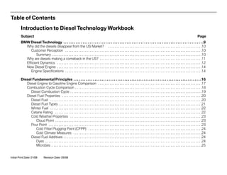
  • 10. Why did the diesels disappear from the US Market? In the US market, diesel vehicles have not had much success over the last 20 years. Most of this is due to customer perception and the relatively low cost of gasoline. Although many people feel that the price of gasoline is high in the US, other parts of the world pay much higher prices due to the additional taxes. In comparison, fuel prices in Europe are twice as high as in the US. This accounts for the difference in the overall acceptance of diesel between the US and European markets. In the early 1980’s the price of gasoline was increasing, but was not enough of a motivating factor to convert customers to diesel vehicles in sufficient numbers. Diesel engines did not offer enough of an alternative to gasoline engines because they did not perform as well. They were sluggish and did not deliver much in the way of dynamic performance. Customer Perception More than 20 years ago, the diesel vehicles available in the US market did not have the advantages of today's technology. By the time BMW brought the 524td to the US, the diesel market had already declined due to the less than desirable aspects of some of the competitive products available at the time. Much of the negative perception of diesel vehicles centered around the odors from the exhaust and fuel itself. Also, diesel exhaust contained a high amount of soot which contributed to the dirty image of diesel vehicles. The combustion process in early diesel engines was abrupt and created a lot of additional engine noise as well. This noise gave the diesel passenger car more of a “truck-like” impression to potential customers. Summary The absence of diesel powered passenger cars in the US can be summed up in the following areas: • Engine noise • Exhaust odors • Dirty, soot emissions excessive • Fuel smell • Low power, lack of performance, sluggish • Cold starting performance • High emissions of NOX The above mentioned issues on the diesel engine have been resolved with the advancements in engine, emissions and fuel injection technology. In the subsequent pages, the latest diesel technology will be reviewed and explained in more detail. 10 Introduction to Diesel Technology Workbook $2.70 $5.37 U.S. Average Price for Diesel Fuel (summer 2007) European Average Price for Diesel Fuel (summer 2007)
  • 11. Why are diesels making a comeback in the US? Given the current global concerns, BMW diesel engines are a logical choice for customers looking for economy and performance. There are other alternatively fueled vehicles on the market today, but BMW offers a true “premium” experience with the diesel engine. Everyday, the news is filled with articles on global warming and the need for a reduction in CO2 emissions. There are continuing discussions on the need to reduce our dependence on foreign oil and to look for alternatives. BMW is offering alternatives in the form of Hydrogen power, future Hybrid technology and now “Diesel Power” for the Ultimate Driving Machine. In the last 20 years, BMW has developed “cutting edge” diesel engines which have gone relatively unnoticed in the US market. This is due, primarily, to the perception of the customer. Past negative experiences or a lack of overall diesel knowledge have kept customers from experiencing diesel technology. The lack of available diesel vehicles in the US has only served to keep interest at a minimum. Today, more and more customers are becoming aware of diesels and the potential benefits of ownership. BMW offers all of these benefits with the addition of performance and the usual value that customers expect. The new BMW engines benefit from the latest “common rail” fuel injection systems. These systems are high pressure, precision injection systems which are capable of having multiple injection events. These systems contribute to the increased performance and reduction of emissions. As compared to the M21 engine from 1983, the latest BMW diesel vehicles have improved in the following areas: • Engine noise has been reduced by engine design and fuel injection strategy. Additional engine soundproofing also contributes to the reduction in noise. • Particulate emissions have also been reduced by 99% as compared to the M21 engine. This was accomplished by injection strategy and by the new diesel particulate filter (DPF). • Fuel consumption has been reduced by 20%. • Torque output has been increased by 160% through the use of the innovative twin-turbocharger design. • Horsepower has been increased by more than 135%. • NOX is further reduced by the diesel oxidation catalyst, EGR valve and by the new SCR system. • Other engine modifications also contribute greatly to the modern BMW diesel engine. In short, it’s time to bring the diesel back. Introduction to Diesel Technology Workbook 11
  • 12. 12 Introduction to Diesel Technology Workbook Efficient Dynamics Today, much of the focus from the automotive industry centers around fuel efficiency and concern for the environment through the reduction in CO2 output. Usually, the words “efficient” and “dynamic” are not usually adjectives used to describe the same vehicle. However, this is not the case when describing vehicles from BMW. Many of our customers are familiar with our most famous tag line “The Ultimate Driving Machine” and they won’t settle for anything less. It is a huge challenge to not only meet performance expecta- tions, but to maintain overall efficiency and environmental responsi- bility. BMW has been able to meet and exceed these goals through the latest innovations in engine technology. Systems such as VANOS, Valvetronic, lightweight engine construction and the latest in engine management have contributed to increasing performance while improving fuel economy. One of the first vehicles to be associated with the “Efficient Dynamics strategy was the BMW Hydrogen 7. This vehicle is also the flagship for BMW’s “Clean Energy” concepts. The new BMW Hydrogen 7-series is “bivalent” which means it can be run on both gasoline and hydrogen. The “Hydrogen 7” has a V-12 internal combustion engine which takes advantage of one of the most plentiful and “eco-friendly” resources on Earth - Hydrogen. Using hydrogen as an automotive fuel is not an entirely new concept for BMW. These ideas have been in development by BMW since the 1970’s. It’s important to note, that the new Hydrogen 7 is not only a concept vehicle, but is a production vehicle which is currently for sale. Although it is not currently available in the US, is being tested here and will be for sale in other markets.
  • 13. BMW’s dedication to Efficient Dynamics does not rest on a single vehicle, but rather is evident on many other new products and technologies. For example, BMW gasoline engines have had many fuel saving innovations for many years. Recently, Valvetronic technology has allowed BMW vehicles to gain “best-in-class” fuel economy across the model line. Some of the other engine innovations include high-precision direct fuel injection for gasoline engines. The HPI system allows the N54 engine to maintain maximum performance and astounding fuel economy in a 300 hp engine. To complement all of the engine technology currently in use, BMW will be adding diesel powered BMW’s to the model line by the end of 2008. Besides the obvious fuel saving advantages of diesel engines, there are many performance related aspects of this new technology. The new 335d for the U.S. market is expected to accelerate from 0-62 mph in 6.2 seconds while achieving a fuel economy of 23/36 mpg (city/highway provisional data). The same engine in the X5 can accelerate to 62 mph in 7.2 seconds while offering fuel econo- my figures of 19/26 mpg (city/highway provisional data). With its carbon emissions down 10% - 20% from comparable gasoline vehicles, and near-elimination of both smoke and NOx emissions, BMW Advanced Diesels will be every bit as clean as CARB-legal gasoline engines when they are introduced in the US in 2008. Both diesel and gasoline engines from BMW have taken home the prestigious “International Engine of the Year Award” several times. Now, one of these award-winning diesel engines will be available in 2009 models. Introduction to Diesel Technology Workbook 13
  • 14. 14 Introduction to Diesel Technology Workbook New Diesel Engine Some of the features on the M57TU2 TOP include: • A horsepower rating of 265 hp • 425 lb-ft (580 Nm) of torque • 3rd Generation common rail fuel injection (1600 bar) with Direct Injection • Piezo-electric injectors • Two-stage turbocharging with intercooler • Lightweight aluminum alloy crankcase • Particulate filter (DPF) • EGR system with EGR cooler • Diesel Oxidation Catalyst • Digital Diesel Electronic (DDE) • Selective Catalytic Reduction (SCR) System In addition to the features listed above, the new 6-cylinder diesel includes fuel heating system and a new “fast start” glow plug system to ensure optimum cold weather starting. Note: In accordance with the current engine numbering system, the M57TU2 TOP engine will be known officially as the M57D30T2. Engine Specifications M57TU2 TOP/M57D30T2 Number of Cylinders 6 Bore 84 Stroke 90 Displacement 2993 cm3 Compression Ratio 16.5:1 Compression pressure > 12 bar Maximum RPM 5250 Maximum continuous RPM 4400
  • 15. Introduction to Diesel Technology Workbook 15 Classroom Exercise - Facts and Figures Discuss the topics listed amongst yourselves. Circle True or False next to the statements below. Your instructor will assist you in your discussions. 1. Diesel fuel costs less to refine from crude oil than gasoline True False 2. Gasoline is more heavily taxed than diesel fuel True False 3. Diesel fuel has more carbon content per gallon than gasoline True False 4. Glow plugs on BMW diesel engines are only used for cold starting True False 5. Diesel fuel is more volatile than gasoline True False 6. Hybrids are more efficient than diesels in all driving situations ( e.g. Highway/City) True False 7. BMW allows the use of bio-diesel fuel (such as B10, B20 etc.) True False 8. Adding gasoline to a diesel fuel tank is acceptable in small amounts True False 9. Diesel engines operate best at Lambda values of 1.0 True False 10. Sulfur provides the necessary lubrication qualities found in diesel fuel True False 11. Diesels produce more untreated NOX that gasoline engines True False 12. The new generation of BMW diesel vehicles will be sold in all 50 states True False
  • 16. 16 Introduction to Diesel Technology Workbook First and foremost, a diesel engine operates on the “compression ignition” principle. A compression ignition engine begins the combustion cycle without the need for an external ignition system. What makes a diesel engine attractive to potential customers is that it is much more efficient than a gasoline engine. This is due to several factors: • Diesel engines run at a much higher compression ratio • The energy density of diesel fuel is much higher than an equivalent amount of gasoline • Overall, diesel engines are more thermally efficient than gasoline engines • Diesel engines are run very lean (with excess air) • Diesel engines operate with the throttle in the open position which reduces pumping losses In order to ignite fuel without a spark, the compression ratio must be relatively high. The compression ratio on most gasoline engines ranges from 8:1 up to as high as 12:1. On the other hand, compression ratios on diesel engines range from 16:1 up to about 22:1 for most passenger car engines. A direct benefit of a higher compression ratio is increased thermal efficiency. In comparison to a gasoline engine of comparable displacement, modern diesel engines generate more cylinder pressure during the compression phase. The average “mean cylinder pressure” value of a turbocharged diesel engine is from 8 to 22 bar, while a comparable turbocharged gasoline engine is only about 11 to 15 bar. A higher mean pressure value in combination with the higher energy density of diesel fuel translates to more pressure during combustion. This higher combustion pressure is responsible for much higher output torque. This additional torque is available at a relatively low RPM as compared to a gasoline engine. The load control of a diesel engine is not carried out by regulating the amount of air as on a gasoline engine. Rather, the diesel engine is “throttled” by the amount of fuel injected. This type of load control means that the throttle butterfly is mostly open during all engine phases. Since the throttle is always open, there is always more than enough oxygen available to burn all of the fuel injected. This allows then engine to operate in a very lean state which also contributes to increased efficiency of the diesel engine. In comparison, gasoline engines must run at a lambda value as close to 1 as possible. A diesel engine can operate at lambda level of 1 to 2 under load and up to 10 when at idle or under low load conditions. An added benefit of having the throttle open during most phases of engine operation is the reduction of pumping losses. This has the same beneficial effect that Valvetronic has on a gasoline engine. In summary, early diesel engine designs were already much more efficient than the prevailing gasoline engine technology. However, fairly recent developments in engine and fuel injection technology have contributed to major advances in the success of the diesel engine. In particular, modern BMW “Performance Diesel” engines provide the added bonus of economy and performance. The already proven diesel engine has been enhanced and optimized to fulfill the brand promise of “The Ultimate Driving Machine”. Diesel Fundamental Principles
  • 17. Introduction to Diesel Technology Workbook 17 Diesel Engine to Gasoline Engine Comparison In order for the diesel engine to start it’s combustion cycle, fuel must be ignited by the heat of compression. The fuel used must be able to spontaneously ignite (without the help of a spark from an external ignition source). So, the fuel required for a diesel engine must have special properties to be compatible with proper engine operation. The best way to illustrate this is to compare both engines and the fuel used. The following is a comparison of a gasoline engine as compared to a diesel engine: Specification Gasoline Engine (Otto) Diesel Engine Ignition Type Spark Ignition Compression Ignition Compression Ratio Between 8:1 and 12:1 Between 16:1 and 22:1 Efficiency 25-30% 36-45% Maximum Engine Speed 7000-8250 RPM up to 5250 RPM Exhaust Temperature (under full load) 700-1200 Degrees Celsius 300-900 Degree Celsius Fuel Type Gasoline (Octane rating = resistance to knock) Diesel (Cetane rating = ability to ignite) Fuel Density 0.74 - 0.77 0.82 - 0.85 Flash Point -47 Degrees Celsius (-52.6 Degrees Fahrenheit) 55 Degrees Celsius (131 Degrees Fahrenheit) Ignition Temperature 550 Degrees Celsius (1022 Degrees Fahrenheit) 350 Degrees Celsius (662 Degrees Fahrenheit)
  • 18. 18 Introduction to Diesel Technology Workbook Much like a gasoline engine, the diesel engine uses the 4-stroke cycle. The familiar sequence of; Intake > Compression > Power and Exhaust is much the same on a diesel engine. The difference is mostly in how the fuel is ignited and when fuel is introduced into the combustion chamber. The other area in which diesel engines differ is in the compression ratio. The typical gasoline engine has compression ratios of between 8:1 up to about 12:1. On the other hand, diesel engines have a typical compression ratio of between 16:1 and 22:1. The higher compression ratio is required to sufficiently compress the air charge and raise the temperature to the ignition point. The illustrations below show the sequence of the combustion cycle on a conventional gasoline engine with “manifold injection”. Intake Stroke Gasoline Engine A low pressure area is created as the piston moves downward in the cylinder bore. As the intake valve opens, a mixture of air and fuel is allowed to enter the cylinder to fill the void created by the low pressure area. Compression Stroke Gasoline Engine As the piston moves up in the cylinder, both valves are closed. The mixture of air and fuel is compressed to a specific ratio. Power Stroke Gasoline Engine The compressed air and fuel mixture is ignited by a spark from the ignition system. The piston is forced down in the cylinder by the expanding gases. This creates the necessary force to drive the crankshaft. Exhaust Stroke Gasoline Engine The exhaust valve opens as the piston moves up in the cylinder which expels the spent gases formed during the combustion process. Note: A gasoline direct injection engine would only induct air during this period. Note: A gasoline direct injection engine would operate the same during this period. Note: A gasoline direct injection engine would inject fuel and ignite it with a spark during this period. Combustion Cycle Comparison Note: A gasoline direct injection engine would only compress air during this period.
  • 19. Introduction to Diesel Technology Workbook 19 Intake Stroke Diesel Engine A low pressure area is created as the piston moves downward in the cylinder bore. As the intake valve opens, air is allowed to enter the cylinder to fill the void created by the low pressure area. Compression Stroke Diesel Engine As the piston moves up in the cylinder, both valves are closed. The air is compressed to a high ratio and therefore heated to a high temperature in preparation for the incoming fuel. Power Stroke Diesel Engine Just before the piston reaches TDC, fuel is injected at high pressure directly into the com- bustion chamber. The fuel spontaneously ignites and pushes the piston down in the cylinder. This creates the necessary force to drive the crankshaft. Exhaust Stroke Diesel Engine The exhaust valve opens as the piston moves up in the cylinder which expels the spent gases formed during the combustion process. Note: The recess in the piston and the design of the intake manifold assist in creating a “swirl effect” for the incoming air. Note: Due to the higher thermal efficiency of a diesel engine, the exhaust temperature is lower as compared to a gasoline engine. Note: Fuel is injected for a longer time during this period. This feature contributes to the additional torque generated by a diesel engine. Note: Only air is compressed during this period. Diesel Combustion Cycle In the example above, the combustion cycle on the gasoline engine was discussed. In contrast, the sequence below outlines the combustion cycle on the diesel engine. This will help in the understanding of the diesel/gasoline engine comparison.
  • 20. 20 Introduction to Diesel Technology Workbook Diesel Fuel Properties Before discussing diesel fuel injection or fuel systems, it is necessary to explain the properties of diesel fuel and how it differs from gasoline. Although both fuels are distilled from crude oil, they each have their own uses and applications and should never be interchanged. Diesel Fuel As with gasoline, diesel fuel is a by-product of the distillation of crude oil. Diesel fuel is a hydrocarbon with different chemical properties than gasoline. Diesel fuel is part of the “middle distillates” derived from crude oil. This means that diesel fuel is “heavier” than gasoline but “lighter” than oil used for lubrication (i.e. motor oil). There are numerous advantages to diesel engines, due to the properties of the fuel used. Some of these advantages include: • Thermal Efficiency - Diesel fuel produces more power than gasoline. In other words, Diesel fuel has a higher energy content. One gallon of gasoline contains about 125,000 BTU of heat energy. In comparison, one gallon of diesel fuel contains about 147,000 BTU. This advantage in thermal efficiency, adds up to increased fuel economy. • Increased Durability - Due to the lubricant properties of diesel fuel, piston ring life is greatly increased. Gasoline has more of a detergent quality which tends to decrease piston ring life. It is not uncommon for light duty diesel passenger vehicles to have an engine which lasts more than 200,000 miles. • Improved Emissions - Diesel fuel contains more carbon atoms per gallon and therefore will emit more CO2 per gallon. However, the increased efficiency of a diesel engine allows for an overall reduction in CO2 (per mile). In comparison, diesel engines are run leaner (with excess air), and produce lower levels of HC, CO and CO2. The lower volatility of diesel fuel, allows for less evaporative emissions overall. The only area where diesel engines do not excel are in NOX and Particulate Matter (PM). But, new technology allows diesel engines to comply with prevailing emission standards. Gasoline Diesel Gasoline The BTU value for gasoline is approximately 125,000 BTU per gallon Diesel Fuel The BTU value for diesel fuel is approximately 147,000 BTU per gallon
  • 21. Introduction to Diesel Technology Workbook 21 Diesel Fuel Types The term “diesel fuel” is a generic term, it refers to any fuel for a compression ignition engine. As mentioned before diesel fuel is derived from the “middle distillates” of crude oil. There are other similar products in this range such as kerosene, jet fuel and home heating oil just to name a few. However, each of these products is designed for a specific application. In theory, these additional products may work in a diesel application, but it is not recommended. Diesel fuel has specific properties which are designed to offer the best reliability, the best fuel economy and the highest compatibility with engine and fuel system components. As far as passenger cars are concerned, there are two main types of diesel fuel. These are Grade 1 and Grade 2. Usually referred to as Diesel Fuel #1 and Diesel Fuel #2. Mostly, Grade 2 is used for passenger cars and is the most widely available. The difference between diesel fuel #1 and #2 is addressed in the following: • Diesel #1 has about 95% of the BTU content as #2 diesel. • Diesel #1 has a lower viscosity and provides less lubrication to the fuel system components such as the fuel pump and injectors. • Diesel #1 has a lower waxing point than #2 and will perform better a low ambient temperatures. • Diesel #1 usually has a slightly lower Cetane rating than #2, but is above the minimum rating of 40. Diesel #2 Diesel #1
  • 22. 22 Introduction to Diesel Technology Workbook Winter Fuel Petroleum companies generally offer “winter” and “summer” grade fuels on a seasonal basis. Winter fuel is created by blending a specific amount of #1 Diesel fuel to a quantity of #2 Diesel fuel. This lowers the freezing (waxing) point to prevent fuel filters from clogging or the fuel from causing any cold weather starting problems. In the heavy trucking industry, there have been some other methods to “winterize” diesel fuel. Some of these methods include adding kerosene or other fuels to improve cold weather starting ability. However, this is not recommended for passenger cars and may, in fact, cause engine or fuel system damage. Therefore, the only recommended method is to purchase diesel fuel from a reputable retailer Cetane Rating When rating gasoline, the term “octane” has been used to refer to the anti-knock quality of a fuel. Octane rating refers to the resistance to prematurely ignite under pressure. When the octane number is higher, the fuel is more resistant to pre-ignition and therefore engine knock. Therefore, a higher octane number is more desirable. For example, today’s octane ratings range from 87 to 93 for commercially available passenger cars. In Diesel applications, the term “cetane” is used to rate fuel quality. However, the desired fuel quality goals are different for diesel. The cetane rating of diesel fuel refers rather to the “ease of ignition”. After all, a diesel engine is a “compression ignition” engine and therefore, it is more important for diesel fuel to combust easily under pressure. Cetane ratings are in in a range of 0 to 100. 100 is an indicator of pure Cetane (n-hexadecane), or the most combustible. Most commercially available diesel fuel has a cetane rating of about 45. A rating of 40 is usually considered to be the absolute minimum rating for today’s passenger vehicles. Newer BMW vehicles will require a Cetane rating of 51. Always check the owner’s manual to see the minimum fuel requirements and the recommended cetane number. A higher cetane rating also contributes to better starting especially in cold weather. When possible, it is always better to use fuel with a higher cetane rating. Also, a higher cetane number equates to a reduction in NOX and particulate matter emissions. Octane 92 Cetane 51
  • 23. Cold Weather Properties As with all fuels distilled from crude oil, there is a presence of paraf- fin wax. This wax content depends of the type of fuel. Since diesel fuel is a “middle distillate” of crude oil, there are more paraffin compounds present. These waxy compounds flow well at normal ambient temperatures. However, in cold operating temperatures, these compounds begin to solidify and can restrict fuel flow resulting in difficult starting. Cloud Point The cloud point is the temperature at which the fuel will start to solidify. The paraffin compounds begin to crystallize and the fuel becomes cloudy. The ability of the fuel to flow is impeded, but is still able to move through the system. The cloud point of #2 Diesel fuel is about 20 degrees Fahrenheit ( -7 degrees C). Pour Point Pour point is the temperature in which the fuel will no longer flow. It is usually 6 to 10 degrees Fahrenheit below the cloud point. Introduction to Diesel Technology Workbook 23 Temp = 100° F Temp = 20° F CLOUDY CLEAR Temp = 100° F Temp = 30° F
  • 24. Cold Filter Plugging Point (CFPP) Diesel fuel is a hydrocarbon which contains paraffin waxes. At warm temperatures, these waxes will flow easily through the fuel system. However, at low ambient temperatures, these waxes will tend to solidify. This situation causes the fuel to start to solidify. Due to the paraffin content in middle distillate's like diesel fuel, is is possible during cold temperatures for the fuel to solidify. The CFPP is about -4 degrees F ( -20 degrees C). Cold Climate Measures Most, if not all, modern vehicles equipped with diesel engines employ measures to heat the fuel and reduce the possibility of wax formation a.k.a gel. The measures include a heated fuel filter and glow plugs. These systems will be discussed in subsequent train- ing modules. Diesel Fuel Additives When diesel fuel is refined, numerous additives are used to improve the qualities of the fuel. These additives can be intro- duced at the refinery level or at the distribution level. One such additive is an “Anti-foaming” agent which helps when refueling the vehicle by reducing the foam buildup when the fuel is aerated. Detergents are added to allow the diesel fuel to assist in the clean- ing of engine and fuel system components. These detergent com- bat the possibility of sediment or “gum” buildup which can be detrimental to the fuel system. Modern high pressure diesel fuel injection systems are sensitive to any dirt or varnish buildup. California requires the use of low aromatic diesel fuel. Additives are used in this case to lower the aromatic quality of the fuel. In the future, some other states may require the use of “low aromatic” diesel fuel. Some additional additives include: • Cetane number improvers • Smoke suppressants • Low temperature operability additives • Biocides (to prevent growth of microbes in the fuel) • Corrosion inhibitors • Dyes (for identification) • Lubricity additives Dyes Dyes are added to diesel fuel for identification. There are two pri- mary reasons that fuel needs to be identified. The IRS requires diesel fuel to be identified for tax purposes and the EPA requires fuel to be identified for fuel quality (i.e sulfur content). To comply with the tax code, fuel is usually dyed red for agricultural use. The fuel used for farm equipment is not as heavily taxed as that which is used for “over-the-road vehicles. Using “red-diesel” in a passenger car or truck is a violation of the tax code and there- fore should not be used. The so-called “red diesel” fuel is also dyed to show visible evi- dence of “high-sulfur”fuel. 24 Introduction to Diesel Technology Workbook Fuel “IN” FLOW Fuel “OUT”
  • 25. Starting in 2007, the diesel fuel used in new cars is supposed to be “ULSD” or Ultra-low Sulfur Diesel. The EPA requires a specific quantity of red dye to be used in any fuel which is not of the ULSD variety. The sulfur content of this fuel has been drastically reduced to help modern vehicles meet emission requirements. Therefore, “red diesel” should not be used in any “over-the-road” vehicle. Microbes When fuel is refined, the high temperatures achieved during this process will “sterilize” the fuel. However, after the fuel has cooled, it is possible for microorganisms to grow. This is possible because there is usually some water present is diesel fuel which comes from condensation and during the trans- fer/distribution phases. The microbes feed on the interface between the water and fuel. These colonies can thrive in the absence of light. Some microbes are also anaerobic, which means they can survive in the absence of oxygen as well. These microbes can multiply into colonies which can become large enough to clog fuel system components. The best way to combat these organisms is to keep the fuel as clean as possible and reduce or eliminate the presence of water. Diesel fuel distributors use biocides to attack the microbes and reduce their numbers. Sulfur Content Sulfur is a naturally occurring element found in crude oil. Through the refining process various sulfur compounds occur and are pres- ent in the final product. Up until 1985, not much attention was paid to the sulfur content in diesel fuel. The presence of sulfur in diesel fuel contributes to unwanted soot and particulate emissions which are present is diesel exhaust. So, beginning in 1985, the EPA and CARB began with regulations on the sulfur content of diesel fuel. This led to the use of low sulfur diesel fuel. Up until 2007, diesel fuel regulations required the use of “Low Sulfur Diesel” or LSD. The sulfur content of LSD is 500 parts per million. LSD fuel was compatible with the diesel technology at that time, but there was still substantial particulate matter emissions (PM). For the 2007 model year, the EPA has mandated the use of Ultra Low Sulfur Diesel fuel or ULSD. This new fuel represents a 97% decrease in sulfur content. The maximum sulfur content in ULSD is 15 ppm. As a comparison, this amounts to about 1 ounce of sulfur for an entire tanker truck of diesel fuel. One of the reason that ULSD fuel is needed is to be compatible with the latest generation of “clean diesel” vehicles. These vehi- cles include a Diesel Particle Filter (DPF) which is used in the exhaust system to trap and reduce particulate emissions. The use of ULSD assists greatly in the reduction of particulate matter emis- sion. Using LSD fuel in a vehicle which requires ULSD can damage the DPF and result in unwanted emission levels and unnecessary com- ponent damage. So, only ULSD fuel should be used especially on vehicles equipped with a DPF. Introduction to Diesel Technology Workbook 25
  • 26. When refueling a vehicle which requires ULSD, be sure to check the label located on the pump. This label should be in a conspicu- ous location. Above, is an example of the correct label for ULSD fuel on the left. The right is an example of LSD fuel (pre-2007). By December of 2010, all gas stations are required to be in compli- ance with the ULSD requirements. As of 12/10, LSD fuel will no longer be available for highway use. Vehicles which require LSD will be able to run on ULSD without any modifications. The ULSD fuel meets all lubricity requirements for vehicles made prior to 2007. Lubricity One of the qualities of diesel fuel is that is provides the needed lubrication for engine and fuel system components. By nature, diesel fuel is very oily and is more viscous (thicker) than gasoline. This is why diesel fuel is sometimes referred to as fuel oil. Some components such as the injectors and high pressure pump will not function properly without lubrication. The presence of sulfur and sulfur compounds contribute to the overall lubrication qualities of the fuel. With LSD fuel and the new ULSD, additives are used to enhance the lubricity of the fuel. So, older vehicles will be able to ULSD without any modifications or concerns. Grades ULSD fuel will be available for both Diesel #1 and Diesel #2 grades. Off Road Use Currently, ULSD is not required for “off-highway” use. This includes agricultural equipment, locomotive and marine use. ULSD will not be required on these applications until 2010. Until that time, LSD fuel with 500 ppm sulfur will be available (see label below). 26 Introduction to Diesel Technology Workbook
  • 27. Flash Point and Auto-ignition The flash point of a fuel represents the lowest temperature as to which it will be able to be ignited. Gasoline and diesel fuel have different properties, and therefore different flash points. A gasoline engine or “spark ignition” engine needs a fuel which can be ignited by a spark, but will not “self-ignite” under the heat of compression. Gasoline which has a lower flash point that diesel fuel can be ignited easier with a outside source of ignition i.e. spark or open flame. The flash point of gasoline is at about -43 degrees Celsius (-45 F) which works well in a gasoline engine, but not in a diesel. A low flash point also makes gasoline more dangerous to handle. Gasoline, however, has a higher auto-ignition temperature which helps the fuel resist self ignition in a gasoline engine. The auto- ignition temperature of gasoline is about 256 degrees C or 475 degrees Fahrenheit. Diesel fuel has a much higher flash point of about 52 degrees C or above. This flash point varies between fuel types i.e. #1 or #2 diesel. In contrast, the auto-ignition temperature of diesel fuel is 210 degrees C or 410 degrees Fahrenheit. This particular quality of diesel fuel is compatible with a “compression ignition” engine. Fuel Mixing Among the other attributes of automotive fuels, flash point and auto-ignition temperature are perhaps the primary reasons why these fuels should never be mixed. Mixing gasoline into diesel fuel will lower the flash point rendering the fuel unsafe to handle. Also, the flash point and auto-ignition temperature of gasoline would adversely affect a diesel engine, even to the extent of engine dam- age. With regards to a diesel engine, it is also important to be aware that gasoline has little in the way of lubrication properties sufficient for diesel fuel system components. This is of a particular concern to the high pressure fuel pump which can be damaged when gasoline is introduced into the fuel system. The inverse is also true when fueling a gasoline powered vehicle incorrectly with diesel fuel. Irreparable engine damage can result costing thousands of dollars. Introduction to Diesel Technology Workbook 27
  • 28. Diesel Oil In addition to the fuel used to run a diesel engine, there are also considerations which must be taken into account regarding the lubricating oil in a diesel engine. Since the combustion chamber temperature of a diesel engine is higher than a gasoline engine, the oil temperature is also higher. So, engine oils used in diesel engines must be able to withstand the higher temperature demand. In addition to the already high service demand on diesel engine oil, BMW diesel engines are turbocharged which further increases the demands on the engine oil. In the U.S., lubricating oils are rated through the American Petroleum Institute (API). Engines, whether gasoline or diesel pow- ered, each have their own classification as far as lubricating oils are concerned. The lubricating oil used in current diesel engines must conform with regulations regarding sulfur content. For the correct motor oil for diesel engines, always refer to the proper owner’s manual or the “Operating Fluids Specifications Manual” which can be found in BMW TIS. 28 Introduction to Diesel Technology Workbook
  • 29. Introduction to Diesel Technology Workbook 29 NOTES PAGE
  • 30. 30 Introduction to Diesel Technology Workbook Workshop Exercise - Diesel Engine Fundamentals You will notice that your classroom is set up with various “Information Stations”. The following workshop exercises pertain to these stations. Proceed to the station which pertains to the topics listed below. Information Station 1 (Mechanical): Compare the two pistons, note the differences and answer the following questions. 1. As compared to the piston on the gasoline engine, the diesel piston is: (Circle all that apply) Heavier Lighter Larger Smaller 2. In the following exercise, circle the TRUE statements regarding the pistons on a diesel engine: (Cross out false statements) A. The first piston ring land on a diesel engine is relatively close to the piston crown B. The piston skirt on a diesel engine is deeper than the skirt on a gasoline engine C. On a diesel engine, the piston pin is tapered for weight savings D. The piston pin has a bushing in the connecting rod, but not in the piston (TOP engine). E. The diesel piston contains a major portion of the combustion chamber F. The diesel piston is made from cast iron to withstand high temperatures Compare the two connecting rods, note the differences and answer the following questions. 3. Circle the TRUE statements regarding the connecting rods on a diesel engine: A. The diesel connecting rod has a bushing in the “small end” B. The “small end” of the diesel connecting rod is tapered for weight reduction C. The big end of the connecting rod uses dowel pins for alignment D. The diesel connecting rod is made from forged steel E. The diesel connecting rod is lighter than a connecting rod on a gasoline engine
  • 31. Introduction to Diesel Technology Workbook 31 Workshop Exercise - Diesel Engine Fundamentals Examine the connecting rod bearings and answer the following questions: 4. Circle the TRUE statements regarding connecting rod bearings on a diesel engine: A. The sputter bearing is comprised of 3 layers B. The sputter bearing should be installed in the connecting rod bearing cap C. The sputter bearing has a soft layer to absorb dirt particles D. The sputter bearing is marked with an “S” on the back of the bearing shell Examine the crankcase information and answer the following question: 5. Circle the TRUE statements regarding crankcase on a diesel engine: A. The diesel crankcase has an “open deck” design B. The diesel crankcase uses a “bedplate” for added rigidity in the bottom end C. The diesel crankcase is made from aluminum and has cast iron cylinder liners D. The main bearing caps on a diesel engine are located using dowel pins for precise alignment Examine the cylinder head and valvetrain components and answer the following question: 6. Circle the TRUE statements regarding cylinder head and valetrain components on a diesel engine: A. The intake and exhaust valves on a diesel engine are all the same diameter B. The major portion of the combustion chamber is located in the cylinder head C. The exhaust valves are sodium filled on a diesel engine D. The camshafts are manufactured from cast iron on a diesel engine E. The exhaust camshaft is driven via a gear-to-gear connection with the intake camshaft
  • 32. 32 Introduction to Diesel Technology Workbook Workshop Exercise - Diesel Engine Fundamentals Information Station 2 (Fuel System): Examine the fuel system components and use the poster to determine fuel system operation. Answer the following questions: 1. Which of the following methods is used to drive the high pressure pump on the M57TU2 TOP? (Circle the correct answer) A. Via a direct connection to the exhaust camshaft B. Via a sprocket connection to the timing chain C. Via a lobe on the intake camshaft D. Via a tandem to the vacuum pump 2. Which of the following statements is NOT true regarding the low pressure fuel system on the diesel engine (M57)? (Circle the correct answer) A. The fuel filter is heated to assist in cold starting B. The EKP module controls the fuel pump based only on load-based “demand” information from the DDE C. The low pressure fuel pump is located in the fuel tank D. The EKP module is connected to the PT-CAN 3. Which of the following statements is NOT true regarding the common rail system? (Circle the correct answer) A. The high pressure pump is a 3-piston radial type pump B. The fuel injectors are “piezo-electric”. C. The injectors are identical in operation to those on the N54 (gasoline) engine D. The high pressure fuel pump is lubricated by pressurized engine oil E. Fuel pressure on the common rail system is 200 bar
  • 33. Introduction to Diesel Technology Workbook 33 Workshop Exercise - Diesel Engine Fundamentals Information Station 2 (Fuel System): 4. Review the statements (A-L) below and circle all of the TRUE statements regarding the the properties of diesel fuel? (Circle the correct answer) A. Diesel fuel has more “carbon content” than gasoline B. Diesel fuel #1 is more commonly used in moderate climates C. The Cetane rating of diesel fuel refers to the ease of ignition D. Diesel fuel and gasoline can be mixed in small amounts without any concerns E. Diesel fuel is more volatile than gasoline F. Diesel fuel contains more sulfur than gasoline G. ULSD diesel fuel contains less than 15 ppm of sulfur H. Diesel fuel (when combusted) will emit more CO2 per mile than gasoline I. Bio-diesel fuel is currently not approved for use in BMW diesel vehicles J. BMW diesel engines will only run of diesel fuel which has a Cetane rating of 80 or higher K. Diesel fuel evaporates at a higher rate than gasoline L. Diesel fuel is less expensive to refine than gasoline
  • 34. 34 Introduction to Diesel Technology Workbook Workshop Exercise - Diesel Engine Fundamentals Information Station 3 (Combustion Process): Using the diesel demonstrator, place a small piece of cotton in the tube and press down rapidly on plunger. Take note to see if any combustion takes place. 1. Did combustion take place? (why or why not?) Try spreading the cotton apart and re-try. 2. Did combustion takes place this time? 3. Based on your results, how does the presence (or lack of) oxygen affect combustion? 4. How does the shape and size of the cotton affect combustion? How does this relate to actual combustion in a diesel engine? 5. Which of the following statements are NOT true regarding the diesel combustion process? A. The fuel mixture on a diesel engine is formed externally B. Diesel engines operate most efficiently at a Lambda value of less than 1 C. The fuel mixture on diesel engines is considered to be “homogeneous” D. Fuel is injected into a diesel engine just before the end of the compression stroke
  • 35. Introduction to Diesel Technology Workbook 35 Workshop Exercise - Diesel Engine Fundamentals Information Station 4 (Air Management): 1. Which of the following statement is NOT true regarding the throttle valve on a diesel engine? A. BMW diesel engines do not have a throttle valve B. The throttle on BMW diesel engines is used to control engine load C. The throttle is used to control shudder on engine shut down D. The throttle is used to prevent engine over-rev from excessive oil consumption 2. The swirl flaps on the M57 engine are closed: (Circle the correct answer) A. All of the time B. Only at low RPM/load conditions C. Only at high RPM/load conditions D. Only during engine shutdown E. to reduce engine noise 3. The swirl flaps are located: A. In the exhaust system B. In the intake manifold C. In the air filter housing D. In the cylinder head E. In the throttle housing
  • 36. 36 Introduction to Diesel Technology Workbook Workshop Exercise - Diesel Engine Fundamentals Information Station 5 (Auxiliary Systems): 1. Circle all TRUE statements regarding glow plugs: (Circle all that apply) A. Glowplugs provide heat in the combustion chamber at low ambient temperatures B. Glow plugs are not activated during engine operation (engine running) C. Glow plugs reduce engine noise D. Glow plugs contribute to a reduction in exhaust emissions E. Glow plugs must be changed every 20,000 miles F. Modern BMW glow plug circuits are wired in series G. Glow plug circuits are individually diagnoseable 2. Fast start glowplugs: (Circle all correct statements) A. Operate on a PWM control circuit B. Operate on a high voltage (12 volts) C. Operate on a low voltage (5.3 to 7.8 volts) D. Have low internal resistance E. Have high internal resistance 3. The vacuum controlled motor mounts are actuated (supplied with vacuum): (Circle all correct statements) A. Above 900 RPM B. Below 60 km/h C. At idle D. All the time
  • 37. Introduction to Diesel Technology Workbook 37 Workshop Exercise - Diesel Engine Fundamentals Information Station 6 (Emission Controls): 1. The DPF controls the output of: A. HC B. CO C. PM (soot) D. NOx E. CO2 2. Which of the following exhaust gas constituents is of most concern on a diesel engine? A. HC B. CO C. PM D. NOx 3. Which of the following sensors is NOT used on a diesel engine management system? A. Exhaust gas temperature sensor B. Exhaust gas pressure sensor C. Post-catalyst oxygen sensor D. Air charge temperature sensor
  • 38. 38 Introduction to Diesel Technology Workbook Workshop Exercise - Diesel Engine Fundamentals Information Station 6 (Emission Controls): 4. Which two components are installed in the same housing on current BMW diesel vehicles? A. DOC and DPF B. SCR and DOC C. DPF and SCR D. EGR and DOC E. DPF and EGR 5. The SCR system uses a urea compound which breaks down into ___________ when entering the SCR catalyst? A. NH3 B. NO C. O2 D. CO2 E. N2 6. Which of the following components is used to monitor EGR performance (flow)? A. Exhaust gas temperature sensor B. Exhaust gas temperature sensor C. Air charge temperature sensor D. Hot-film air mass meter E. Air charge pressure sensor
  • 39. Introduction to Diesel Technology Workbook 39 Workshop Exercise - Diesel Engine Fundamentals Information Station 6 (Emission Controls): 7. Which of the following will occur in order to initiate DPF regeneration? A. Pre-injection events B. Post injection events C. The throttle is held wide-open D. The swirl flaps are closed 8. Swirl flaps are used to lower NOX: A. At high RPM B. At low RPM C. On deceleration D. Swirl flaps do not influence NOX 9. At idle, diesel engine operate at a Lambda value of: A. .85 B. 1.0 C. 1.15 D. Over 2.0
  • 40. 40 Introduction to Diesel Technology Workbook In the early stages of diesel engine development, most if not all were used in stationary applications for power generation, pump- ing or to provide motive power for large ships. The engines were heavy and impractical for use in ground transportation. During the early part of the 20th century, diesels were gradually downsized and improved to make mobile applications possible. Although diesel engines were always more mechanically and thermally efficient than gasoline engines, the early designs were heavy and took up a lot of space. So, much of the early develop- ment of “mobile” diesel engines centered around heavy trucks. By the time diesel engines were adapted to automobiles in the 1930’s, the engine size was reduced and lightened considerably. But, this weight reduction was still not enough to make the diesel engine a great performer. Most of the early automotive diesel engines were using cast iron cylinder blocks and cylinder heads. The fuel efficiency that was gained from the use of diesel engines was somewhat offset by the heavier engine designs. As a result, performance suffered and the overall opinion of diesel engines was that they were slow and sluggish. BMW did not start to develop a diesel engine until the late 1970’s when fuel prices were on the incline and the environment was becoming a concern. The sluggish performance of early diesel engines did not fit into the “sporty” driving style of BMW cus- tomers. Over the years, other vehicle manufacturers designed diesel engines and marketed diesel powered vehicles, but most were not considered sporty or high-performance in any way. Therefore, BMW needed to develop a diesel engine that was a “real” alternative to the gasoline engine. Anything less would not fit into the image of the “Ultimate Driving Machine”. The development of the M21 engine was preceded by an experi- mental diesel engine known internally as the M105 which was ini- tially developed in 1978. The production version of the first BMW diesel engine (M21) would be introduced in 1983. Early BMW diesel engines utilized cast iron for crankcase construction. This was due to to the high combustion chamber pressures generated in the diesel combustion cycle. The latest diesel engines from BMW take advantage of advance- ments in aluminum casting technology. This allows the current and future diesel engines to be lighter without compromising strength. Some of the other areas which are different in diesel engines extend to many of the internal engine components. These areas include pistons, crankshaft, connecting rods, cylinder head and valvetrain. These components are generally stronger and are constructed of different materials as compared to their counterparts on gasoline engines. Engine Mechanical
  • 41. Introduction to Diesel Technology Workbook 41 Engine Construction Comparison In order to be compatible with the higher combustion pressures and torque output in a diesel engine, the crankcase must be stronger and more robust than a gasoline engine. Early BMW diesel engines used a cast iron crankcase, but current advances in aluminum casting technology have allowed the use of lightweight alloy cylinder blocks for diesel applications. The new M57 aluminum crankcase saves 20 kg over the cast iron version. One of the first engines to use this technology was the M57TU2 (6-cylinder) and later the M67TU (8-cylinder). Both of these engines were introduced for the 2005 model year (in non-US markets). The aluminum crankcase has externally cast ribs in addition to stronger aluminum alloy to ensure optimum block rigidity. The graphics shown below are an illustration of the differences between the crankcase on a diesel engine as compared to a crankcase used on a gasoline engine. Note the additional cast ribs on the diesel crankcase which contributes to the needed rigidity. Block rigidity is further optimized by the closed deck design as compared to the open deck on the N54/N52 engine. Crankcase for diesel engine (M57TU2 aluminum) Crankcase for gasoline engine (N54 aluminum)
  • 42. 42 Introduction to Diesel Technology Workbook Piston, diesel engine - typical Piston, gasoline engine - typical Piston - Gasoline Engine This gasoline piston above reflects the type used on a conventional gasoline engine. The piston skirt as compared to the diesel piston is quite thin. The design goals on a gasoline piston include making a strong but lightweight unit which is also “friction optimized”. The valve reliefs are more pronounced to accommodate additional valve lift. The piston pin is smaller and tapered to save weight without compromising strength. Piston - Diesel Engine As can be seen from the above graphic, the diesel piston is more robust. The piston crown and skirt are noticeably thicker. As far as material is concerned, a stronger aluminum alloy is used. The area between the piston crown and the first ring land (fire land) is much larger than that used on a gasoline engine. The piston crown itself is unique and features minimal valve reliefs and a large recess. This recess is used to accommodate the injec- tor spray pattern and assist in mixture formation. The piston pin is also larger and features a bushing in the piston pin boss. An oil cooling passage in the piston allows for a jet of pressurized oil to completely encompass the underside of the piston to keep it piston crown cool. The increases piston and ring life while helping to lower NOX. Pistons, Crankshaft and Connecting Rods One of the major differences between gasoline and diesel engines is in the pistons. The pistons on a diesel engine are subjected to very high pressures and therefore must be considerably stronger. On the diesel piston, a portion of the combustion chamber is in the crown.
  • 43. Introduction to Diesel Technology Workbook 43 In order to contain the additional forces generated in the diesel combustion cycle, the crankshaft is made from forged steel, cast iron crankshafts are not used. In some cases, the crankshaft journal diameters are slightly larger as well. This is dependent upon the engine version. The connecting rods must also be stronger to accommodate the additional forces from the combustion process. To accomplish this, the rods made from forged steel and are significantly thicker in the beam area and have a larger piston pin.
  • 44. 44 Introduction to Diesel Technology Workbook Cylinder Head and Valvetrain The cylinder head on a diesel engine differs in several ways as compared to a cylinder head on a gasoline engine. Obviously there are no accommodations for spark plugs, but rather glow plugs are centrally located in the combustion chamber. The fuel injector is also located centrally in the combustion chamber adjacent to the glow plug. The angle of the valves on a BMW diesel engine are also slightly different as compared to a gasoline engine. Gasoline engines depend upon the optimization of intake air flow to meet volumetric efficiency requirements. So, BMW gasoline engines depend upon the design of the intake and cylinder head to achieve these goals. On the other hand, diesel engines are already efficient in this area due to the fact that the throttle is open most of the time. This reduces pumping losses and improves air flow with out the use of special designs. When comparing the cross-sectional views of the two cylinder heads below, notice the angle of the valves. The gasoline engines utilizes a more extreme angle between the intake and exhaust valves to improve flow and help form the shape of the combustion chamber. The diesel engine has a valve layout that is much less extreme and the combustion chamber is relatively non-existent. Index Explanation A 2-Valve arrangement (i.e. M21) B 4-valve arrangement (i.e. M57) 1 Combustion chamber (surface/ceiling) 2 Valves 3 Injection port (swirl chamber/glow plug integrated) 4 Glow plug 5 Injector (direct injection) Cylinder head cross section Gasoline Engine Cylinder head cross section Diesel Engine
  • 45. It is also important to note that the intake and exhaust valves on gasoline engines are of different sizes, with the intake valves being larger than the exhaust valves. The N54 engine, for example, has intake valves which are 31.5 mm and exhaust valves of 28 mm diameter. Some of the earlier diesel engines have had valves which are the same size. The M57TU1 TOP , which is not a US version engine, has a valve diameter of 25.9 mm for all valves, both intake and exhaust. However, the M57TU2 TOP (M57D30T2) uses only a slightly larger intake valve of 27.4 millimeters. Camshafts The camshafts on the M57 are a composite design for weight savings. This process is referred to as the “Presta” process which uses a steel tube for the camshaft. The tube is rolled to create a “knurled” area around it’s circumference. The lobes have splines which interfere with the knurling on the camshaft tube. The lobes are pressed on and locked to the camshaft in the specified positions. This process provides strength with a considerable reduction in weight. Introduction to Diesel Technology Workbook 45 Index Explanation 1 Intake valves (27.4 mm) 2 Injector (direct injection) 3 Glow plug 4 Exhaust valves (25.9 mm) Index Explanation 1 Camshaft lobe 2 Roller for Presta process 3 Camshaft (steel tube) 4 Camshaft lobe (locked on to steel tube) 5 “Knurling” on camshaft 6 Internal splines on camshaft lobe
  • 46. Lubrication System The oil circuit serves the purpose of supplying with oil all points in the engine requiring lubrication and cooling. As with all BMW engines, the diesel engine is equipped with a forced feed lubrication system. The oil drawn in by the oil pump from the oil pan via an intake pipe flows through the full-flow oil filter and then passes into the main oil gallery or channel which normally runs parallel to the crankshaft in the engine block. Branch galleries lead to the main bearings of the crankshaft. The crankshaft has corresponding holes to feed oil from the main bearings to the crankpins and connecting rod journals. Part of the oil is branched off from the main oil gallery and fed to the corresponding lubrication points in the cylinder head. The following system overview uses the M57 engine as an example to demonstrate the general layout of the oil circuit. 46 Introduction to Diesel Technology Workbook Index Explanation 1 Camshaft bearing 2 HVA 3 Oil dipstick 4 Oil filter 5 Chain tensioner 6 Main oil gallery 7 Oil supply, exhaust turbocharger 8 Unfiltered oil gallery 9 Oil pump 10 Oil pan 11 Intake pipe with screen 12 Channel for oil spray nozzles 13 Crankshaft bearing 14 Oil spray nozzle
  • 47. Introduction to Diesel Technology Workbook 47 From Oil Pan to Oil Pump The oil pump (3) draws in oil from the oil pan (6) via the intake pipe with oil screen (5). The intake pipe is positioned such that the intake opening is above the oil level (4) under all operating conditions. An oil screen is integrated in the intake pipe in order to keep coarse dirt particles away from the oil pump. Index Explanation 1 Oil filter 2 Unfiltered oil gallery 3 Oil pump 4 Oil level 5 Intake pipe with oil screen 6 Oil pan
  • 48. Oil Pump Different types of oil pump are used on BMW engines. On the cur- rent diesel engines, a rotor type pump is used. Functional Principle The oil is drawn in by the rotor oil pump and delivered to the pres- sure side. The oil flows via the oil gallery (6) to the oil filter and then into the main oil gallery. The oil flows back into the oil pump hous- ing via a filtered oil gallery (5) where it is used, for example, to sup- ply the oil spray nozzles for piston cooling. The control chamber of the pressure relief valve is connected to this filtered oil gallery (5) by means of a hole (4). Consequently, the system pressure in the oil circuit is also applied in the control chamber. The control piston (2) which is actuated by compression spring (1) forms the limit on one side of the control chamber. The spring force of the compression spring (1) determines the opening pres- sure of the pressure relief valve. The control piston (2) is moved against the spring force when the system pressure in the oil circuit, i.e. also in the control chamber, increases. The special shape of the control piston (2) opens up a connection from the pressure side of the rotor oil pump to the intake. 48 Introduction to Diesel Technology Workbook Index Explanation 1 Compression spring 2 Control piston 3 Oil intake 4 Hole 5 Filtered oil gallery 6 Oil gallery to oil filter Index Explanation 1 External gearwheel 2 Pressurized oil 3 Pressure chamber 4 Internal gearwheel 5 Driveshaft 6 Intake chamber 7 Oil intake M57 Oil Pump - Pressure relief valve closed
  • 49. The oil circuit is short-circuited. Determined by the pressure con- ditions, a certain quantity of oil consequently flows off from the pressure side into the intake. The greater the control piston (2) is opened, the greater the amount of oil that flows off so that the system pressure drops. Since the control piston (2) is opened by the system pressure, equilibrium is established. In this way, a required maximum pres- sure in the system is now exceeded as it is determined by the force of the compression spring (1). There are two reasons for applying oil pressure to the pressure relief valve downstream of the oil filter: • The oil pressure actually in the system is applied and not the pressure between the oil pump and oil filter. If the oil filter were soiled, this pressure would be higher and the pressure relief valve would open before the maximum pressure were reached in the system. • The oil is calmed in the oil filter. Consequently, the pressure relief valve is not subjected to pressure peaks thus enabling more exact valve operation. Pressure Relief Valve The pressure relief valve protects against excessively high oil pres- sure, e.g. when starting the engine with the oil cold. In turn this function protects the oil pump, oil pump drive, oil filter and oil cool- er. The pressure relief valve is installed on the delivery side between the oil pump and oil filter. The pressure relief valve is arranged as close as possible downstream of the oil pump, often directly in the oil pump housing. The opening and control pressure depends on the respective type of engine and is between 3 bar and 5. Specifically, the control pressure on the M57TU2 is 4.0 bar. Introduction to Diesel Technology Workbook 49 Index Explanation 1 Compression spring 2 Control piston 3 Oil intake 4 Hole 5 Filtered oil gallery 6 Oil gallery to oil filter M57 Oil Pump - Pressure relief valve open
  • 50. Oil Filtering The purpose of the oil filter is to clean the oil and to prevent dirt particles from entering the oil circuit. BMW diesel engines use the full-flow oil filter which allows the entire volume of oil conveyed by the oil pump to pass through the filter before it is fed to the lubrica- tion points. From the oil pump, the oil is fed into the oil filter module and then to the cooling system corresponding to requirement and version. The oil filter module contains valves that fulfill various tasks, which include draining facility for filter change, filter bypass in the case of clogging and preventing the oil galleries running empty. The oil filter cover (2) is connected to the oil filter housing (3) by means of a long threaded stud. When the oil filter cover (2) is removed, the threaded stud releases an oil drain opening (6), via which the oil filter housing (3) can be emptied. Note: The seals for the threaded connection of the oil filter cover must always be replaced as part of the oil serv- ice procedure. The seals are supplied together with the genuine oil filter. The screw connection for the oil filter cover must be tightened to a specified torque, which is defined in TIS. Non-return Valve The oil pump pumps the oil into the oil filter (10). A non-return valve (5) prevents the oil filter (10) draining empty when the engine is not running. This function ensures the lubrication points are supplied with oil for engine start. The oil must overcome an open- ing pressure in the non-return valve (5) of 0.2 bar. Drained oil gal- leries can cause noise or even poor engine performance shortly after starting an engine that has been stationary for a longer period of time. Filter Bypass Valve The system features a filter bypass valve (11) for the purpose of maintaining the oil supply to the lubrication points even when the oil filter (10) is soiled. If the oil pressure increases because the oil filter (10) is clogged, the filter bypass valve (11) will open at an overpressure of 2.5 bar and the oil will flow (unfiltered) to the lubrication points. Heat Exchanger Bypass Valve The heat exchanger bypass valve (8) has the same function as the filter bypass valve (1). If the oil pressure increases because the oil- to-coolant heat exchanger (9) is clogged, the heat exchanger bypass valve (8) will open at a pressure of 2.3 bar, allowing the lubricating oil (not cooled) to flow to the lubrication points. 50 Introduction to Diesel Technology Workbook Index Explanation Index Explanation 1 Filter bypass valve 7 Oil pressure switch 2 Oil filter cover 8 Heat exchanger bypass valve 3 Oil filter housing 9 Oil-to-coolant heat exchanger 4 Oil flow 10 Oil filter 5 Non-return valve 11 Oil flow via filter bypass valve 6 Oil drain opening
  • 51. Engine Oil Cooling There is a risk on high-performance engines and engines subject to high thermal loads that the lubricating oil becomes too hot during vehicle operation. In this case, the viscosity decreases - the oil looses its lubricity and oil consumption increases. This results in deposits in the combustion chamber. The oil film can break down causing bearing and piston damage. These prob- lems can be avoided by the use of an engine oil cooler. These additional coolers are used if the thermal losses can no longer be dissipated over the surface of the oil pan or housing so that the permitted oil temperatures would be exceeded. Oil-to-air or oil-to-coolant heat exchangers are used for the purpose of cool- ing the oil. Oil-to-air Heat Exchanger A conventional engine oil cooler is designed as an oil-to-air heat exchanger. This means the heat is given off from the oil to the ambient air with no further medium involved. The design of such an engine oil cooler is comparable to that of a coolant radiator. The oil flows through the engine oil cooler with its large surface area facilitating effective heat dissipation. Oil-to-coolant Heat Exchanger Oil-to-coolant heat exchangers are used in the engine oil and trans- mission fluid heat management system. They ensure the oil heats up rapidly while sufficiently cooling the oil. Engine oil and coolant counterflows through the oil-to-coolant heat exchanger on several planes, thus transferring heat from one fluid to the other. Oil Spray Nozzles Oil spray nozzles are used to feed oil for lubrication or cooling pur- poses to defined positions of moving parts that cannot be reached via oil galleries. Introduction to Diesel Technology Workbook 51 Index Explanation Index Explanation 1 “Cooled” coolant 3 “Cooled” engine oil 2 “Hot” engine oil 4 Heated coolant