Not Sure About VW EGR Valve Health Look For These Symptoms
AE UNIT NOTES.pdf
1. 1
KONGUNADU COLLEGE OF ENGINEERING AND TECHNOLOGY
Namakkal- Trichy Main Road, Thottiam
DEPARTMENT OF MECHANICAL ENGINEERING
ME8091- AUTOMOBILE ENGINEERING
UNIT NOTES
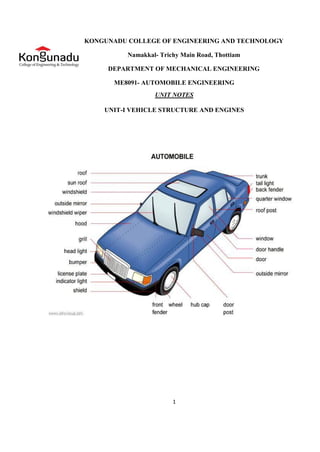
UNIT-I VEHICLE STRUCTURE AND ENGINES
2. 2
1..1. Introduction of Automobile or Vehicle:
An Automobile is a self propelled vehicle which contains the power source
for its propulsion and is used for carrying passengers and goods on the ground, such
as car, bus, trucks, etc.,,
1.2. Types of Automobile;
The automobiles are classified by the following ways,
1. On the Basis of Load:
Heavy transport vehicle (HTV) or heavy motor vehicle (HMV),
Light transport vehicle (LTV), Light motor vehicle (LMV),
2. On the Basis of Wheels :
Two wheeler vehicle, for example : Scooter, motorcycle, scooty, etc.
Three wheeler vehicle, for example : Autorickshaw,
Three wheeler scooter for handicaps and tempo, etc.
Four wheeler vehicle, for example : Car, jeep, trucks, buses, etc.
Six wheeler vehicle, for example : Big trucks with two gear axles.
3. On the basis of Fuel Used:
Petrol vehicle, e.g. motorcycle, scooter, cars, etc.
Diesel vehicle, e.g. trucks, buses, etc.
Electric vehicle which use battery to drive.
Steam vehicle, e.g. an engine which uses steam engine.
Gas vehicle, e.g. LPG and CNG vehicles, where LPG is liquefied
4. On the basis of body style:
Sedan Hatchback car.
Coupe car Station wagon Convertible.
Van Special purpose vehicle, e.g. ambulance, milk van, etc.
5. On the basis of Transmission:
Conventional vehicles with manual transmission, e.g. car with 5 gears.
Semi-automatic
Automatic : In automatic transmission, gears are not required to be
changed manually.
6. On the basis of Drive:
Left hand drive
Right hand drive
7. On the basis of Driving Axle
Front wheel drive
Rear wheel drive
All wheel drive
8. Position of Engine:
Engine in Front - Most of the vehicles have engine in the front. Example :
most of the cars,
Engine in the Rear Side Very few vehicles have engine located in the rear.
Example : Nano car.
3. 3
1.3. Vehicle construction and Components;
The main components of an automobile refer to the following components;
Frame,
Chassis,
Body,
Power unit,
Transmission system.
An automobile is made up of mainly two units, these are Chassis and Body.
―Frame‖ + ―Base components‖ = ―Chassis‖
―Chassis‖ + ―Body‖ = ―Vehicle‖
4. 4
Frame :
The frame is the skeleton of the vehicle. It servers as a main foundation and
base for alignment for the chassis.
Types;
Conventional frame,
Semi integral frame;
Integral or untidiest frame.
Chassis;
If the frame contains the base components its called as chassis. The
components are like Engine, radiator, clutch, gearbox, silencer, road wheels, fuel tank,
wirings, differential units, etc..,
Body:
Types;
Body is the superstructure of the vehicle and it is bolted to the chasis.
Car,
Truck,
Tractor,
Delivery van,
Jeep,
Bus, etc..,
5. 1.4. Resistances to vehicle motion and need for a gearbox
Aerodynamics
Aerodynamics, from Greek ἀήρ aer (air) + δυναμική (dynamics), is a branch
of dynamics concerned with studying the motion of air, particularly when it interacts with
a solid object, such as an airplane wing.
Aerodynamics is a sub-field of fluid dynamics and gas dynamics, and many
aspects of aerodynamics theory are common to these fields. The term aerodynamics is
often used synonymously with gas dynamics, with the difference being that "gas
dynamics" applies to the study of the motion of all gases, not limited to air.
Modern aerodynamics only dates back to the seventeenth century, but
aerodynamic forces have been harnessed by humans for thousands of years in sailboats
and windmills, and images and stories of flight appear throughout recorded history, such
as the Ancient Greek legend of Icarus and Daedalus. Fundamental concepts
of continuum, drag, and pressure gradients, appear in the work
of Aristotle and Archimedes.
Forces of flight on an airfoil
Fundamental Concept
Understanding the motion of air around an object (often called a flow field)
enables the calculation of forces and moments acting on the object. In many
aerodynamics problems, the forces of interest are the fundamental forces of
flight: lift, drag, thrust, and weight. Of these, lift and drag are aerodynamic forces, i.e.
forces due to air flow over a solid body.
Calculation of these quantities is often founded upon the assumption that the flow
field behaves as a continuum. Continuum flow fields are characterized by properties such
as velocity, pressure, density and temperature, which may be functions of spatial position
and time.
These properties may be directly or indirectly measured in aerodynamics
experiments, or calculated from equations for the conservation of mass, momentum, and
energy in air flows. Density, velocity, and an additional property, viscosity, are used to
classify flow fields.
6. 1.5. Components of an Engine;
Even though reciprocating internal combustion engines look quite simple, they
are highly complex machines. There are hundreds of components that have to perform
their functions satisfactorily to produce output power. There are two types of engines,
viz., spark ignition (S1) and compression-ignition (CI) engine. Let us now go through the
important engine components and the nomenclature associated with an engine.
Terms connected with i.c. engines;
Bore: The inside diameter of the cylinder is called bore
Stroke: The linear distance along the cylinder axis between two limiting position
s is called stroke.
Top Dead Center ( T.D.C.) : the top most position of the piston towards cover
end side of the cylinder is called T.D.C.
Bottom dead Center ( B.D.C.) : The lowest position of the piston towards the
crank end side of the cylinder is called B.D.C.
Clearance Volume : The volume contained in the cylinder above the top of the
piston , when the piston is at top dead center , is called the clearance volume.
Swept Volume: The volume swept through by the piston in moving between
T.D.C. and B.D.C, is called swept volume or piston displacement.
Compression Ratio: It is the ratio of Total cylinder volume to clearance volume
Definition of ‘Engine’
An engine is a device, which transforms one form of energy into another form.
Normally, most of the engines convert thermal energy into mechanical work and
therefore they are called ‗heat engines‘.
7. Engine Components
The major components of the engine and their functions are briefly described below.
Cylinder Block:
The cylinder block is the main supporting structure for the various components. The cylinder
of a multicylinder engine is cast as a single unit, called cylinder block. The cylinder head is mounted
on the cylinder block.
The cylinder head and cylinder block are provided with water jackets in the case of water-
cooling with cooling fins in the case of air-cooling. Cylinder head gasket is incorporated between
the cylinder block and cylinder head. The cylinder head is held tight to the cylinder block by number
of bolts or studs. The bottom portion of the cylinder block is called crankcase. A cover called
crankcase, which becomes a sump for lubricating oil is fastened to the bottom of the crankcase. The
inner surface of the cylinder block, which is machined and finished accurately to cylindrical shape,
is called bore or face.
Cylinder
As the name implies it is a cylindrical vessel or space in which the piston makes a
reciprocating motion. The varying volume created in the cylinder during the operation of the engine
is filled with the working fluid and subjected to different thermodynamic processes. The cylinder is
supported in the cylinder block.
Piston
It is a cylindrical component fitted into the cylinder forming the moving boundary of the
combustion system. It fits perfectly (snugly) into the cylinder providing a gas-tight space with the
piston rings and the lubricant. It forms the first link in transmitting the gas forces to the output shaft.
Combustion Chamber
The space enclosed in the upper part of the cylinder, by the cylinder head and the piston top
during the combustion process, is called the combustion chamber. The combustion of fuel and the
consequent release of thermal energy results in the building up of pressure in this part of the
cylinder.
Inlet Manifold
The pipe which connects the intake system to the inlet valve of the engine and through which
air or air-fuel mixture is drawn into the cylinder is called the inlet manifold.
Gudgeon Pin
It forms the link between the small end of the connecting rod and the piston.
8. Exhaust Manifold
The pipe that connects the exhaust system to the exhaust valve of the engine and through
which the products of combustion escape into the atmosphere is called the exhaust manifold.
Inlet and Exhaust Valves
Valves are commonly mushroom shaped poppet type. They are provided either on the
cylinder head or on the side of the cylinder for regulating the charge coming into the cylinder (inlet
valve) and for discharging the products of combustion (exhaust valve) from the cylinder.
Connecting Rod
It interconnects the piston and the crankshaft and transmits the gas forces from the piston to
the crankshaft. The two ends of the connecting rod are called as small end and the big end. Small
end is connected to the piston by gudgeon pin and the big end is connected to the crankshaft by
crankpin.
Crankshaft
It converts the reciprocating motion of the piston into useful rotary motion of the output
shaft. In the crankshaft of a single cylinder engine there is pair of crank arms and balance weights.
The balance weights are provided for static and dynamic balancing of the rotating system. The
crankshaft is enclosed in a crankcase.
Piston Rings
Piston rings, fitted into the slots around the piston, provide a tight seal between the piston
and the cylinder wall thus preventing leakage of combustion gases
Camshaft
The camshaft and its associated parts control the opening and closing of the two valves. The
associated parts are push rods, rocker arms, valve springs and tappets. This shaft also provides the
drive to the ignition system. The camshaft is driven by the crankshaft through timing gears.
Cams
These are made as integral parts of the camshaft and are designed in such a way to open the
valves at the correct timing and to keep them open for the necessary duration.
Fly Wheel
The net torque imparted to the crankshaft during one complete cycle of operation of the
engine fluctuates causing a change in the angular velocity of the shaft. In order to achieve a uniform
torque an inertia mass in the form of a wheel is attached to the output shaft and this wheel is called
the flywheel.
9. Basic Parts of the Gasoline Engine:
Basic Parts of the Gasoline Engine are listed below;
Cylinder block
Piston
Piston rings
Piston pin
Connecting rod
Crankshaft
Cylinder head
Intake valve
Exhaust valve
Camshaft
Timing gears
Spark plug
Cylinder Block:
Cylinder Block Basic frame of gasoline engine. Contains the cylinder.
Piston:
Piston A sliding plug that harnesses the force of the burning gases in the cylinder.
Piston Rings:
Piston rings seal the compression gases above the piston keep the oil below the piston rings.
Piston Pins:
Piston Pins Also known as the wrist pin, it connects the piston to the small end of the
connecting rod. It transfers the force and allows the rod to swing back and forth.
Connecting Rod:
Connecting Rod Connects the piston and piston pin to the crankshaft.
Crankshaft:
Crankshaft Along the the piston pin and connecting rod it converts the up and down motion
(reciprocating) of the engine to spinning (rotary) motion.
Flywheel:
Flywheel Carries the inertia when there is no power stroke.
Cylinder Head:
Cylinder Head Forms the top of the combustion chamber. Contains the valves, the
passageways for the fuel mixture to move in and out of the engine.
Intake and Exhaust Valves:
Intake and Exhaust Valves Doorway that lets the gases in and out of the engine.
Camshaft:
Camshaft Through the use of an eccentric the cam lobes push the valves open. The valve
springs close them.
Timing Gears:
Timing Gears These gears drive the camshaft from the crankshaft.
10. Why not diesel engines are not preferred in commercial ?:
1. Diesel engines, because they have much higher compression ratios (20:1 for a typical diesel
vs. 8:1 for a typical gasoline engine), tend to be heavier than an equivalent gasoline engine.
2. Diesel engines also tend to be more expensive.
3. Diesel engines, because of the weight and compression ratio, tend to have lower maximum
RPM ranges than gasoline engines .This makes diesel engines high torque rather than high
horsepower, and that tends to make diesel cars slow in terms of acceleration.
4. Diesel engines must be fuel injected, and in the past fuel injection was expensive and less
reliable
5. Diesel engines tend to produce more smoke.
6. Diesel engines are harder to start in cold weather, and if they contain glow plugs, diesel
engines can require you to wait before starting the engine so the glow plugs can heat up.
7. Diesel engines are much noisier and tend to vibrate.
8. Diesel fuel is less readily available than gasoline
Advantages diesel engines:
The two things working in favor of diesel engines are better fuel economy and longer engine
life. Both of these advantages mean that, over the life of the engine, you will tend to save money
with a diesel.
However, you also have to take the initial high cost of the engine into account. You have to
own and operate a diesel engine for a fairly long time before the fuel economy overcomes the
increased purchase price of the engine.
The equation works great in a big diesel tractor-trailer rig that is running 400 miles every
day, but it is not nearly so beneficial in a passenger car.
11. 1.6. ENGINE SUPPORT SYSTEMS:
Cooling system
Lubrication system
Fuel and ignition/injection system
Intake system Exhaust system
1.6.1. Cooling system:
The cooling system removes excess heat to keep the inside of the engine at an efficient temperature.
Air Cooling
Liquid Cooling
Water cooling Coolant.
Water Jackets:
Water Jackets Surrounds the cylinders with water passage. Absorbs heat from the cylinder
wall. Pump move water to radiator where heat is exchanged to the air. 66
Coolant Flow:
Coolant flows through the water jackets where it absorbs heat. It then flows through the
radiator where heat is transferred to the air passing through. The amount of flow is determined by
the water pump. The flow direction is controlled by the thermostat.
Warm Engine:
The thermostat opens when the engine warms up. This allows coolant to circulate through
the radiator and the water jackets.
Cold Engine:
When an engine is cold, the thermostat is cold. Coolant flow is through the bypass hose and
the water jackets. This allows the engine to warm up evenly.
Coolant :
Coolant Water (Boiling Point 100° C)
Glycerin (Boiling Point 290 ° C)
Ethylene glycol (Boiling Point 197 ° C)
Antifreeze (methyl alcohol, ethyl alcohol )
Cooling System:
Water pump is driven by the crankshaft through Timing Belt ( Keeps Cam and Crank shafts
in time)
Drive/accessory Belt (Runs alternator, power-steering pump, AC, etc.) Serpentine Belt V-
Belt
Electric fan is mounted on the radiator and is operated by battery power. It is controlled by
the thermostat switch.
12. Need for cooling system
The cooling system has four primary functions. These functions are as follows:
1. Remove excess heat from the engine.
2. Maintain a constant engine operating temperature.
3. Increase the temperature of a cold engine as quickly as possible.
4. Provide a means for heater operation (warming the passenger compartment).
Types of cooling system:
The different Types of cooling system are
1. Air cooling system
2. Liquid cooling system
3. Forced circulation system
4. Pressure cooling system
Air-Cooled System :
The simplest type of cooling is the air-cooled, or direct, method in which the heat is drawn
off by moving air in direct contact with the engine Several fundamental principles of cooling are
embodied in this type of engine cooling. The rate of the cooling is dependent upon the following:
1. The area exposed to the cooling medium.
2. The heat conductivity of the metal used &
the volume of the metal or its size in cross section .
3. The amount of air flowing over the heated surfaces.
4. The difference in temperature between the exposed
metal surfaces and the cooling air.
Liquid-cooled system;
Nearly all multi cylinder engines used in automotive, construction, and material-
handling equipment use a liquid-cooled system. Any liquid used in this type of system is called a
COOLANT.
A simple liquid-cooled system consists of a radiator, coolant pump, piping, fan, thermostat,
and a system of water jackets and passages in the cylinder head and block through which the coolant
circulates. Some vehicles are equipped with a coolant distribution tube inside the cooling passages
that directs additional coolant to the points where temperatures are highest.
Cooling of the engine parts is accomplished by keeping the coolant circulating and in
contact with the metal surfaces to be cooled. The operation of a liquid- cooled system is as follows:
The pump draws the coolant from the bottom of the radiator, forcing the coolant through the
water jackets and passages, and ejects it into the upper radiator tank. The coolant then passes
through a set of tubes to the bottom of the radiator from which the cooling cycle begins.
13. The radiator is situated in front of a fan that is driven either by the water pump or an electric
motor. The fan ensures airflow through the radiator at times when there is no vehicle motion. The
downward flow of coolant through the radiator creates what is known as a thermosiphon action. This
simply means that as the coolant is heated in the jackets of the engine, it expands. As it expands, it
becomes less dense and therefore lighter. This causes it to flow out of the top outlet of the engine
and into the top tank of the radiator. As the coolant is cooled in the radiator, it again becomes more
dense and heavier. This causes the coolant to settle to the bottom tank of the radiator.
The heating in the engine and the cooling in the radiator therefore create a natural
circulation that aids the water pump. The amount of engine heat that must be removed by the
cooling system is much greater than is generally realized. To handle this heat load, it may be
necessary for the cooling system in some engine to circulate 4,000 to 10,000 gallons of coolant per
hour. The water passages, the size of the pump and radiator, and other details are so designed as to
maintain the working parts of the engine at the most efficient temperature within the limitation
imposed by the coolant.
Pressure cooling system
Radiator Pressure Cap
The radiator pressure cap is used on nearly all of the modern engines. The radiator cap locks
onto the radiator tank filler neck Rubber or metal seals make the cap-to-neck joint airtight. The
functions of the pressure cap are as follows:
1. Seals the top of the radiator tiller neck to prevent leakage.
2. Pressurizes system to raise boiling point of coolant.
3. Relieves excess pressure to protect against system damage.
4. In a closed system, it allows coolant flow into and from the coolant reservoir.
The radiator cap pressure valve consists of a spring- loaded disc that contacts the filler neck.
The spring pushes the valve into the neck to form a seal. Under pressure, the boiling point of water
increases. Normally water boils at 212°F.
However, for every pound of pressure increase, the boiling point goes up 3°F. Typical
radiator cap pressure is 12 to 16 psi. This raises the boiling point of the engine coolant to about
250°F to 260°F. Many surfaces inside the water jackets can be above 212°F. If the engine
overheats and the pressure exceeds the cap rating, the pressure valve opens. Excess pressure forces
coolant out of the overflow tube and into the reservoir or onto the ground.
This prevents high pressure from rupturing the radiator, gaskets, seals, or hoses. The
radiator cap vacuum valve opens to allow reverse flow back into the radiator when the coolant
temperature drops after engine operation. It is a smaller valve located in the center, bottom of the
cap.
The cooling and contraction of the coolant and air in the system could decrease coolant
volume and pressure. Outside atmospheric pressure could then crush inward on the hoses and
radiator. Without a cap vacuum or vent valve, the radiator hose and radiator could collapse
14. .6.2. Lubrication System:
Parts require lubrications Crankshaft bearing Piston pin Timing gears Valve mechanism
Piston ring and cylinder walls Camshaft and bearings.
Purpose of lubrication:
Reduce friction & wear - by creating a thin film (Clearance) between moving parts
Seal power - The oil helps form a gastight seal between piston rings and cylinder walls
Cleaning - Cleans As it circulates through the engine, the oil picks up metal particles and
carbon, and brings them back down to the pan.
Absorb shock - When heavy loads are imposed on the bearings, the oil helps to cushion the
load
Cooling. - Cools Picks up heat when moving through the engine and then drops into the
cooler oil pan, giving up some of this heat.
Types Lubrication System:
Petroil system
Splash system
Pressure system
Dry-sump system
Oil change:
Every 5000Km for four wheeler , Every 2000 Km in two wheeler Ignoring regular oil change
intervals will shorten engine life and performance.
All internal combustion engines are equipped with an internal lubricating system. Without
lubrication, an engine quickly overheats and its working parts seize due to excessive friction. All
moving parts must be adequately lubricated to assure maximum wear and long engine life.
Purpose of Lubrication;
The functions of an engine lubrication system are as follows: Reduces friction and wear
between moving parts. Helps transfer heat and cool engine parts. Cleans the inside of the engine by
removing contaminants (metal, dirt, plastic, rubber, and other particles).
Absorbs shocks between moving parts to quiet engine operation and increase engine life. The
properties of engine oil and the design of modern engines allow the lubrication system to accomplish
these functions.
15. Types of Lubrication Systems;
Now that you are familiar with the lubricating system components, you are ready to study the
different systems that circulate oil through the engine. The systems used to circulate oil are known
as splash, combination splash force feed, force feed, and full force-feed.
Splash Systems
The splash system is no longer used in automotive engines. It is widely used in small four-
cycle engines for lawn mowers, outboard marine operation, and so on. In the splash lubricating
system, oil is splashed up from the oil pan or oil trays in the lower part of the crankcase.
The oil is thrown upward as droplets or fine mist and provides adequate lubrication to valve
mechanisms, piston pins, cylinder walls, and piston rings. In the engine, dippers on the
connecting-rod bearing caps enter the oil pan with each crankshaft revolution to produce the oil
splash.
A passage is drilled in each connecting rod from the dipper to the bearing to ensure
lubrication. This system is too uncertain for automotive applications. One reason is that the level
of oil in the crankcase will vary greatly the amount of lubrication received by the engine. A high
level results in excess lubrication and oil consumption and a slightly low level results in inadequate
lubrication and failure of the engine.
Combination Splash and Force Feed
In a combination splash and force feed, oil is delivered to some parts by means of splashing
and other parts through oil passages under pressure from the oil pump. The oil from the pump enters
the oil galleries. From the oil galleries, it flows to the main bearings and camshaft bearings.
The main bearings have oil-feed holes or grooves that feed oil into drilled passages in the
crankshaft. The oil flows through these passages to the connecting rod bearings. From there, on
some engines, it flows through holes drilled in the connecting rods to the piston-pin bearings.
Cylinder walls are lubricated by splashing oil thrown off from the connecting-rod bearings.
Some engines use small troughs under each connecting rod that are kept full by small nozzles
which deliver oil under pressure from the oil pump. These oil nozzles deliver an increasingly heavy
stream as speed increases. At very high speeds these oil streams are powerful enough to strike the
dippers directly. This causes a much heavier splash so that adequate lubrication of the pistons and
the connecting-rod bearings is provided at higher speeds. If a combination system is used on an
overhead valve engine, the upper valve train is lubricated by pressure from the pump.
Force Feed
A somewhat more complete pressurization of lubrication is achieved in the force-feed
lubrication system. Oil is forced by the oil pump from the crankcase to the main bearings and the
camshaft bearings. Unlike the combination system the connecting-rod bearings are also fed oil
under pressure from the pump. Oil passages are drilled in the crankshaft to lead oil to the
connecting-rodbearings.
16. The passages deliver oil from the main bearing journals to the rod bearing journals. In
some engines, these opening are holes that line up once for every crankshaft revolution. In other
engines, there are annular grooves in the main bearings through which oil can feed constantly
into the hole in the crankshaft. The pressurized oil that lubricates the connecting- rod bearings goes
on to lubricate the pistons and walls by squirting out through strategically drilled holes. This
lubrication system is used in virtually all engines that are equipped with semi floating piston pins.
Full Force Feed
In a full force-feed lubrication system, the main bearings, rod bearings, camshaft bearings,
and the complete valve mechanism are lubricated by oil under pressure. In addition, the full
force-feed lubrication system provides lubrication under pressure to the pistons and the piston pins.
This is accomplished by holes drilled the length of the connecting rod, creating an oil
passage from the connecting rod bearing to the piston pin bearing. This passage not only feeds the
piston pin bearings but also provides lubrication for the pistons and cylinder walls. This system is
used in virtually all engines that are equipped with full-floating piston pins.
Four-stroke Spark-ignition Engine
In a four-stroke engine, the cycle of operations is completed in four strokes of the piston or
two revolutions of the crankshaft. During the four strokes, there are five events to be completed, viz,
suction, compression, combustion, expansion and exhaust. Each stroke consists of 180° of
crankshaft rotation and hence a four-stroke cycle is completed through 720° of crank rotation. The
cycle of operation for an ideal four-stroke SI engine consists of the following four strokes:
i. Suction or intake stroke;
ii. Compression stroke;
iii. Expansion or power stroke and
iv. Exhaust stroke.
Working principle of a Four Stroke SI Engine
i. Suction or Intake Stroke: Suction stroke starts when the piston is at the top dead centre and
about to move downwards. The inlet valve is open at this time and the exhaust valve is closed. Due
to the suction created by the motion of the piston towards the bottom dead centre, the charge
consisting of fuel-air mixture is drawn into the cylinder. When the piston reaches the bottom dead
centre the suction stroke ends and the inlet valve closes.
ii. Compression Stroke: The charge taken into the cylinder during the suction stroke is
compressed by the return stroke of the piston. During this stroke both inlet and exhaust valves are in
closed position. The mixture that fills the entire cylinder volume is now compressed into the
17. clearance volume. At the end of the compression stroke the mixture is ignited with the help of a
spark plug located on the cylinder head. In ideal engines it is assumed that burning takes place
instantaneously when the piston is at the top dead centre and hence the burning process can be
approximated as heat addition at constant volume.
During the burning process the chemical energy of the fuel is converted into heat energy
producing a temperature rise of about 2000 °C. The pressure at the end of the combustion process is
considerably increased due to the heat release from the fuel.
iii. Exhaust Stroke: At the end of the expansion stroke the exhaust valve opens and the inlet
valve remains closed. The pressure falls to atmospheric level a part of the burnt gases escape. The
piston starts moving from the bottom dead centre to top dead centre and sweeps the burnt gases out
from the cylinder almost at atmospheric pressure.
The exhaust valve closes when the piston reaches T.D.C. at the end of the exhaust stroke and
some residual gases trapped in the clearance volume remain in the cylinder. Residual gases mix with
the fresh charge coming in during the following cycle, forming its working fluid.
Each cylinder of a four stroke engine completes the above four operations in two engine
revolutions, one revolution of the crankshaft occurs during the suction and compression strokes and
the second revolution during the power and exhaust strokes. Thus for one complete cycle there‘s
only one power stroke while the crankshaft
turns by two revolutions.
Consumption of lubricating oil is high in two-stroke engines due to higher temperature. A
detailed comparison of two-stroke and four-stroke engines is given in the Table below
18. UNIT-II
ENGINE AUXILIARY SYSTEMS
The fuel feed system for the Spark ignition engines and Compression ignition engines are
clearly discussed below.
2.1. Fuel Injection system for SI engines;
2.1.1. Carburetion
Spark-ignition engines normally use volatile liquid fuels. Preparation of fuel-air mixture is
done outside the engine cylinder and formation of a homogeneous mixture is normally not
completed in the inlet manifold. Fuel droplets, which remain in suspension, continue to evaporate
and mix with air even during suction and compression processes. The process of mixture preparation
is extremely important for spark-ignition engines. The purpose of carburetion is to provide a
combustible mixture of fuel and air in the required quantity and quality for efficient operation of the
engine under all conditions.
Definition of Carburetion;
The process of formation of a combustible fuel-air mixture by mixing the proper amount of
fuel with air before admission to engine cylinder is called carburetion and the device which does this
job is called a carburetor.
Definition of Carburetor;
The carburetor is a device used for atomizing and vaporizing the fuel and mixing it with the
air in varying proportions to suit the changing operating conditions of vehicle engines.
Factors Affecting Carburetion
Of the various factors, the process of carburetion is influenced by
i. The engine speed
ii. The vaporization characteristics of the fuel
iii. The temperature of the incoming air and
iv. The design of the carburetor
19. Principle of Carburetion
Both air and gasoline are drawn through the carburetor and into the engine cylinders by the
suction created by the downward movement of the piston. This suction is due to an increase in the
volume of the cylinder and a consequent decrease in the gas pressure in this chamber.
It is the difference in pressure between the atmosphere and cylinder that causes the air to
flow into the chamber. In the carburetor, air passing into the combustion chamber picks up
discharged from a tube. This tube has a fine orifice called carburetor jet that is exposed to the air
path.
The rate at which fuel is discharged into the air depends on the pressure difference or
pressure head between the float chamber and the throat of the venturi and on the area of the outlet of
the tube. In order that the fuel drawn from the nozzle may be thoroughly atomized, the suction effect
must be strong and the nozzle outlet comparatively small. In order to produce a strong suction, the
pipe in the carburetor carrying air to the engine is made to have a restriction. At this restriction
called throat due to increase in velocity of flow, a suction effect is created. The restriction is made in
the form of a venturi to minimize throttling losses.
The end of the fuel jet is located at the venturi or throat of the carburetor. The geometry of
venturi tube is as shown in Fig.16.6. It has a narrower path at the center so that the flow area through
which the air must pass is considerably reduced. As the same amount of air must pass through every
point in the tube, its velocity will be greatest at the narrowest point. The smaller the area, the greater
will be the velocity of the air, and thereby the suction is proportionately increased
As mentioned earlier, the opening of the fuel discharge jet is usually loped where the suction
is maximum. Normally, this is just below the narrowest section of the venturi tube. The spray of
gasoline from the nozzle and the air entering through the venturi tube are mixed together in this
region and a combustible mixture is formed which passes through the intake manifold into the
cylinders. Most of the fuel gets atomized and simultaneously a small part will be vaporized.
Increased air velocity at the throat of the venturi helps he rate of evaporation of fuel. The difficulty
of obtaining a mixture of sufficiently high fuel vapour-air ratio for efficient starting of the engine
and for uniform fuel-air ratio indifferent cylinders (in case of multi cylinder engine) cannot be fully
met by the increased air velocity alone at the venturi throat.
20. 2.1.2. The Simple Carburetor
Carburetors are highly complex. Let us first understand the working principle bf a simple or
elementary carburetor that provides an air fuel mixture for cruising or normal range at a single
speed. Later, other mechanisms to provide for the various special requirements like starting, idling,
variable load and speed operation and acceleration will be included. Figure 3. shows the details of a
simple carburetor.
The simple carburetor mainly consists of a float chamber, fuel discharge nozzle and a
metering orifice, a venturi, a throttle valve and a choke. The float and a needle valve system
maintain a constant level of gasoline in the float chamber. If the amount of fuel in the float chamber
falls below the designed level, the float goes down, thereby opening the fuel supply valve and
admitting fuel. When the designed level has been reached, the float closes the fuel supply valve thus
stopping additional fuel flow from the supply system. Float chamber is vented either to the
atmosphere or to the‖ upstream side of the venturi.During suction stroke air is drawn through the
venturi.
As already described, venturi is a tube of decreasing cross-section with a minimum area at
the throat, Venturi tube is also known as the choke tube and is so shaped that it offers minimum
resistance to the air flow. As the air passes through the venturi the velocity increases reaching a
maximum at the venturi throat. Correspondingly, the pressure decreases reaching a minimum. From
the float chamber, the fuel is fed to a discharge jet, the tip of which is located in the throat of the
venturi. Because of the differential pressure between the float chamber and the throat of the venturi,
known as carburetor depression, fuel is discharged into the air stream.
Figure: 3 The Simple Carburetor
21. The fuel discharge is affected by the size of the discharge jet and it is chosen to give the
required air-fuel ratio. The pressure at the throat at the fully open throttle condition lies between 4 to
5 cm of Hg, below atmospheric and seldom exceeds8 cm Hg below atmospheric. To avoid overflow
of fuel through the jet, the level of the liquid in the float chamber is maintained at a level slightly
below the tip of the discharge jet. This is called the tip of the nozzle. The difference in the height
between the top of the nozzle and the float chamber level is marked h in Fig.3.
The gasoline engine is quantity governed, which means that when power output is to be
varied at a particular speed, the amount of charge delivered to the cylinder is varied. This is achieved
by means of a throttle valve usually of the butterfly type that is situated after the venturi tube.
As the throttle is closed less air flows through the venturi tube and less is the quantity of air-
fuel mixture delivered to the cylinder and hence power output is reduced. As the‖ throttle is opened,
more air flows through the choke tube resulting in increased quantity of mixture being delivered to
the engine. This increases the engine power output. A simple carburetor of the type described above
suffers from a fundamental drawback in that it provides the required A/F ratio only at one throttle
position.
At the other throttle positions the mixture is either leaner or richer depending on whether the
throttle is opened less or more. As the throttle opening is varied, the air flow varies and creates a
certain pressure differential between the float chamber and the venturi throat. The same pressure
differential regulates the flow of fuel through the nozzle. Therefore, the velocity of flow of air II and
fuel vary in a similar manner.
The Choke and the Throttle
When the vehicle is kept stationary for a long period during cool winter seasons, may be
overnight, starting becomes more difficult. As already explained, at low cranking speeds and intake
temperatures a very rich mixture is required to initiate combustion. Some times air-fuel ratio as rich
as 9:1 is required. The main reason is that very large fraction of the fuel may remain as liquid
suspended in air even in the cylinder. For initiating combustion, fuel-vapour and air in the form of
mixture at a ratio that can sustain combustion is required.
It may be noted that at very low temperature vapour fraction of the fuel is also very small
and this forms combustible mixture to initiate combustion. Hence, a very rich mixture must be
supplied. The most popular method of providing such mixture is by the use of choke valve. This is
simple butterfly valve located between the entrance to the carburetor and the venturi throat as shown
in Fig.3.
When the choke is partly closed, large pressure drop occurs at the venturi throat that would
normally result from the quantity of air passing through the venturi throat. The very large depression
at the throat inducts large amount of fuel from the main nozzle and provides a very rich mixture so
that the ratio of the evaporated fuel to air in the cylinder is within the combustible limits.
Sometimes, the choke valves are spring loaded to ensure that large carburetor depression and
excessive choking does not persist after the engine has started, and reached a desired speed.
22. This choke can be made to operate automatically by means of a thermostat so that the choke
is closed when engine is cold and goes out of operation when engine warms up after starting. The
speed and the output of an engine is controlled by the use of the throttle valve, which is located on
the downstream side of the venturi.
The more the throttle is closed the greater is the obstruction to the flow of the mixture placed
in the passage and the less is the quantity of mixture delivered to .the cylinders. The decreased
quantity of mixture gives a less powerful impulse to the pistons and the output of the engine is
reduced accordingly. As the throttle is opened, the output of the engine increases. Opening the
throttle usually increases the speed of the engine. But this is not always the case as the load on the
engine is also a factor. For example, opening the throttle when the motor vehicle is starting to climb
a hill may or may not increase the vehicle speed, depending upon the steepness of the hill and the
extent of throttle opening. In short, the throttle is simply a means to regulate the output of the engine
by varying the quantity of charge going into the cylinder.
Compensating Devices
An automobile on road has to run on different loads and speeds. The road conditions play a
vital role. Especially on city roads, one may be able to operate the vehicle between 25 to 60% of the
throttle only. During such conditions the carburetor must be able to supply nearly constant air-fuel
ratio mixture that is economical (16:1).However, the tendency of a simple carburetor is to
progressively richen the mixture as the throttle starts opening.
The main metering system alone will not be sufficient to take care of the needs of the engine.
Therefore, certain compensating devices are usually added in the carburetor along with the main
metering system so as to supply a mixture with the required air-fuel ratio. A number of
compensating devices are in use. The important ones are
i. Air-bleed jet
ii. Compensating jet
iii. Emulsion tube
iv. Back suction control mechanism
v. Auxiliary air valve
vi. Auxiliary air port
As already mentioned, in modern carburetors automatic compensating devices are provided
to maintain the desired mixture proportions at the higher speeds. The type of compensation
mechanism used determines the metering system of the carburetor. The principle of operation of
various compensating devices are discussed briefly in the following sections.
23. Air-bleed jet
Figure: 4 Air bleed principle in a typical carburetor
Figure 4. illustrates a principle of an air-bleed system in atypical modern downdraught
carburetor. As could be seen it contains an air-bleed into the main nozzle. An orifice restricts the
flow of air through this bleed and therefore it is called restricted air-bleed jet that is very popular.
When the engine is not operating the main jet and the air bleed jet will be filled with fuel. When the
engine starts, initially the fuel starts coming through the main as well as the air bleed jet (A). As the
engine picks up, only air starts coming through the air bleed and mixes with fuel at B making a air
fuel emulsion.
Thus the fluid stream that has become an emulsion of air and liquid has negligible viscosity
and surface tension. Thus the flow rate of fuel is augmented and more fuel is sucked at low suctions.
‗By proper design of hole size at B compatible with the entry hole at A, it is possible to maintain a
fairly uniform mixture ratio for the entire power range of the operation of an engine. If the fuel flow
nozzle of the air-bleed system is placed in the centre of the venturi, both the air-bleed nozzle and the
venturi are subjected to same engine suction resulting approximately same fuel-air mixture for the
entire power range of operation.
Compensating Jet
Figure: 5 Compensating Jet device
24. The principle of compensating jet device is to make the mixture leaner as the throttle opens
progressively. In this method, as can be seen from Fig.5 in addition to the main jet, a compensating
jet is incorporated. The compensating jet is connected to the compensation well. The compensating
well is also vented to atmosphere like the main float chamber.
The compensating well is supplied with fuel from the main float chamber through a
restricting orifice. With the increase in airflow rate, there is decrease of fuel level in the
compensating well, with the result that fuel supply through the compensating jet decreases. The
compensating jet thus progressively makes the mixture leaner as the main jet progressively makes
the mixture richer. The main jet curve and the compensating jet curve are more or less reciprocals of
each other.
Emulsion Tube
The mixture correction is attempted by air bleeding in modern carburetor. In one such
arrangement as shown in Fig.6, the main metering jet is kept at a level of about 25 mm below the
fuel level in the float chamber. Therefore, it is also called submerged jet. The jet is located at the
bottom of a well. The sides of the well have holes. As can be seen from the figure these holes are in
communication with the atmosphere. In the beginning the level of petrol in the float chamber and the
well is the same.
Figure: 6 Emulsion Tube
When the throttle is opened the pressure at the venturi throat decreases and petrol is drawn
into the air stream. This results in progressively uncovering the holes in the central tube leading to
increasing air-fuel ratios or decreasing richness of mixture when all holes have been uncovered.
Normal flow takes place from the main jet. The air is drawn through these holes in the well, and the
fuel is emulsified and the pressure differential across the column of fuel is not as high as that in
simple carburetor.
25. Acceleration Pump System
Acceleration is a transient phenomenon. In order to accelerate the vehicle and consequently
its engine, the mixture required is very rich and the richness of the mixture has to be obtained
quickly and very rapidly. In automobile engines situations arise when it is necessary to accelerate
the vehicle. This requires an increased output from the engine in a very short time.
If the throttle is suddenly opened there is a corresponding increase in the air flow. However,
because of the inertia of the liquid fuel, the fuel flow does not increase in proportion to the increase
in air flow. This results in a temporary lean mixture ca11singtheengine to misfire and a temporary
reduction in power output.
To prevent this condition, all modern carburetors are equipped with an accelerating system.
Figure 7. illustrates simplified sketch of one such device. The pump comprises of a spring loaded
plunger that takes care of the situation with the rapid opening of the throttle valve. The plunger
moves into the cylinder and forces an additional jet of fuel at the venturi throat.
When the throttle is partly open, the spring sets the plunger back. There is also an
arrangement which ensures that fuel in the pump cylinder is not forced through the jet when valve is
slowly opened or leaks past the plunger or some holes into the float chamber.
Mechanical linkage system, in some carburetor, is substituted by an arrangement where by
the pump plunger is held up by manifold vacuum. When this vacuum is decreased by rapid opening
of the throttle, a spring forces the plunger down pumping the fuel through the jet.
Figure: 7 Acceleration pump system
26. 2.1.3. Types of Carburetors
There are three general types of carburetors depending on the direction of flow of air. The
first is the up draught type shown in Fig.8(a) in which the air enters at the bottom and leaves at the
top so that the direction of its flow is upwards. The disadvantage of the up draught carburetor is that
it must lift the sprayed fuel droplet by air friction. Hence, it must be designed for relatively small
mixing tube and throat so that even at low engine speeds the air velocity is sufficient to lift and carry
the fuel particles along. Otherwise, the fuel droplets tend to separate out providing only a lean
mixture to the engine. On the other hand, the mixing tube is finite and small then it cannot supply
mixture to the engine at a sufficiently rapid rate at high speeds.
Figure: 8 Types of Carburetors
In order to overcome this drawback the downdraught carburetor [Fig.8 (b)] is adopted. It is
placed at a level higher than the inlet manifold and in which the air and mixture generally follow a
downward course. Here the fuel does not have to be lifted by air friction as in the up draught
carburetors but move into the cylinders by gravity even if the air velocity is low. Hence, the mixing
tube and throat can be made large which makes high engine speeds and high specific outputs
possible.
Constant Choke Carburetor:
In the constant choke carburetor, the air and fuel flow areas are always maintained to be
constant. But the pressure difference or depression, which causes the flow of fuel and air, is being
varied as per the demand on the engine. Solex and Zenith carburetors belong to this class.
Constant Vacuum Carburetor:
In the constant vacuum carburetor, (sometimes called variable choke carburetor) air and fuel
flow areas are being varied as per the demand on the engine, while the vacuum is maintained to be
always same. The S.U. and Carter carburetors belong to tills class.
27. Multiple Venturi Carburetor:
Multiple venturi system uses double or triple venturi. The boost venturi is located
concentrically within the main venturi.The discharge edge of the boost venturi is located at the
throat of the main venturi. The boost venturi is positioned upstream of the throat of the larger main
venturi. Only a fraction of the total air flows though the boost venturi. Now the pressure at the boost
venturi exit equals the pressure at the main venturi throat. The fuel nozzle is located at the throat of
the boost venturi.
2.2. Fuel Injection system for C I engines;
Fuel system components FUEL INJECTION PUMP - Fuel injection pump sucks fuel from
the tank , pressurizes the fuel to approx. 600 - 1000 bar and sends it to the injectors. Inline FIP - Has
separate pumping chambers for each cylinder Rotary FIP (Distributor pump) - Has one pumping
chamber and the pump distributes to each cylinder as per sequence- firing order INJECTORS -
Inject the high pressure fuel in to each cylinder. FUEL FILTER - Filters the fuel from dirt &
sediments, since the Fuel injection pump requires clean fuel.
Injection system In the C.I. engine the fuel is injected into the combustion chamber, it the has
to mix thoroughly with the air, ignite and burn all at the same time. To insure this happens, two
types of combustion chamber have been developed. Direct Injection Indirect Injection
2.2.1. Electronic Diesel Control
Electronic Diesel Control is a diesel engine fuel injection control system for the precise
metering and delivery of fuel into the combustion chamber of modern diesel engines used
in trucks and cars.
EDC injection inline pump
28. The mechanical fly-weight governors of inline and distributor diesel fuel
injection pumps used to control fuel delivery under a variety of engine loads and conditions could no
longer deal with the ever increasing demands for efficiency, emission control, power and fuel
consumption.
These demands are now primarily fulfilled by the Electronic Control, the system which
provides greater ability for precise measuring, data processing, operating environment flexibility and
analysis to ensure efficient diesel engine operation. The EDC replaces the mechanical control
governor with an electro-magnetic control device.
2.2.2. Components in Electronically controlled Diesel Supply;
The EDC is divided into these main groups of components.
Electronic sensors for registering operating conditions and changes. A wide array
of physical inputs is converted into electrical signal outputs.
Actuators or solenoids which convert the control unit's electrical output signal into
mechanical control movement.
ECM (Electronic Control Module ) or Engine ECU (Electronic Control Unit) with
microprocessors which process information from various sensors in accordance with
programmed software and outputs required electrical signals into actuators and solenoids.
EDC accelerator pedal assembly
1. Electronic sensors;
Injection pump speed sensor - monitors pump rotational speed
Fuel rack position sensor - monitors pump fuel rack position
Charge air pressure sensor - measures pressure side of the turbocharger
Fuel pressure sensor
Air cleaner vacuum pressure sensor
Engine position sensor
Temperature sensors - measure various operating temperatures
29. Intake temperature
Charge air temperature
Coolant temperature
Fuel temperature
Exhaust temperature (Pyrometer)
Ambient temperature
Vehicle speed sensor - monitors vehicle speed
Brake pedal sensor - operates with cruise control, exhaust brake, idle control
Clutch pedal sensor - operates with cruise control, exhaust brake, idle control
Accelerator pedal sensor.
2.Electronic Control Unit;
ECU control unit
The ECU collects and processes signals from various on-board sensors. An ECU electronic
module contains microprocessors, memory units, analog to digital converters and output interface
units. Depending upon the parameters, a number of different maps can be stored in the on board
memory.
This allows the ECU to be tailored to the specific engine and vehicle requirements,
depending on the application. The operating software of the ECU can be adapted for a wide variety
of engines and vehicles without the necessity of hardware modification.
The ECU is usually located in the cab or in certain cases, in a suitable position in
the engine bay where additional environmental conditions might require cooling of the ECU as well
as a requirement for better dust, heat and vibrations insulation .
30. 3. Actuators and Solenoids
Electro-magnetic actuators are usually located on the fuel pump to transfer electrical signals
into mechanical action in this case fuel rack actuator and or fuel stop solenoid which means that
depending on requests from control unit full fuel or no fuel quantity.
EDC pump actuator
Injectors
Boost-pressure actuator
Intake-duct switchoff
Throttle-valve actuator
Exhaust-gas recirculation actuator
Auxiliary heating
A/C compressor
Radiator fan
Electronic shutoff valve
Rail-pressure control valve
Diagnosis lamp
31. Working Principle;
The injection of fuel or the quantity of injected fuel has a decisive influence on engine
starting, idling, power and emissions. The engine ECU is programmed ("mapped") with relevant
data to where the fuel rack position has an equivalent signal for the amount of fuel being injected.
The driver requests the torque or engine speed requirements via accelerator pedal
potentiometer thereby sending a signal to the engine ECU which then, depending on its mapping and
data collected from various sensors, calculates in real time the quantity of injected fuel required, thus
altering the fuel rack to the required position. The driver can also input additional commands such as
idle speed increase to compensate e.g. for PTO operation which can be either variably set or has a
preset speed which can be recalled.
The road speed function can be used to evaluate vehicle speed and possibly activate a speed
limiter (Heavy Vehicles), or maintain or restore a set speed (cruise control). Further functions can
include exhaust brake operation which, when activated, will result in the fuel pump rack position
being set to zero delivery or idle. The engine ECU can also interface with various other vehicle
systems e.g. traction control and carries out self monitoring duties and self diagnostic functions to
keep the system working at an optimal level. To ensure the safe operation in case of failure, the limp
home mode functions are also integrated into the system, for e.g. should the pump speed sensor fail
the ECU can use an alternator speed signal function for engine RPMs counter as a backup signal.
32. 2.2.3. .Fuel Injector:
Fuel injection is a system for admitting fuel into an internal combustion engine. It has
become the primary fuel delivery system used in automotive engines, having
replaced carburetors during the 1980s and 1990s. A variety of injection systems have existed since
the earliest usage of the internal combustion engine.
The primary difference between carburetors and fuel injection is that fuel
injection atomizes the fuel by forcibly pumping it through a small nozzle under high pressure, while
a carburetor relies on suction created by intake air accelerated through a Venturi tube to draw the
fuel into the airstream.
Modern fuel injection systems are designed specifically for the type of fuel being used. Some
systems are designed for multiple grades of fuel (using sensors to adapt the tuning for the fuel
currently used). Most fuel injection systems are for gasoline or diesel applications.
33. 2.3. Introduction of Ignition System;
For petrol engine - Battery ignition system , Magneto ignition system Injection system
For diesel engine - Fuel supply system.
Battery ignition system:
Battery ignition system has the following elements
Primary Ignition Circuit(low voltage)
Battery
Ignition switch
Primary windings of coil
Contact breaker
capacitor
Secondary Ignition Circuit ( high voltage)
Secondary windings of coil
Distributor cap and rotor (if the vehicle is so equipped)
Spark plug wires &
Spark plugs
IGNITION SYSTEM – Magneto System Ignition Switch Distribution Contact Breaker Coil
Magneto Condenser Power Generation Spark Generation Magneto Unit Rotor Arm
IGNITION SYSTEM – Dynamo/Alternator System Dynamo/ Alternator Distributor Contact
Breaker Coil Ignition Switch Secondary Windings Primary Windings Condenser Battery
Ignition Switch Coil Packs IGNITION SYSTEM – Electronic Systems Control Unit Timing Sensor
Timing Disc Engine Speed Sensing Unit Alternator Battery
In all spark ignition engines which work on the Gasoline either 2-Stroke or 4-Stroke cycle
principle and utilize a carburetor or fuel injection system, the combustion of the air-fuel mixture is
initiated by an electric spark.
The term ‗Spark Ignition‘ means that a brief electric arc is produced between the electrodes
of a spark plug, the energy for which is derived from an external power source. In most cases this
power source is the vehicle battery, which is constantly being supplemented by the alternate while
the vehicle is mobile.
A different method of ignition is employed in diesel engines. This is called ‗compression
ignition‘ and relies on the fact that when air compressed, its temperature rises. In diesel engines,
compression ratio of between 16:1 and 25:1 are common, and at the end of a compression the
temperature of the trapped air is sufficiently high to ignite the diesel fuel that is sprayed into the
cylinder at the appropriate time.
34. The functions of ignition system
The functions of the coil ignition systems in general use on motor vehicle may be divided into
three areas. These are:
Production of the high voltage necessary to produce a spark at the plug gap.
Distribute the spark to all the cylinders at proper time based on the firing order.
Varying the timing of the spark depending on the various operating conditions of the engine
like cranking time, varying speed and load, so that the best performance is obtained from the
engine under all operating conditions.
Mechanism of Ignition
It must be remembered that vehicle battery voltages are usually 12 volt or 24 volt and this
value is too low to produce a heavy spark at the plug gap in a cylinder under compression. For this
reason one of the major functions of the battery ignition system is to raise the battery voltage to the
required level and then apply it to spark plugs.
This process is correctly initiated in the primary circuit and completed in the secondary
winding of the ignition coil. Depending on the type of engine and the conditions existing in the
cylinders, a voltage of between 5,000 to 20,000 volts is required and this is called the ionizing
voltage or firing voltage.
This firing voltage forces the electrons to jump between the electrodes of the spark plug in
the gap to produce the required spark. The electric spark has sufficient heat energy to ignite the air-
fuel mixture which later continues to burn itself.
The conventional coil ignition system
Inductive ignition systems: that uses an ignition coil to perform the step up transformer
action and to increase the electrical voltage. The ignition coils of the inductive ignition systems
operate on the principle of electromagnetic induction (EMI) irrespective of whether it is triggered by
contact breakers or by electronic triggering units.
Note:
As a reminder of the principle of EMI, a voltage will be induced into a coil whenever the
following factors are present:
(a) a magnetic field
(b) a set of conductors
(c) a relative movement between the magnetic field and conductors.
35. _
The factors affecting the operation of the Ignition system.
` The factors that determine the value of the voltages induced into the ignition coil windings
during the ignition cycle are:
(a) The strength of the magnetic field.
The stronger the magnetic field produced in the coil primary winding, the greater the
possibility of producing a high secondary voltage.
(b) The number of conductors on the secondary winding being cut by the magnetic field. This
isimportant when considering the voltages produced in both coil windings during the ignition
cycle.
(c) The speed of relative movement
between the magnetic field and +
the conductors. The faster the
magnetic field can be made to
cut the conductors, the higher
will be the value of voltage
induced into the coil windings.
Construction of the Ignition coil Ignition Coil
HT Outlet
Primary
winding
Secondary
winding
Soft Iron core
Oil filled for
Cooling
Soft iron
Cover
The source of the high voltage pulses of current produced in the inductive ignition system is
in the ignition coil. The coil stores the energy in the magnetic field around the primary winding and
at the required instant of ignition, transforms it into a pulse of high voltage current in the secondary
winding. From here it is delivered to the correct spark plug via the high tension (HT) cables. This
‗Inductive storage device‘ may vary in design between certain manufacturers, but in general the
most common construction is as shown in figure below.
This coil contains a rod shaped, laminated soft iron core at its centre, and the soft iron cover
surrounds both primary and secondary windings. Both of these soft iron components are used to
intensify and maximize the effect of the primary magnetic field and thus, the energy stored. The
iron core must be laminated to minimize the effects of eddy currents that are produced during
operation and so keep to a minimum the heat developed. The outer soft iron cover is slotted to allow
circulation of the oil filling which is used for cooling purposes.
36. Around the laminated core, the secondary winding is wounded. This consists of many turns
of very fine insulated copper wire (generally in the vicinity of 20,000 turns). One end of this
winding is connected to the HT outlet of the coil via the laminated iron core which it used as the
pick-up point for this connection. The other end is connected to the positive (+) low tension primary
terminal.
Over the top of the secondary winding the primary winding is wounded with the insulation.
The primary winding consisting of a few hundred turns of relatively heavy insulated copper wire.
The ends of the primary winding are connected to the two low tension, or primary terminals. A
reason for placing the primary winding over the secondary is that it is in this coil, which caries the
full primary circuit current (approximately 2 ampere in standard systems), the secondary winding
generates the heat and by placing it thus, the cooling oil is given ready access to it.
A ceramic insulator at the base of the coil supports the core and winding and at the top is a
plastic-type insulator which provides a location point for the high-tension and primary terminals.
This top insulator is sealed into the outer case to prevent the loss of coolant oil or the energy of
moisture.
Operation of an Ignition coil
Electromagnetic induction is the effect of creating the voltage in a conductor by means of
relative movement between the conductor and a magnetic field. In the ignition coil the conductors
remain stationary and the magnetic field is moved across them. To develop these necessary
conditions, the first requirement in the ignition oil is the production of a magnetic field. This is the
function of the primary winding.
When the ignition switch is closed, the primary winding of the coil is connected to the
positive terminal of the vehicle battery. Now, if the primary circuit is completed through the contact
breaker points a current will flow in the circuit, creating a magnetic field in the coil around the soft
iron core. This magnetic field grows outwards from the core until it has reached maximum value
and the core is fully magnetized and ceases to grow further.
37
Growing Magnetic field
37. To provide the very high voltage necessary to create a spark across the plug gap, the
secondary winding has a very large number of turns. NOTE: The ratio of the number of
secondary turns to the number of primary turns is very large – approximately 100:1. The effect of
this high ration is to produce a very high voltage in the secondary winding when the magnetic field
is collapsed rapidly across it as the contact breaker points are opened.
To understand the operation of the ignition coil, it is necessary to have the knowledge of the
effect of winding insulated wire into the form of a coil and then passing a current through it. In
earlier chapters of this course, an explanation was given of how a magnetic field forms around a
wire when current flows through it.
Construction
The construction of a capacitor is quite simple. It is made of two strips of metallised paper,
separated by a thin dielectric (insulator), generally of waxed paper or plastic, both rolled tightly
together and fitted into a metal container. An insulated flexible lead is attached to one of the
metallised plates and brought out for connection to the insulated side of the contacts. The other
metallised plate is attached to the metal container which has facilities for connecting it to a good
earth either inside or outside the distributor, thus effectively connecting the capacitor across, or in
parallel, with the points.
As a general statement it can be said that a capacitor is
a device which has the ability to store an electrical
charge. When a capacitor is ‗charged‘, each plate will
hold an equal but opposite charge. That is the plate
connected to the negative side of the circuit will
acquire a negative charge, and the plate connected to
the positive side of the circuit, a positive charge. Once
these opposite charges are stored on the plates, they
+ _
will attract each other through the separating dielectric,
and thus tend to prevent the charge escaping or leaking
away.
NOTE: The loss of electrical charge from a capacitor is termed the capacitor‘s leakage. Among the
tests applied to a capacitor is a test for leakage, which must be below a certain rate of loss.
Removing the charge from a capacitor is called discharging it. This is accomplished by
connecting a conductor across its plates. The excess electrons are attracted from the negatively
charged plate to the positively electrons are attracted from the negatively charged plate to the
positively charged plate. The electron flow continues until such time as both charges equalize, i.e.
there is no potential difference between the plates.
38. The factors affecting the capacity of a capacitor:
(a) The area of the plates holding the charges and the number of plates used.
(b) The distance the plates are separated, i.e. the thinner the dielectric, the greater
the attractive force between the charges, and therefore the higher the capacity.
(c) The type of dielectric, e.g. plastic, mica, paper, air, etc.
Unit of Capacitor
The amount of charge a capacitor can hold is termed its capacitance (symbol C) which is
measured in a unit called the farad (symbol F). Since the farad is a large quantity and it is difficult to
have such a big capacitor in real time, the capacitors are generally measured by micro farad (Symbol
µF)
Automotive capacitors are in the vicinity of 0.20 to 0.30 microfarads (one microfarad = 10-6
farads, or 1 millionth of a farad).
The operation of a capacitor in an ignition circuit is relatively simple, but tends to appear
complex because of the number of events, or changes, that occur simultaneously. The following
explanation presents these changes as a logical, sequential set of events.
CIRCUIT OF THE IGNITION CIRCUIT
Distributor Cap
Ignition Ballast
Switch Resistor
Spark plug
Battery
Coil
Starter Contact
Motor Breaker
39. A simple circuit shown above can illustrate the position of the major components of an
ignition system. With the ignition switch ‘on’: when the breaker contacts initially close, a current
commences to flow in the primary circuit and the magnetic field builds up relatively slowly, due to
the self induced voltage that is developed at this time
During this ‗closed circuit period‘ of the ignition cycle, the capacitor is in parallel with the
breaker contacts which are closed at this time. As the distributor shaft continues its rotation the cam
lobe lift the breaker gently to open the contacts.
It takes a certain number of degrees of distributor shaft rotation and therefore a measurable
period of time for this to occur.
When the contacts are open and instantly a resistance is presented to the primary circuit
because of this contact gap. The primary current is interrupted and the magnetic field is starting to
collapse. The current produced by the self induced voltage has to enter the plates of the capacitor.
Since the high resistance will be induced across the contacts due to their separation and it will
naturally take the low resistance path.
Capacitor function
When the contacts gap is slowly widening and the self induced voltage is rapidly rising
towards the 200-300 volt level. The capacitor is rapidly charging up. As the capacitor reaches the
fully charged state, the contacts have opened to such a degree that even this high voltage cannot
jump the gap and so the primary circuit currents comes to an ‗instant halt‘.
This sudden stopping of the primary current, produced by the action of the capacitor, gives
an extremely fast collapse of the magnetic field. The mutually induced voltage, generated in the
secondary winding at this instant will be very high. Since the secondary winding has about 100
times as many turns as the primary winding, the secondary voltage will be about 100 times higher
than the primary voltage (200 to 300 volts).
The secondary voltage at this instant is fed out through the HT circuit to the correct spark
plug where it ionizes the plug gap and forms a spark which ignites the air-fuel mixture. For the
period of time of spark duration the capacitor remains fully charged. After the energy of the
secondary circuit has been expended in the HT spark, the capacitor discharges back through the
battery, ignition switch and coil primary to the opposite plate of the capacitor, thus recharging it in
the reverse direction. The capacitor then discharges back again to recharge itself in the original
direction – but at a lower value. It continues this oscillating cycle of charge and discharge until all
of the stored energy is dissipated across the resistance of the primary circuit. The distributor cam
continues its rotation, the points close again and the whole cycle is repeated.
40. 2.4. CRDI - Common rail fuel injection system:
Common rail direct fuel injection is a modern variant of direct fuel injection system
for petrol and diesel engines. On diesel engines, it features a high-pressure (over 1,000 baror
100 MPa or 15,000 psi) fuel rail feeding individual solenoid valves, as opposed to low-pressure fuel
pump feeding unit injectors (or pump nozzles). Third-generation common rail diesels now
feature piezoelectric injectors for increased precision, with fuel pressures up to 3,000 bar (300 MPa;
44,000 psi). In gasoline engines, it is used in gasoline direct injection engine technology.
Working Principle;
Solenoid or piezoelectric valves make possible fine electronic control over the fuel injection
time and quantity, and the higher pressure that the common rail technology makes available provides
better fuel atomisation. To lower engine noise, the engine's electronic control unit can inject a small
amount of diesel just before the main injection event ("pilot" injection), thus reducing its
explosiveness and vibration, as well as optimising injection timing and quantity for variations in fuel
quality, cold starting and so on. Some advanced common rail fuel systems perform as many as five
injections per stroke. Common rail engines require a very short (< 10 seconds) to no heating-up
time[
depending on ambient temperature, and produce lower engine noise and emissions than older
systemsDiesel engines have historically used various forms of fuel injection. Two common types
include the unit injection system and the distributor/inline pump systems (See diesel engine andunit
injector for more information). While these older systems provided accurate fuel quantity and
injection timing control, they were limited by several factors:
They were cam driven, and injection pressure was proportional to engine speed. This
typically meant that the highest injection pressure could only be achieved at the highest engine
speed and the maximum achievable injection pressure decreased as engine speed decreased. This
relationship is true with all pumps, even those used on common rail systems. With unit or
distributor systems, the injection pressure is tied to the instantaneous pressure of a single
pumping event with no accumulator, and thus the relationship is more prominent and
troublesome.
They were limited in the number and timing of injection events that could be commanded
during a single combustion event. While multiple injection events are possible with these older
systems, it is much more difficult and costly to achieve.
For the typical distributor/inline system, the start of injection occurred at a pre-determined
pressure (often referred to as: pop pressure) and ended at a pre-determined pressure. This
characteristic resulted from "dummy" injectors in the cylinder head which opened and closed at
pressures determined by the spring preload applied to the plunger in the injector. Once the
pressure in the injector reached a pre-determined level, the plunger would lift and injection
would start.
41. In common rail systems, a high-pressure pump stores a reservoir of fuel at high pressure — up
to and above 2,000 bars (200 MPa; 29,000 psi). The term "common rail" refers to the fact that all of
the fuel injectors are supplied by a common fuel rail which is nothing more than a pressure
accumulator where the fuel is stored at high pressure.
This accumulator supplies multiple fuel injectors with high-pressure fuel. This simplifies the
purpose of the high-pressure pump in that it only needs to maintain a commanded pressure at a
target (either mechanically or electronically controlled). The fuel injectors are typically ECU-
controlled. When the fuel injectors are electrically activated, a hydraulic valve (consisting of a
nozzle and plunger) is mechanically or hydraulically opened and fuel is sprayed into the cylinders at
the desired pressure.
Since the fuel pressure energy is stored remotely and the injectors are electrically actuated, the
injection pressure at the start and end of injection is very near the pressure in the accumulator (rail),
thus producing a square injection rate. If the accumulator, pump and plumbing are sized properly,
the injection pressure and rate will be the same for each of the multiple injection events.
42. 2.5. Turbocharger:
The turbo charger utilizes the wasted heat energy in the exhaust system, to run a compressor
which compresses the intake air. Compressed intake air has more density and hence more fuel can
be injected increasing the power of the engine. Turbo charging is an ideal way to increase the engine
power without increasing the engine size.
A turbocharger, or turbo (colloquialism), from Greek "τύρβη" ("wake"), (also from Latin
"turbo" ("spinning top"), is a turbine-driven forced induction device that increases an engine's
efficiency and power by forcing extra air into the combustion chamber. This improvement over
a naturally aspirated engine's output results because the turbine can force more air, and
proportionately more fuel, into the combustion chamber than atmospheric pressure alone.
Turbochargers were originally known as turbosuperchargers when allforced induction devices
were classified as superchargers. Nowadays the term "supercharger" is usually applied to
only mechanically driven forced induction devices. The key difference between a turbocharger and a
conventional supercharger is that the latter is mechanically driven by the engine, often through a belt
connected to the crankshaft, whereas a turbocharger is powered by a turbine driven by the
engine'sexhaust gas. Compared to a mechanically driven supercharger, turbochargers tend to be
more efficient, but less responsive. Twincharger refers to an engine with both a supercharger and a
turbocharger.
Turbochargers are commonly used on truck, car, train, aircraft, and construction equipment
engines. They are most often used with Otto cycle and Diesel cycle internal combustion engines.
They have also been found useful in automotive fuel cells.
43. 2.6. Catalytic converter
Catalytic converter is a vehicle emissions control device that converts toxicpollutants in exhaust
gas to less toxic pollutants by catalyzing a redox reaction(oxidation or reduction). Catalytic
converters are used in internal combustion engines fueled by either petrol (gasoline) or diesel—
including lean burn engines.
The first widespread introduction of catalytic converters was in the United
Statesautomobile market. Manufacturers of 1975 model year equipped gasoline-powered vehicles
with catalytic converters to comply with the U.S. Environmental Protection Agency's stricter
regulation of exhaust emissions. These ―two-way‖ converters combined carbon monoxide (CO)
with unburned hydrocarbons (HC) to produce carbon dioxide (CO2) and water (H2O). In 1981, two-
way catalytic converters were rendered obsolete by ―three-way‖ converters that also reduceoxides of
nitrogen (NOx); however, two-way converters are still used for lean burn engines.
Although catalytic converters are most commonly applied to exhaust systems in automobiles,
they are also used on electrical generators, forklifts, mining
equipment, trucks, buses, locomotives, motorcycles, and airplanes. They are also used on some
wood stoves to control emissions. This is usually in response to government regulation, either
through direct environmental regulation or through health and safety regulations.
Construction of a catalytic converter;
The catalyst support or substrate. For automotive catalytic converters, the core is usually
a ceramic monolith with a honeycomb structure. Metallic foil monoliths made of Kanthal (FeCrAl)
are used in applications where particularly high heat resistance is required Either material is
designed to provide a large surface area. The cordierite ceramic substrate used in most catalytic
converters was invented by Rodney Bagley, Irwin Lachman andRonald Lewis at Corning Glass, for
which they were inducted into the National Inventors Hall of Fame in 2002.
The washcoat. A washcoat is a carrier for the catalytic materials and is used to disperse the
materials over a large surface area. Aluminum oxide, titanium dioxide, silicon dioxide, or a mixture
of silica and alumina can be used. The catalytic materials are suspended in the washcoat prior to
applying to the core. Washcoat materials are selected to form a rough, irregular surface, which
greatly increases the surface area compared to the smooth surface of the bare substrate. This in turn
maximizes the catalytically active surface available to react with the engine exhaust. The coat must
retain its surface area and prevent sintering of the catalytic metal particles even at high temperatures
The catalyst itself is most often a mix of precious metals. Platinum is the most active catalyst
and is widely used, but is not suitable for all applications because of unwanted additional reactions
and high cost. Palladium and rhodium are two other precious metals used. Rhodium is used as
a reduction catalyst, palladium is used as an oxidation catalyst, and platinum is used both for
44. reduction and oxidation. Cerium, iron, manganese and nickel are also used, although each has
limitations. Nickel is not legal for use in the European Union because of its reaction with carbon
monoxide into toxic nickel tetracarbonyl.[citation needed] Copper can be used everywhere
except North America,[clarification needed]where its use is illegal because of the formation of
toxic dioxin .[citation needed]
47. 3.1. Introduction to the Transmission Systems in Automobile:
The most common transmission systems that have been used for the automotive industry are:
Manual transmission,
Automatic transmission,
Semi-automatic transmission,
Continuously-variable transmission (C.V.T.).
3.1.1. Manual Transmission:
The first transmission invented was the manual transmission system. The driver needs to
disengage the clutch to disconnect the power from the engine first, select the target gear, and engage
the clutch again to perform the gear change. This will challenge a new driver. It always takes time
for a new driver to get used to this skill.
3.1.2. Automatic Transmission:
An automatic transmission uses a fluid-coupling torque converter to replace the clutch to
avoid engaging/disengaging clutch during gear change. A completed gear set, called planetary gears,
is used to perform gear ratio change instead of selecting gear manually. A driver no longer needs to
worry about gear selection during driving. It makes driving a car much easier, especially for a
disabled or new driver. However, the indirect gear contact of the torque converter causes power loss
during power transmission, and the complicated planetary gear structure makes the transmission
heavy and easily broken.
3.1.3. Semi-Automatic Transmission:
A semi-automatic transmission tries to combine the advantages of the manual and automatic
transmission systems, but avoid their disadvantages. However, the complicated design of the semi-
automatic transmission is still under development, and the price is not cheap. It is only used for
some luxury or sports cars currently.
ContinuouslyVariable Transmission (C.V.T.):-
The Continuously Variable Transmission (C.V.T.) is a transmission in which the ratio of the
rotational speeds of two shafts, as the input shaft and output shaft of a vehicle or other machine, can
be varied continuously within a given range, providing an infinite number of possible ratios. The
other mechanical transmissions described above only allow a few different gear ratios to be selected,
but this type of transmission essentially has an infinite number of ratios available within a finite
range.
It provides even better fuel economy if the engine is constantly made run at a single speed.
This transmission is capable of a better user experience, without the rise and fall in speed of an
engine, and the jerk felt when changing gears.
48. MANUAL TRANSMISSION SYSTEM
Manual transmissions also referred as stick shift transmission or just ‗stick', 'straight drive',
or standard transmission because you need to use the transmission stick every time you change the
gears. To perform the gear shift, the transmission system must first be disengaged from the engine.
After the target gear is selected, the transmission and engine are engaged with each other again to
perform the power transmission. Manual transmissions are characterized by gear ratios that are
selectable by locking selected gear pairs to the output shaft inside the transmission.
The transmission system delivers the engine power to wheels.
Components of manual transmission
The main components of manual transmission are:
Clutch
Gear box
U- joint
Shafts
Differential gear box
49. 3.2. Clutch:
Clutch is a device which is used in the transmission system of automobile to engage and
disengage the engine to the transmission or gear box. It is located between the transmission and the
engine. When the clutch is engaged, the power flows from the engine to the rear wheels in a rear-
wheel-drive transmission and the vehicle moves. When the clutch is disengaged, the power is not
transmitted from the engine to the rear wheels and vehicle stops even if engine is running.
It works on the principle of friction. When two friction surfaces are brought in
contact with each other and they are united due to the friction between them. If one is revolved the
other will also revolve.
The friction depends upon the surface area contact. The friction surfaces are so designed that
the driven member initially slips on driving member when initially pressure is applied. As pressure
increases the driven member is brought gradually to speed the driving member.
The three main parts of clutch are:
Driving member
Driven member
Operating member
The driving member consists of a flywheel mounted on the engine crank shaft. The
flywheel is bolted to cover which carries a pressure plate or driving disc, pressure springs and
releasing levers. Thus the entire assembly of flywheel and cover rotates all the times. The clutch
housing and the cover provided with openings dissipate the heat generated by friction during the
clutch operation.
50. The driving member consists of a disc or plate called clutch plate. It is free to slide length
wise on the splines of the clutch shaft. It carries friction materials on both of its surfaces when it is
gripped between the flywheel and the pressure plate; it rotates the clutch shaft through splines.
The operating members consists of a foot pedal, linkage, release or throw-out
bearing, release levers and springs necessary to ensure the proper operation of the clutch.
Now the driving member in an automobile is flywheel mounted on crank shaft, the driven
member is the pressure plate mounted on transmission or gear box input shaft. Friction surfaces or
clutch plates is placed between two members.
Types of Friction Materials:
The friction materials of the clutch plate are generally of 3 types:
Mill Board Type
Molded type
Woven type
Mill Board type friction materials mainly include asbestos material with different types of
impregnates.
Molded type friction materials are made from a matrix of asbestos fiber and starch or any
other suitable binding materials. They are then heated to a certain temperature for moulding in dies
under pressure. They are also made into sheets by rolling, pressing and backs till they are extremely
hard and dense. Metallic wires are used sometimes to increase wear properties.
51. Woven types facing materials are made by impregnating a cloth with certain binders or by
weaving threads of copper or brass wires covered with long fiber asbestos and cotton. The woven
sheets treated with binding solution are baked and rolled.
TABLE: COEFFICIENTS OF RICTION FOR CLUTCH FACING MATERIALS
Sl. No. Material Coeffieicent Of Material(µ)
1. Leather 0.27
2. Cork 0.37
3. Cotton fabric 0.4-0.5
4.
Asbestos Base
Materials
0.35-0.4
Properties Of Good Clutching:
Good Wearing Properties
High Resistance to heat
High coefficient of friction
Good Binders in it
Operation Of Clutch:
When the clutch pedal is pressed through pedal movement, the clutch release bearing presses
on the clutch release lever plate which being connected to clutch release levers, forces these levers
forward. This causes the pressure plate to compress pressure springs, thus allowing it to move away
from the clutch driven plate. This action releases the pressure on the driven plate and flywheel, the
flywheel is now free to turn independently, without turning the transmission.
When the clutch pedal is released, reverse action takes place i.e. the driven plate is
again forced against the flywheel by the pressure plate- because of the force exerted by pressure
springs. The pressure plate will keep on pressing the facings of driven plate until friction created
becomes equal to the resistance of the vehicle. Any further increase in pressure will cause the clutch
plate and the transmission shaft to turn along with flywheel, thus achieving vehicle movement.
52. 3.2.1.Single Clutch Plate:
It is the most common type of clutch plate used in motor vehicles. Basically it consists of
only one clutch plate, mounted on the splines of the clutch plate. The flywheel is mounted on engine
crankshaft and rotates with it. The pressure plate is bolted to the flywheel through clutch springs,
and is free to slide on the clutch shaft when the clutch pedal is operated. When the clutch is engaged
the clutch plate is gripped between the flywheel and pressure plate. The friction linings are on both
the sides of the clutch plate. Due to the friction between the flywheel, clutch plate and the pressure
plate the clutch plate revolves the flywheel. As the clutch plate revolves the clutch shaft also
revolves. Clutch shaft is connected to the transmission gear box. Thus the engine power is
transmitted to the crankshaft and then to the clutch shaft.
When the clutch pedal is pressed, the pressure plate moves back against the force of the
springs, and the clutch plate becomes free between the flywheel and the pressure plate. Thus the
flywheel remains rotating as long as the engine is running and the clutch shaft speed reduces slowly
and finally it stops rotating. As soon as the clutch pedal is pressed, the clutch is said to be engaged,
otherwise it remains engaged due to the spring forces.
.
53. 3.2.2.Multi-plate Clutch:
Multi-plate clutch consists of a number of clutch plates instead of only one clutch plate as in
case of single plate clutch. As The number of clutch plates are increased, the friction surfaces also
increases. The increased number of friction surfaces obliviously increases the capacity of the clutch
to transmit torque.
The plates are alternately fitted to engine and gear box shaft. They are firmly pressed by
strong coil springs and assembled in a drum. Each of the alternate plate slides on the grooves on the
flywheel and the other slides on splines on the pressure plate. Thus, each alternate plate has inner
and outer splines.
The multi-plate clutch works in the same way as a single plate clutch by operating the clutch
pedal. The multi-plate clutches are used in heavy commercial vehicles, racing cars and motor cycles
for transmitting high torque. The multi-plate clutch may be dry or wet. When the clutch is operated
in an oil bath, it is called a wet clutch. When the clutch is operated dry it is called dry clutch. The
wet clutch is used in conjunction with or part of the automatic transmission.
54. 3.2.3.Cone Clutch:
Cone clutch consists of friction surfaces in the form of cone. The engine shaft consists of
female cone. The male cone is mounted on the splined clutch shaft. It has friction surfaces on the
conical portion. The male cone can slide on the clutch shaft. Hen the clutch is engaged the friction
surfaces of the male cone are in contact with that of the female cone due to force of the spring.
When the clutch pedal is pressed, the male cone slides against the spring force and the clutch is
55. disengaged.
The only advantage of the cone clutch is that the normal force acting on the friction surfaces
is greater than the axial force, as compare to the single plate clutch in which the normal force acting
on the friction surfaces is equal to the axial force. The disadvantage in cone clutch is that if the angle
of the cone is made smaller than 200 the male cone tends to bind in the female cone and it becomes
difficult to disengage the clutch. Cone clutches are generally now only used in low peripheral speed
applications although they were once common in automobiles and other combustion engine
transmissions. They are usually now confined to very specialist transmissions in racing, rallying, or
in extreme off-road vehicles, although they are common in power boats. Small cone clutches are
used in synchronizer mechanisms in manual transmissions.
3.2.4.Dog & Spline Clutch:
This type of clutch is used to lock two shafts together or to lock a gear to shaft. It consists of
a sleeve having two sets of internal splines. It slides on a splined shaft with smallest diameter
splines. The bigger diameter splines match with the external dog clutch teeth on driving shaft. When
the sleeve is made to slide on the splined shaft, its teeth match with the dog clutch teeth of the
driving shaft. Thus the sleeve turns the splined shaft with the driving shaft.
The clutch is said to be engaged. To disengage the clutch, the sleeve is moved back on the
splined shaft to have no contact with the driving shaft. This type of clutch has no tendency to slip.
The driven shaft revolves exactly at the same speed of the driving shaft, as soon as the clutch is
engaged. This is also known as positive clutch.
3.2.5. Centrifugal Clutch:
The centrifugal clutch uses centrifugal forces, instead of spring force for keeping it in
engaged position. Also, it does not require clutch pedal for operating the clutch. The clutch is
56. operated automatically depending on engine speed. The vehicle can be stopped in gear without
stalling the engine. Similarly the gear can be started in any gear by pressing the accelerator pedal.
A centrifugal clutch works through centrifugal force. The input of the clutch is connected to
the engine crankshaft while the output drives gear box shaft, chain, or belt. As
engine R.P.M. increases, weighted arms in the clutch swing outward and force the clutch to engage.
The most common types have friction pads or shoes radially mounted that engage the inside of the
rim of housing.
On the center shaft there are an assorted amount of extension springs, which connect to a
clutch shoe. When the center shaft spins fast enough, the springs extend causing the clutch shoes to
engage the friction face. It can be compared to a drum brake in reverse. The weighted arms force
these disks together and engage the clutch.
When the engine reaches a certain RPM, the clutch activates, working almost like
a continuously variable transmission. As the load increases the R.P.M. drops thereby disengaging
the clutch and letting the rpm rise again and reengaging the clutch. If tuned properly, the clutch will
tend to keep the engine at or near the torque peak of the engine.
These results in a fair bit of waste heat, but over a broad range of speeds it is much more
useful then a direct drive in many applications. Weaker spring/heavier shoes will cause the clutch to
engage at a lower R.P.M. while a stronger spring/lighter shoes will cause the clutch to engage at a
higher R.P.M.
Semi-centrifugal Clutch:-
A semi centrifugal clutch is used to transmit power from high powered engines and racing
car engines where clutch disengagements requires appreciable and tiresome drivers effort. The
transmission of power in such clutches is partly by clutch springs and rest by centrifugal action of an
extra weight provided in system. The clutch springs serve to transmit the torque up to normal
speeds, while the centrifugal force assists at speeds higher than normal.
Besides clutch, pressure plate and splines shaft it mainly consists of:
Compression spring (3 numbers)
Weighted levers (3 numbers)
At normal speeds when the power transmission is low the spring keeps the clutch engaged,
the weighted levers do not have any pressure on the pressure plate. At high speed, when the power
transmission is high the weights fly off and levers exert pressure on the plate which keeps the clutch
firmly engaged. Thus instead of having more stiff springs for keeping the clutch engaged firmly at
high speeds, they are less stiff, so that the driver may not get any strain in operating the clutch.
when the speed decreases, the weights fall and the levers do not exert any pressure on the
pressure plate. Only the spring pressure is exerted on the pressure plate which is sufficient to keep
the clutch engaged.
57. 3.2.6. Electromagnetic Clutch:
An electromagnetic clutch is a clutch (a mechanism for transmitting rotation) that is engaged
and disengaged by an electromagnetic actuator. In this type of clutch, the flywheel consists of
winding. The current is supplied to the winding from battery or dynamo.
When the current passes through the winding it produces an electromagnetic field which
attracts the pressure plate, thereby engaging the clutch. When supply is cutoff, the clutch is
disengaged. The gear lever consists of a clutch release switch. When then the driver holds the gear
lever to change the gear the witch is operated cutting off the current to the winding which causes the
clutch disengaged. At low speeds when the dynamo output is low, the clutch is not firmly engaged.
Therefore three springs are also provided on the pressure plate which helps the clutch
engaged firmly at low speed also. Cycling is achieved by turning the voltage/current to the
electromagnet on and off. Slippage normally occurs only during acceleration. When the clutch is
fully engaged, there is no relative slip, assuming the clutch is sized properly, and thus torque transfer
is 100% efficient.
The electromagnetic clutch is most suitable for remote operation since no linkages are
required to control its engagement. It has fast, smooth operation. However, because energy
dissipates as heat in the electromagnetic actuator every time the clutch is engaged, there is a risk of
overheating. Consequently the maximum operating temperature of the clutch is limited by the
temperature rating of the insulation of the electromagnet. This is a major limitation. Another
disadvantage is higher initial cost.
58. 3.3.Gear Box;
A gearbox is a mechanical method of transferring energy from one device to another and is
used to increase torque while reducing speed. Torque is the power generated through the bending or
twisting of a solid material. This term is often used interchangeably with transmission.Located at the
junction point of a power shaft, the gearbox is often used to create a right angle change in direction,
as is seen in a rotary mower or a helicopter. Each unit is made with a specific purpose in mind, and
the gear ratio used is designed to provide the level of force required. This ratio is fixed and cannot
be changed once the box is constructed. The only possible modification after the fact is an
adjustment that allows the shaft speed to increase, along with a corresponding reduction in torque.In
a situation where multiple speeds are needed, a transmission with multiple gears can be used to
increase torque while slowing down the output speed. This design is commonly found in automobile
transmissions. The same principle can be used to create an overdrive gear that increases output
speed while decreasing torque.
Principle Of Gearing
Consider a simple 4-gear train. It consists of a driving gear A on input shaft and a driven gear
D on the output shaft. In between the two gears there are two intermediate gears B, C. Each of these
gears are mounted on separate shaft.We notice that:
Gear A drives Gear B
Gear B drives Gear C
59. Gear C drives Gear D
Therefore, the over all speed ratios are:
3.3.1.Types of Gear Boxes: The following types of gear box are used in automobiles:
Sliding Mesh
Constant Mesh
Synchromesh.
3.3.1. Sliding Mesh Gear Box
It is the simplest gear box. The following figure shows 4-speed gear box in neutral position.
4 gears are connected to the lay shaft/counter shaft. A reverse idler gear is mounted on another shaft
and always remains connected to the reverse gear of countershaft. This ―H‖ shift pattern enables the
driver to select four different gear ratios and a reverse gear.
Gears in Neutral:
When the engine is running and clutch is engaged the clutch shaft gear drives the
countershaft gear. The countershaft rotates opposite in direction of the clutch shaft. In neutral
position only the clutch shaft gear is connected to the countershaft gear. Other gears are free and
hence the transmission main shaft is not turning. The vehicle is stationary.