
Recommended
More Related Content
What's hot
Similar to Cast designer weld battery
Similar to Cast designer weld battery (20)
Recently uploaded
Recently uploaded (20)
Cast designer weld battery
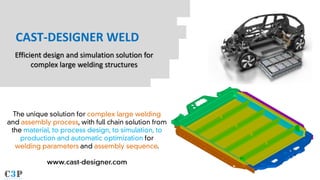
- 1. CAST-DESIGNER WELD Efficient design and simulation solution for complex large welding structures
- 2. CAST-DESIGNER | www.c3p-group.com What is Cast-Designer WELD ? CAD CAE GA/PSO DOE 02 Detects possible problems 04 Find the best operation window / best parameters 01 Existed design plan 03 Address the significant affection factors/parameters 05 Welding production
- 3. Challenge for complex large welding structures simulation Temperature Distortion Residual stress Distortion
- 4. Key technology of Cast-Designer Weld Heat source Distortion Temperature Distortion
- 5. Application: E-Vehicle battery frame To study the affection of different welding method to the final distortion. Base material: AlMgSi1 Welding method: All MIG MIG + FSW Welding speed: ~8mm/sec Total welding line: 70 Total welding length: ~30M 9.5cm CAD Model Weld line
- 6. Unique Mesh Technology Fully automatically mesh generation Very strong 3D hexahedron and tetrahedron mesh capability for complex geometry Support GUI mode and batch mesh mode, fully parametric, easy to re-mesh. Special treatment for CAD defects, i.e. geometry gap, overlay, intersection or unclose, face lose etc. Rich mesh options: local mesh, mark point, tin region mesh, 2D surface mesh, shell mesh, advance mesh smoothing, quality control etc. Fully automatic mesh assembly, support mixture mesh type. Bar element as weld line. CAD Mesh
- 7. E-Vehicle battery frame: Weld sequence design 1 2 3 4 1 2 3 4 Weld plan 1 Weld plan 2 Different weld sequence could be designed and simulated easily in Cast-Designer Weld. Cast-Designer Weld serves as an easy-to-use front end to perform welding assembly simulation for large structure. The physics of welding is fully treated in the same model. The user needs not be familiar with non-linear FEM simulation, only focus on the process design. Thermal cycle, change the material status, stresses, plastic strains, thermal strains, yield stress of the newly formed material and all other result related to a transient welding simulation are available.
- 8. Compare different welding process Displacement P1 P2 P3 P4 P5 P6 P7 P8 P9 -2 -1 0 1 2 0 50 100 P1 -5 -4 -3 -2 -1 0 1 0 50 100 P2 -5 -4 -3 -2 -1 0 1 0 50 100 P3 -5 -4 -3 -2 -1 0 1 0 50 100 P4 -6 -4 -2 0 2 0 50 100 -4 -3 -2 -1 0 1 0 50 100 P5 P6 -4 -3 -2 -1 0 1 0 50 100 -5 -4 -3 -2 -1 0 1 0 50 100 P7 P8 -3 -2 -1 0 1 0 50 100 P9 With Cast-Designer Weld, the user can compare the result of part distortion and stress for different welding method or parameters. From the contour and curve, the user can select the best welding process.
- 9. E-Vehicle battery frame: Detail simulation result Displacement - Z Displacement Plastic strain Displacement Residual stress
- 10. CAST-DESIGNER | www.c3p-group.com Cast-Designer Weld Solution WWW.C3P-GROUP.COM 10 3D Weld DFM Check Quotation Prepare Process design CAE Analysis Welding Production Welding Performance 1 3 4 5 6 AI-WELD: Automatic Optimization SmartWeld CAE Analysis (FEM + CFD) Material