Design of a hydrogen etching system for surface preparation of SiC wafers
•
0 likes•517 views

DOI: 10.1116/1.2244538

Recommended
More Related Content
More from Oleg Maksimov
More from Oleg Maksimov (20)
Recently uploaded
Recently uploaded (20)
Design of a hydrogen etching system for surface preparation of SiC wafers
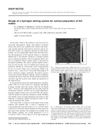
- 1. SHOP NOTES These are “how to do it” papers. They should be written and illustrated so that the reader may easily follow whatever instruction or advice is given. Design of a hydrogen etching system for surface preparation of SiC wafers D. J. Rearick, O. Maksimov,a͒ and V. D. Heydemann The Electro-Optics Center, Pennsylvania State University, 559-A Freeport Rd., Freeport, Pennsylvania 16229 ͑Received 29 March 2006; accepted 6 July 2006; published 6 September 2006͒ ͓DOI: 10.1116/1.2244538͔ Good surface finish of the substrate is the key factor for successful heteroepitaxy. Many semiconductor materials ͑GaAs, InP, and Si͒ are available from vendors with atomi- cally smooth, epiready wafer surfaces. However, silicon car- bide ͑SiC͒ wafers—an important substrate for GaN device growth—are not commercially offered with such surface fin- ish. The preparation of SiC substrate surfaces is extremely difficult due to the material’s inertness to chemical etching and its mechanical hardness. The Si-terminated ͑0001͒ sur- face of commercial silicon carbide wafers is processed by mechanical polishing. The surface typically appears defect- free on a macroscopic scale yet exhibits deep scratches and subsurface damage on a microscopic scale as demonstrated FIG. 1. Atomic force microscopy ͑AFM͒ image of a 4 ϫ 4 m2 area of a by the 4 ϫ 4 m2 atomic force microscopy ͑AFM͒ scan commercial ͑0001͒ 6H-SiC wafer diced to 1 cm2. The surface exhibits ran- shown in Fig. 1 ͑rms= 25 Å͒.1 Successful heteroepitaxy of domly oriented scratches induced by the vendor’s mechanical polish. The root mean square ͑rms͒ roughness of this surface is approximately 25 Å. device structures requires atomically flat surface terraces void of any residual subsurface damage. Surfaces exhibiting atomically flat terraces and unit cell steps promote nucleation and allow step-flow growth mode during the deposition of the epitaxial layer. It was previously shown that high-temperature annealing ͑1600– 1700 ° C͒ of SiC wafers in a hydrogen atmosphere produces virtually defect-free surface with unit cell height steps.2,3 However, such temperatures are not easily achieved in laboratory furnaces, and the cost for a high temperature, hydrogen-capable furnace will exceed $25 000. We demon- strate the design of an efficient, inexpensive ͑under $20 000͒, and reliable system for high-temperature processing of SiC substrates in hydrogen ambient and present results of SiC wafer processing in this system. The system ͑Fig. 2͒ consists of a top-loaded, water-cooled stainless steel chamber ͑Fig. 2, item 2͒ connected to a vacuum pump and a gas inlet system. A 1 ϫ 1 cm2 SiC wafer FIG. 2. Photograph of the hydrogen etcher assembly. The custom-built, is placed on a resistively heated tantalum ͑Ta͒ boat located in water-cooled cylindrical process chamber ͑2͒ is connected to the gas inlet system, the vacuum pump, and vacuum gauges. A two-color pyrometer ͑1͒ the center of the chamber. The tantalum boat available from measures substrate and heater temperature through a viewport in the center R.D. Mathis company, has overall dimensions of 4 ϫ 1 of the removable top lid. The following parts are labeled on the photograph: ϫ 0.010 in.3 with a 3 / 32 in. deep, 2.215 in. long trough and ͑1͒ Mikron M77S pyrometer with custom mounting bracket, ͑2͒ custom- built stainless steel water-cooled chamber, ͑3͒ MKS 722A 1000 Torr pres- sure transducer, and ͑4͒ MKS 253B throttle valve controlled by MKS 651C a͒ Electronic mail: maksimov@netzero.net controller. 1970 J. Vac. Sci. Technol. A 24„5…, Sep/Oct 2006 0734-2101/2006/24„5…/1970/2/$23.00 ©2006 American Vacuum Society 1970
- 2. 1971 Rearick, Maksimov, and Heydemann: Design of a hydrogen etching system for surface preparation 1971 FIG. 3. AFM image of a 4 ϫ 4 m2 area of the same ͑0001͒ 6H-SiC diced wafer shown in Fig. 1, after hydrogen etching at 1650 ° C, 650 Torr, 10% FIG. 4. AFM image of a 1 ϫ 1 m2 area of the same ͑0001͒ 6H-SiC diced H2 in 90% Ar at ϳ1100 SCCM flow for 60 min. The surface is free of wafer shown in Fig. 1, after hydrogen etching at 1650 ° C, 650 Torr, 10% H2 scratches and exhibits equally spaced unit cell height steps and terraces in 90%Ar at ϳ1100 SCCM flow for 1 h. The image shows a close-up view indicating the slight misorientation of the wafer surface against the ͑0001͒ of the steps and terraces shown in Fig. 3. The texture on the ͑0001͒ terraces basal plane. The small circular features visible on the step risers are likely is likely due to the formation of a native oxide layer in air after the hydrogen single Burgers vector threading dislocations present in the wafers, intro- etch. The root mean square ͑rms͒ roughness of this surface is approximately duced by the original SiC crystal growth process. The root mean square 2.7 Å. ͑rms͒ roughness of this surface is approximately 3.3 Å. A ͑0001͒ 6H-SiC wafer was processed under the process conditions mentioned above. Atomic force microscopy ͑AFM͒ images of 4 ϫ 4 and 1 ϫ 1 m2 areas of the processed is mechanically clamped to water-cooled current wafer are shown in Figs. 3 and 4, respectively. The surface of feedthroughs. The vacuum chamber is evacuated to a base the hydrogen etched sample is significantly smoother ͑Fig. 3, pressure of approximately 5 Torr using a Welch Vacuum rms= 3.3 Å͒ than the as-received surface that exhibited Technology 2561B dry pump. The wafer is heated to a regu- scratches ͑Fig. 1, rms= 25 Å͒. The postetch surface exhibits lated temperature of 1650 ° C by passing a dc current of equally spaced unit cell steps and terraces reflecting the 300– 350 A through the Ta boat using an Elgar Electronics slight misorientation of the wafer surface from the ͑0001͒ Power Ten 62 series 3 kW power supply ͑8 V / 350 A͒. The basal plane. Similar images and roughness have been ob- boat and wafer temperature is measured with a Mikron In- tained both at different areas of the same wafer and for wa- frared M77S two color pyrometer through a quartz viewport fers subsequently etched under the same conditions, ensuring located axially above the heater. The etching is performed for repeatability of the process with uniformity of 3.3± 0.3 A. a determined duration ͑typically 60 min͒ under horizontal The process removed approximately 3.5 m of material, cor- gas flow of ϳ1100 SCCM ͑SCCM denotes cubic centimeter responding to an etch rate of 3.5 m / h. per minute at STP͒ composed of 10% H2 in 90% Ar to en- In conclusion, we described the construction of a low- sure safe operation and stay below the hydrogen explosion cost, operator-friendly, repeatable hydrogen etching system ratio. The total pressure in the chamber is maintained at and demonstrated its capability for the preparation of defect- 650 Torr by utilizing an MKS Instruments 253B throttling free SiC wafer surfaces ready for epitaxial growth. Studies valve that is controlled by an MKS 651C pressure controller indicate that a similar hydrogen etch process can be applied connected to an MKS 722A 1000 Torr capacitive pressure to other substrates, such as GaN.4 transducer. The controller was tuned to assure constant sys- tem pressure over a range of 5 – 760 Torr, even with changes This material is based upon work supported by Dr. Colin in gas inlet rate or wafer temperature. Two 1000 SCCM Wood, ONR, under Contract No. N00014-05-1-0238. MKS M100B mass flow controllers are used to inject H2 and 1 ͑0001͒ 6H-SiC research grade wafer, Intrinsic Semiconductor. Note: Ar, respectively, and a regulated exhaust throttle valve con- Wafers from other commercial SiC vendors exhibit similar surface mor- trols the pumping speed. The custom control system is de- phology. 2 signed to assure safe, repeatable operation utilizing National V. Ramachadran, A. R. Smith, R. M. Feenstra, and D. W. Greeve, J. Vac. Sci. Technol. A 17, 1289 ͑1999͒. Instruments LABVIEW process control and data acquisition 3 K. H. Ploog, O. Brandt, R. Muralidharan, A. Thamm, and P. Waltereit, software that interfaces with the sensors, actuators, and con- J. Vac. Sci. Technol. A 18, 2290 ͑2000͒. 4 trollers. The total cost of the system is below $20 000. T. H. Myers et al., J. Cryst. Growth 246, 244 ͑2002͒. JVST A - Vacuum, Surfaces, and Films