1. (12) United States Patent
USOO7490941B2
(10) Patent No.: US 7.490,941 B2
Mintz et al. (45) Date of Patent: Feb. 17, 2009
(54) THREE-DIMENSIONAL HOLOGRAM (58) Field ofClassification Search ..................... 353/7,
DISPLAY SYSTEM 353/33, 81, 50, 122; 359/1, 14-16, 18, 23-24:
349/30: 348/719
(75) Inventors: Frederick Mintz, Chatsworth, CA (US); Seeapplication file forcomplete search history.
Tien-Hsin Chao, Valencia, CA (US);
Nevin Bryant, La Canada, CA (US); (56) References Cited
Peter Tsou, Pasadena, CA (US) U.S. PATENT DOCUMENTS
6,195,184 B1 2/2001 Chao et al. .................... 359.32
(73) Assignee: salient list ofTechnology, 6,844,948 B2 1/2005 Lieberman ................... 359,23
* cited by examiner
(*) Notice: Subject to any disclaimer, the term ofthis
patent is extended or adjusted under 35 Primary Examiner DianeI Lee
U.S.C. 154(b) by 198 days. Assistant Examiner—Magda Cruz
(74) Attorney, Agent, or Firm Tope-McKay & Associates
(21) Appl. No.: 11/216,803 (57) ABSTRACT
(22) Filed: Aug. 30, 2005 The present invention relates to a three-dimensional (3D)
(65) Prior Publication Data hologram display system. The 3D hologram display system
includes a projector device for projecting an image upon a
US 2006/O1710O8 A1 Aug. 3, 2006 display medium to form a 3D hologram.The3Dhologram is
O O formed such that a viewer can view the holographic image
Related U.S. Application Data from multiple angles up to 360 degrees. Multiple display
(60) Provisional application No. 60/605,851, filed onAug. media are described, namely a spinning diffusive screen, a
30, 2004. circular diffuser Screen, and an aerogel. The spinning diffu
sive screen utilizes spatial light modulators to control the
(51) Int. Cl. image Such that the 3D image is displayed on the rotating
GO3B 2/00 (2006.01) screen in a time-multiplexing manner. The circular diffuser
GO3B 2L/28 (2006.01) screenincludes multiple,simultaneously-operatedprojectors
GO3H IMO (2006.01) to project the image onto the circular diffuser screen from a
GO3H I/26 (2006.01) plurality of locations, thereby forming the 3D image. The
GO2B 5/32 (2006.01) aerogel can use theprojection device describedasapplicable
GO2F L/35 (2006.01) to either the spinning diffusive screen orthe circular diffuser
(52) U.S. Cl. ............................... 353/7, 353/33: 353/81; SCC.
353/50, 353/122:359/14; 35.9/15: 359/23;
34.9/30 19 Claims, 9 Drawing Sheets
500
11. US 7,490,941 B2
1.
THREE-DIMIENSIONAL HOLOGRAM
DISPLAY SYSTEM
PRIORITY CLAIM
The present application is a non-provisional patent appli
cation, claiming the benefit ofpriority of U.S. Provisional
Patent Application No. 60/605,851, filed on Aug. 30, 2004,
entitled, “Multi-Point Viewable Static and Dynamic Holo
grams.
STATEMENT OF GOVERNMENT INTEREST
The invention described herein was made in the perfor
mance ofwork under a NASA contract and is subject to the
provisionsofPublic Law96-517(35U.S.C.202)inwhichthe
Contractor has elected to retain title.
BACKGROUND OF THE INVENTION
(1)Technical Field
The present invention relates to a system for forming a
three-dimensional holographic display. More specifically, to
athree-dimensional holographic display systemthatallows a
user to view the hologram from a plurality of points and
angles, up to 360 degrees around the display.
(2) Description of RelatedArt
The world in which we live is a three-dimensional (3D)
world. However, most ofthe images created are only in two
dimensions (2D). In an attempt to improve upon traditional
images, several innovations have been conceived to more
accurately represent our 3D environment. By way of
example, 3D television shows and theme park attractions
have been created. Unfortunately, however, a viewer must
wear specialglassesto experiencethese3D images. Such 3D
image displays are achieved by simultaneously projecting
two parallax views acquired from a 3D object onto a screen.
In Such a display, viewers mustweara polarization goggleto
view the 3D images. Recently, many new technologies have
been developed that have removed the need forglasses.
3D display companies are only starting to develop proto
types for specific businesses that focus on entertainmentand
product design, but these prototypes are not practical for
general applications and average consumers. Following are
several exemplary companiesthatare developing various 3D
displays.
Actuality Systems, Inc., located at 213 Burlington Road,
Bedford, Mass. 01730, U.S.A., developed the Perspecta(R)
display. The PerspectaR) display works by projecting several
thousand 2D images per second onto a rotating screen using
Texas Instrumentsdigitalmicro-mirrordevice(DMD)chips.
Texas Instrument is locatedat 13532 N. Central Expressway,
M/S 3807, Dallas, Tex. 75243-1108, U.S.A. Similar to tele
vision, the eye fuses these images togetherto create a seam
lessimage.Theraster-scan display renders resolution, binary
images at 768x768 pixels. Each scan projects 198 images,
approximately 1.1 imagesperdegreeofrotation,and24scans
per second. The DMDs can project binary images with 5
kilohertz(kHz)speed. However, PerspectaR) displaycan only
render3-bit color(with 3 DMD chips)and limitedgray scale
images.
Deep Video Imaging, Ltd. has developed a 3D display
called Actualdepth. Deep Video Imaging, Ltd. is located at
Airport Road RD2, Mystery Creek, Hamilton, 02021, New
Zealand.Actualdepth usestwolayersofliquidcrystaldisplay
(LCD) panels to create the illusion of depth. The company
10
15
25
30
35
40
45
50
55
60
65
2
appearsto betargeting kiosks andpoint ofpurchase displays
instead of computer desktop applications, like Some ofthe
other developers.
Dimension Technologies, Inc. (DTI)has developed liquid
crystal displays (LCD’s) that display 3D images without the
need for imaging glasses. DTI is located at 315 Mt. Read
Boulevard, Rochester,N.Y. 14611, U.S.A.Thetechnical term
forDTI'stechnologyis “autostereoscopic,3Dimaging”, i.e.,
placing a single active substrate between the LCD and its
backlighter. Whenturned onitallowsthedisplayto show real
3Dimagesby creatinglightlines.Theselightlinesareplaced
behind a conventional LCD panel, creating what DTI calls a
Virtual WindowTM. The Virtual WindowTM is essentially an
LCD screen that gives the appearance ofa 3D image.
Dresden 3DGmbH, now ownedby SeeRealTechnologies,
createsa3Ddisplay onan LCDscreen. SeeRealTechnologies
islocatedat BlasewitzerStra?e43,01307Dresden,Germany.
The Dresden 3D Display (D4D) is an 18.1" thin-film transis
tor (TFT) LCD, similar to the largest Virtual WindowTM by
DTI. The D4D includes eye tracking that allows viewers to
have the freedom to view 3D images from various angles by
trackingthe location oftheirheadand changingtheaspect of
the hologram respectively. In addition to operating as a pri
mary monitor, Dresden is also marketing the D4D as a sec
ondary display that will compliment a normal monitor.
Because of this, Dresden optionally bundles a FireCL 3
graphics board with the D4D. The FireGL 3 is capable of
driving two displays simultaneously. A keyboard shortcut
allows a user to toggle the 3D display on and off when two
displays areused.Anotherfeatureofthe FireGL 3 is thatany
OpenGLprogram canbesettooutputstereo3Dimagestothe
D4D.TheFireGL3isahigh-endgraphicscardcreatedbyATI
technologies, Inc., locatedat 1 CommerceValley Drive East,
Markham, Ontario, Canada L3T 7X6.
Holografika produces the HoloVizio line of displays.
Holografika is located at Pf. 100, Budapest, H-1704, Hun
gary.The HoloViziodisplaysinclude3Dimageson amonitor
screen,allowinga viewerto walkaroundthescreen in awide
field-of-view and see the objects and shadows moving con
tinuously as in the normal perspective. Using a Holovizio
display, itis possible seebehindobjects; whilehidden details
appear, others disappear (motion parallax). The displays are
currently available in 32" (16:9)and 26" (4:3) screen sizes.
LightSpace Technologies, Inc. produces the DepthCube
Z10243D display. LightSpace Technologies, Inc. is located
at26PearlStreet, Norwalk, Conn. 06850, U.S.A.TheDepth
Cube Z10243D display consists of20 stacked LCD shutter
panels, with video projected through the LCD shutters,
thereby allowing viewers to see objects in three dimensions
without the need for glasses. Unlike auto-stereoscopic dis
plays, DepthCubetechnology doesn’tlimit thefield-of-view,
allowing multiple people to experience the 3D effect simul
taneously.
Theabovetechniquesstillhaveproblems. Forexample,the
Actuality PerspectaR) display has very limitedcolorandgray
scales,limitingthedisplaytoshow simpleimagesonly. Addi
tionally, none ofthecurrently available techniques allow for
walk around displays.
Thus, a needexistsin theartfora 3D display thatallowsa
viewer to walk 360 degrees around the display and see a life
size or reduced, 3D volumetric image in real-time.
SUMMARY OF THE INVENTION
The present invention describes a three-dimensional (3D)
hologram display system. The 3D hologram display system
comprises a projector device configuredto projectan image,
12. US 7,490,941 B2
3
and a display medium for displaying the image from the
projector device as a holographic image. Such that a viewer
can view the holographic image from multiple view points.
When the holographic image is projected upon the display
medium, a viewer can view different aspects of the holo
graphic image from different angles.
In another aspect, the projector device further comprises
multiple, simultaneously-operable projectors for projecting
image components. Each image component is one halfofa 10
Stereo image. Such that when two corresponding halves ofa
Stereo image convergeupon thedisplay medium,they form a
full Stereogram.
In anotheraspect, the present invention further comprises
an image formation mechanism for redirecting the image
componentsontothedisplay mediumtoformtheholographic
image.
15
In yet another aspect, the image formation mechanism is
selectedfromagroupconsistingofmultiplerefractingprisms
and multiple reflecting mirrors.
In another aspect, the display medium is selected from a
group consisting ofa circular diffuser screen, and aerogel.
Additionally,theimageformation mechanism is formedin 25
aring-shape suchthatthe imagecomponents canbereflected
to the interior ofthe display medium.
In anotheraspect, each multiple, simultaneously-operable
projectorispositionedsuch thateachhalfofthe stereoimage so
is refracted/reflected by every other prism or mirror in the
image formation mechanism to converge upon the display
medium and form the holographic image.
Inanotheraspect,thepresent inventionfurthercomprisesa
processorconfiguredforprocessingtheimageandpresenting
the image to the projector device to be projected as a 3D
hologram onto the display medium.
35
In yet another aspect, the projector device is positioned
Such that it is within the ring-shape ofthe image formation 40
mechanism.
In another aspect, the projector device is formed in a cir
cular mounting frame Suchthatitsurrounds the ring-shape of
the image formation mechanism. 45
In another aspect, the projector device further includes:
three grayscale spatial light modulators (SLM) that are used
to display red, green, and blue (RGB) data separately, where
the RGB data is received from a graphic 3D data processor;
three red, green, and blue light sources to illuminate each so
SLM with three beams; anachromatic, optics light ray com
binertocombinethethreebeamstobecomeacollinearbeam;
and an input lens forpassing the collinearbeam through the
input lens to illuminate the display medium.
Furthermore, the display medium isselected fromagroup SS
consisting ofa spinning diffusive screen and aerogel.
Finally,as can be appreciatedby one in theart, thepresent
invention is not limited to the 3D hologram system, but also
includes a method and computer program product for form
ing Such ahologram and system. The method comprises acts
offorming each ofthe respective parts ofthe 3D hologram
display system herein such that they form the 3D image.
Additionally, the computerprogram product comprises com
puter-readable instruction means stored on a computerread- 65
able medium forcausinga computerto processan imageand
project the image as a 3D image. The computer program
60
4
product is further configured to operate the respective por
tions of the 3D hologram display system according to the
present invention.
BRIEF DESCRIPTION OF THE DRAWINGS
The objects, features and advantages ofthe present inven
tion willbeapparentfrom thefollowingdetailed descriptions
ofthepreferredaspects ofthe invention taken in conjunction
with reference to the following drawings, where:
FIG. 1 illustrates a component diagram depicting compo
nents ofa three-dimensional (3D) hologram display system
according to the present invention;
FIG.2illustratesadiagram ofacomputerprogram product
according to the present invention;
FIG.3 is an illustration ofsystem schematic ofa 3Dholo
gram display system according to the present invention,
where a spinning diffusive screen is used to display a 3D
image;
FIG.4isan illustrationofspinningdiffusivescreenaccord
ing to the present invention;
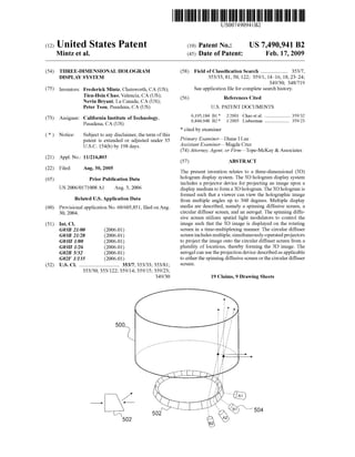
FIG. 5 is an illustration ofa 3D hologram display system
according to the present invention, where a circular diffuser
screen is used to display the 3D image:
FIG. 6A is an illustration ofan exemplary assembly order
ofSuccessive refractor/reflector pairs (i.e., image formation
mechanism) which match the displacement of a projector
device array;
FIG. 6B is an illustration ofan exemplary convergence of
therefractedorreflectedimages(i.e.,halfofthestereoimage)
onto the circular diffuser screen to form a full stereogram
(hologram);
FIG. 7is an illustration ofthe3Dhologram display system
according to the present invention, where the image forma
tion mechanism is depicted as a prism;
FIG. 8is an illustration ofthe3Dhologram display system
according to the present invention, where the image forma
tion mechanism is depicted as a reflective device; and
FIG. 9 is an illustration ofanother aspect ofthe 3D holo
gram display system,wherethedisplay medium is an aerogel
material.
DETAILED DESCRIPTION
The present invention relates to a system for forming a
three-dimensional holographic display. More specifically, to
athree-dimensionalholographic display systemthatallows a
user to view the hologram from a plurality of points and
angles, up to 360 degrees around the display. The following
description is presented to enableone ofordinary skill in the
art to make and use the invention and to incorporate it in the
context of particular applications. Various modifications, as
well as a variety of uses in different applications will be
readily apparent to those skilled in the art, and the general
principles defined herein may be applied to a wide range of
embodiments. Thus, the present invention is not intended to
belimitedtotheembodimentspresented,butistobeaccorded
the widest scope consistent with the principles and novel
features disclosed herein.
In the following detailed description, numerous specific
details are set forth in order to provide a more thorough
understanding ofthe present invention. However, it will be
apparent to one skilled in the art that the present invention
may be practiced without necessarily being limited to these
specificdetails. In otherinstances,well-known structuresand
devices are shown in block diagram form, rather than in
detail, in orderto avoid obscuring the present invention.
13. US 7,490,941 B2
5
The reader's attention is directed to all papers and docu
mentswhichare filedconcurrentlywiththisspecificationand
which are open to public inspection with this specification,
and the contents ofall such papers and documents are incor
poratedherein by reference. All the features disclosed in this
specification, (including any accompanying claims, abstract,
anddrawings) maybereplacedbyalternativefeaturesserving
the same, equivalent or similar purpose, unless expressly
stated otherwise. Thus, unless expressly stated otherwise,
each featuredisclosedisoneexampleonly ofageneric series
ofequivalent or similar features.
Furthermore, any element in a claim that does not explic
itly state “means for performing a specified function, or
“step for performing a specific function, is not to be inter
pretedas a “means”or“step’clauseas specified in 35 U.S.C.
Section 112, Paragraph 6. Inparticular, theuseof“stepof or
“act of in the claims herein is not intended to invoke the
provisions of35 U.S.C. 112, Paragraph 6.
Beforedescribingtheinvention in detail, firsta glossaryof
terms used in the description and claims is given as a central
resource for the reader. Next, a description ofvarious princi
pal aspects of the present invention is provided. Third, an
introduction is provided to provide the reader with a general
understanding ofthepresentinvention. Finally, a description
ofvariousaspects ofthepresentinvention is provided togive
an understanding ofthe specific details.
(1) Glossary
Beforedescribing the specific details ofthepresent inven
tion,aglossaryisprovidedinwhich varioustermsusedherein
and in the claims are defined. The glossary is intended to
provide the reader with a general understanding for the
intended meaningofthe terms, but is not intended to convey
theentireScopeofeach term. Rather,theglossary isintended
to Supplement the restofthe specification in more accurately
explaining the terms used.
Aerogel The term “aerogel refers to a silicon-based
Solid with a porous, Sponge-like structure in which approxi
mately 99.8 percent ofthe volume is empty space.
Instruction Means—The term “instruction means' as used
with respect to this invention generally indicates a set of
operations tobeperformedon acomputer,and may represent
pieces ofa wholeprogram orindividual, separable, Software
modules. Non-limiting examples of “instruction means'
include computer program code (source or object code) and
“hard-coded electronics (i.e. computer operations coded
intoacomputerchip).The“instruction means' maybestored
in the memory of a computer or on a computer readable
medium such as a floppy disk, a CD-ROM, and a flash drive.
Multiple Viewpoints. The term “multiple viewpoints'
refers to the view-abilityofan image thatis notflatandthat is
viewable from a plurality of points and angles, up to and
including 360 degrees ofviewing.
Spatial Light Modulator Theterm“spatial light modula
tor (SLM)' refers to an array ofoptical elements (pixels) in
which each pixel acts independently as an optical “valve' to
adjust or modulate light intensity.
(2) Principal Aspects
The present invention has three “principal aspects. The
first is a three-dimensional (3D) hologram system. The 3D
hologram system is typically in the form ofa computer sys
tem operating software or in the form of a “hard-coded
instruction setthatisconfiguredtooperateadevicecapableof
projecting and displaying a 3D holographic image. The 3D
hologram system also includes the corresponding projection
anddisplay devices. The secondprincipalaspect isa method,
typically in the form ofSoftware, operated using a data pro
cessingsystem (computer).The method also includes acts of
10
15
25
30
35
40
45
50
55
60
65
6
forming the 3D hologram display system described herein.
Thethirdprincipalaspectisa computerprogramproduct.The
computer program product generally represents computer
readable codestoredon a computerreadable medium such as
an optical storagedevice, e.g.,a compact disc (CD) ordigital
Versatile disc (DVD), ora magnetic storage device such as a
floppydiskormagnetictape.Other, non-limitingexamples of
computer readable media include hard disks, read-only
memory (ROM), andflash-typememories.Theseaspects will
be described in more detail below.
A block diagram depicting the components of a three
dimensional (3D)hologram system 100 ofthepresent inven
tion isprovidedin FIG.1. The3Dhologram system is usedto
control the system and to display the image sequence. The
hardware system implementation requires precision optics,
high speed datatransferand large display memory, as well as
otherenhancements.The3Dhologramsystem 100comprises
an input 102 for receivingan imageto process andproject as
a 3D image. Note that the input 102 may include multiple
"ports.” An output 104 is connected with the processor for
providing signals to at least one projector 109 forprojecting
the imageas a3Dhologram ontoa display medium 110 (e.g.,
diffuser screen or aerogel). Output may also be provided to
other devices or otherprograms; e.g., to otherSoftware mod
ules, forusetherein.Theinput102andtheoutput104areboth
coupled with a processor 106, which may be a general-pur
posecomputerprocessor oraspecializedprocessordesigned
specifically for use with the present invention (i.e., a 3D
graphics processor). The processor 106 is coupled with a
memory 108 to permit storage of data and software to be
manipulated by commands to the processor.
An illustrative diagram of a computer program product
embodying the present invention is depicted in FIG. 2. The
computerprogram product 200 is depicted as an optical disk
suchasaCDorDVD. However,as mentionedpreviously,the
computer program product generally represents computer
readable code stored on any compatible computer readable
medium. The computer program product is configured to
perform the operations ofprocessing and projecting the 3D
hologram as described herein.
(3) Introduction
The present invention discloses a new approach to the
display of holograms which can be viewed either with or
without Stereo glasses in a configuration which allows the
viewer to walk around the display, viewing different aspects
of the same three dimensional (3D) models or original
objects, taken by multiple stereoscopic cameras orgenerated
byothermeans. Alternatively, multiple viewers may view the
different aspects of the same original or the same aspect
(view) at the same time.
In one aspect, the present invention uses multiple, simul
taneous, Stereoprojections, the images ofwhichareoptically
formed by multiple refracting prisms or reflecting mirrors
(i.e., image formation mechanism), such that the images are
formed and visually justified or accurately displayed on a
diffuser Screen (e.g., circular diffuser screen), which is
located in appropriate locations, such as abovetheprojector
refractor/reflector array So as to allow space for the equip
ment.Additionally,theimage can be displayed on an aerogel
that allows for 3D walk-around viewing. In another aspect,
the image is formed using spatial light modulators and is
projected onto a flat, rotating diffusive screen.
3Ddisplaysareachievedbyprojecteddata,eithercollected
from Stereo imaging cameras or from computer simulation.
The display techniques can be classified into two categories:
1) Using a CRT or LCD monitor to project two angularly
separated images (each from one oftwo stereo cameras or
14. US 7,490,941 B2
7
from a simulated database) into the viewer's eye, and as
applicable to the present invention, 2) Graphic rendering the
Stereoinputanduseittocontrola "spatiallight modulator” or
lightScannerprojectedontoadisplay medium.Asaresult,3D
imagescanbeperceivedinspace.Theviewercanperceivethe
same 3D image from any angle without having to wear spe
cial goggles. The perceived 3D does not have parallax since
the Source ofthe3D data came from the stereo imaging type
ofinput.
(4) Description ofVarious Aspects
As touched upon above and described in further detail
below, the present invention includes three types ofdisplay
media for reflecting and displaying the 3D image. The first
beingaspinningdiffusivescreen,whereanimageisprojected
onto the Surface of a spinning diffusive screen in a time
multiplexing manner. The second display medium is a circu
lar diffuser screen, where images are projected onto the Sur
face of the circular diffuser screen, while the third is an
aerogel material, where images areprojectedinto theaerogel
material to form the 3D image.
(4.1) Spinning Diffusive Screen
Thesystem schematicdiagram ofthe3Dhologram system
300usingaspinningdiffusivescreen (i.e.,display medium)is
shown in FIG. 3. A projector device 301 is used to project a
holographic imageontothedisplay medium 303.Theprojec
tor device 301 includes three grayscale spatial light modula
tors (SLM) 302 that are used to display red 304, green, 306,
and blue 308 (RGB) data separately. Three red, green and
blue lightsources (i.e., laserorlightemittingdiodes (LEDs))
310 will illuminateeach SLM. The threebeamsarecombined
by an achromatic, optics light ray combiner 312 to become
collinear. The three SLMs will be driven by data from a
graphic3Ddataprocessor314.Thethroughputlightrayspass
through an input lens 316 to illuminate the display medium
3O3.
In this aspect andas shown in FIG. 4, the display medium
303 is a rotating diffusive screen 400 placed at the output
imagingplane. Inthisaspect,therotatingdiffusivescreen400
is poweredby a motor402 to rotate thescreen 400 ata speed
thatis appropriateto reflectanddisplayan image.Thus, a3D
image can be displayed on the rotating screen 400, inatime
multiplexing manner.
Anadvantageofthearchitectureofthepresentinventionis
the data throughput rate. The present invention utilizes a
spatial light modulator,Suchas thatrecently developedby Jet
Propulsion Laboratories (JPL) and the Boulder Nonlinear
Systems (BNS), with high-speed (up to 4 kHz)andgrayscale
(8-bits insteadofbinary) capability that is farsuperior to the
Deformable Mirror Device (DMD) being used by the Actu
ality Devicesystem. JPLislocatedat 4800OakGrove Drive,
Pasadena, Calif. 91109, U.S.A. BNS is locatedat450 Court
ney Way, #107, Lafayette,Colo. 80026, U.S.A. Additionally,
software development tools are used that convertgeneral 3D
models to intercept OpenGL data and effectively slice it for
display across the screen panels. Forexample, Such 3D soft
ware development tools include a 3D volume display appli
cation programming interface (API)/toolkit, a Volumetric
rendering algorithm, and a3D volume memory format man
agement program.
(4.2) Circular Diffuser Screen
Another aspect of the present invention uses a circular
diffuser screen as the display medium.As shown in FIG. 5, a
circular diffuser screen 500 is used to display the 3D image.
As can be appreciated by one skilled in the art, there are
numerous methods and techniques for forming a circular
diffuser screen 500 capable of displaying an image. For
example, a flat sheet ofdiffuser material is bent around to
10
15
25
30
35
40
45
50
55
60
65
8
form a column. The dimensions ofthe column are delimited
by currentmanufacturingspecificationsandend-useapplica
tions.Theendsofthesheetarejoinedtoformaseamlessjoint
So as not to distort the image projected at the diffuser Screen
atthat spot.A non-limitingexampleofsuch diffusermaterial
is that made by Physical Optics Corp. Physical Optics Corp.
is located at20600Gramercy Place, Building 100,Torrance,
Calif. 90501-1821, U.S.A.
As shown in FIG. 5,an image formation mechanism502 is
included and shapedin Such a way as to take parallel lines of
light or otherwise normal images and re-form them onto the
circular diffuser screen 500, such that the original image
appearsnormalandfullyjustifiedasthedisplayedimage.The
image formation mechanism502 is eithera reflecting surface
or a refracting prism, depending upon which direction the
image is projected from and upon the diffuser screen 500.
For example, ifthe image input is from the opposite side,
then the image formation mechanism 502 becomes a reflect
ing mirror. Ineithercase,theimageisformedandprojectedin
Sucha way thatafullyjustified imageappears onthediffuser
Screen 500.
Also as shown in FIG. 5, the image formation mechanism
502 may include a plurality of refractors or reflectors,
mounted ina circleSuch that multipleimages aretransmitted
onto the circular diffuser screen 500 by a projector device
504. The projector devices 504 are ordered in a circular
mounting frame Such that each stereo image is refracted/
reflected by every other prism or mirror in the ring-shaped
image formation mechanism 502.The projector devices 504
are any suitable projection mechanism or device forproject
ing an image.
Ifa succession ofstereo images, taken by a succession of
Stereocameras, in order,areprojectedto theimageformation
mechanism 502 and thereafter onto the circular diffuser
screen 500, then a 360° (a true rendering) of the original
imagewill be shown on the screen 500. Ifviewerswish tosee
the sameaspect(angular view) ofthe original object, then all
projectordevices 504 can be used to project the same image
simultaneously.
Use ofthecirculardiffuserscreen 500 relies on projecting
each halfofa stereo image onto the imageformation mecha
nism502,withthetwohalvescomingtogetheronthecircular
diffuser screen 500. As shown in FIG. 5, a plurality ofpro
jector devices 504 (e.g., video projectors) are mounted side
by side, in alternate order, to project image components. In
other words, thefirst-stereo-half(e.g., thelefthalf)ofthefirst
aspect (angular view) ofan object is projected by Projector
A1, while the right-stereo-halfofthe first aspectofthat view
will be projected by ProjectorA2, and so forth. Each stereo
pairisprojectedbyalternatingstereoprojectordevices504 so
as to produce a hologram onto the circular diffuser Screen
500. Ifnecessary, uniform microsecond delays can be intro
duced to the system ifstereo glasses are to be used for view
1ng.
Although described herein as being mounted in alternate
order, one skilled in the art can appreciate that the present
invention is not intended to be limited thereto, as there are
other configurations to createa space between each halfofa
Stereo image.
FIG. 6A is an illustration ofan exemplary assembly order
ofeach Successive refractor/reflectorpair (i.e., image forma
tion mechanism 502) which matches the displacementofthe
projector device 504 array. The interpupillary displacement
of human eyes is approximately 7.0 centimeters. In one
aspect, it is useful to take advantage ofthis natural parallax
system in the design ofthe3Dhologram display system. For
example, the placement of stereo cameras, projectors, and
15. US 7,490,941 B2
refractor/reflectorsand/ortheuseofimagedelay mechanisms
maybeadjustedtoaccountforthe naturalparallaxsystem.As
a specific example, thedistance between each corresponding
refractor/reflector (e.g., A1 and A2) in the image formation
mechanism 502 may be approximately 7.0 centimeters.
As discussed above, two halves of a stereo image (each
being one halfof a stereo image 600) are projected to the
image formation mechanism 502, which then directs each
halfof the stereo image 600 to converge onto the circular
diffuser screen.
FIG. 6B is an illustration ofan exemplary convergence of
therefractedorreflectedimages (i.e.,halfofthestereoimage)
onto thecirculardiffuserscreen500 to formafullstereogram
(hologram) 602. As can be appreciated by one skilled in the
art, once the hologram is formed, it may be viewed from
multiple positions and angles, thereby forming a truly 3D
hologram.
AsshowninFIGS.7and8,theprojectordevice504 maybe
mounted inside or outside the image formation mechanism
502,dependingontheparticularconfiguration.Alsoshownin
FIGS. 7 and 8, the image formation mechanism 502 is either
aprism array orreflectorarray, dependingupon which direc
tion the image is being projected from and upon the circular
diffuser screen 500, and upon the particularapplication.
Note that the Stereo images may either be conjugated or
delayed depending on the type of viewing desired by the
application. Ifawide view ofthehologram is necessary,then
Stereo glasses are used. Ifa single viewer for each aspect of
the hologram is desired, then a conjugated display will be
chosen.
Inordertoprojectanumberofstatic ordynamic 3Dimages
at a suitable display matrix which can be viewed from any
angle on a singleplane, the angle 0 depends on the pitch (LS
Pitch) ofthe projector lenses (on the projector device), the
focal depth (Rlfocus) and the index ofrefraction (N=?). The
index ofrefraction is dependent upon the angle ofrefraction
0.
The horizontal viewing pitch (FPPitch) on the x,y, plane
willbeslightly largerthanthatoftheprojectorlens such that:
RL.f.
FPitch = Ls. ' '
Dobs
Dobs denotes the optimal distance ofthe display from the
observers’ eyes. The number ofviews Nview is distributed
over the viewing plane Such that the viewing density at the
observers distance Dobs is expressed as:
2(Dobs)(tane)
is
Nviews
For Nview=100, this density step isVD. The viewingden
sity VD is 20=19°. Thus the possible number of views
Nview=100.
(4.3)Aerogel Material
In another aspect and as shown in FIG. 9, the display
medium isanaerogel material900.Aerogel is a silicon-based
Solid with a porous, Sponge-like structure in which approxi
mately 99.8 percent of the volume is empty space. Due to
having Such a small density, Aerogel has a hazy, Smoke-like
appearance. However, enough solid exists to refract light,
thereby creating a display medium that is capable ofrefract
ing and displaying a 3D image. Aerogel was invented by the
National Aeronautics and Space Administration (NASA) as
10
15
25
30
35
40
45
50
55
60
65
10
an insulation material and is now produced by a few compa
nies, suchasAspenAerogels. NASAislocatedatSuite 1M32,
Washington, D.C. 20546-0001, U.S.A. Aspen Aerogels is
located at 30 Forbes Road, Northborough, Mass. O1532,
U.S.A.
Aerogel is very delicateand Subjectto breakage. To main
tain its structure, theaerogel is contained within a column or
other container-like structure. The Stereoscopic images are
then projected into the aerogel to form the 3D hologram.
Using a projection system similar to that described above
regarding the circulardiffuserscreen,aplurality ofprojector
devices 504 can be used to project halves ofa stereo image
onto an image formation mechanism 502. The image forma
tion mechanism 502 is used to redirect the image into the
aerogel Such that the halves ofthe stereo image converge in
the aerogel as a hologram (full stereogram).
In another aspect (not shown), the holographic image is
projected into the aerogel using the projector device
described above regarding the spinning diffusive Screen.
What is claimed is:
1.Athree-dimensionalhologram displaysystem,compris
1ng:
a projector device comprising multiple, simultaneously
operable projectors for projecting image components,
where each image component is one half of a stereo
image. Such that when two corresponding halves of a
stereo image converge upon the display medium, they
form a full Stereogram;
a display medium for displaying an image from the pro
jectordeviceas aholographic image. Such thata viewer
can view the holographic image from multiple view
points, whereby when the holographic image is pro
jected upon the display medium, a viewer can view
differentaspectsoftheholographicimagefrom different
angles.
2. A three-dimensional hologram display system as set
forth in claim 1, further comprising an image formation
mechanism for redirecting the image components onto the
display medium to form the holographic image.
3. A three-dimensional hologram display system as set
forth in claim 2, wherein the image formation mechanism is
selectedfromagroupconsistingofmultiplerefractingprisms
and multiple reflecting mirrors.
4. A three-dimensional hologram display system as set
forth in claim3,whereinthedisplay medium is selected from
a group consisting ofa circular diffuser Screen, and aerogel.
5. A three-dimensional hologram display system as set
forth in claim 4, wherein the image formation mechanism is
formedinaring-shapesuchthattheimagecomponentscanbe
reflected to the interior ofthe display medium.
6. A three-dimensional hologram display system as set
forth in claim 5, wherein each multiple, simultaneously-op
erableprojectorispositionedsuch thateach halfofthe stereo
image is refracted/reflectedby every otherprism or mirrorin
theimageformation mechanismto convergeuponthedisplay
medium and form the holographic image.
7. A three-dimensional hologram display system as set
forthinclaim 6,furthercomprisingaprocessorconfiguredfor
processing the imageand presentingthe imagetotheprojec
tor device to be projectedas a 3D hologram onto the display
medium.
8. A three-dimensional hologram display system as set
forth in claim 7, wherein the projector device is positioned
Such that it is within the ring-shape ofthe image formation
mechanism.
9. A three-dimensional hologram display system as set
forth in claim 7, where the projector device is formed in a
16. US 7,490,941 B2
11
circularmounting frameSuchthatitsurroundsthering-shape
ofthe image formation mechanism.
10. A three-dimensional hologram display system as set
forth in claim 1, wherein the projector device further
includes:
three grayscale spatial light modulators (SLM) that are
used to display red, green, and blue (RGB) data sepa
rately,wheretheRGBdataisreceivedfromagraphic3D
data processor,
three red, green, and blue light sources to illuminate each
SLM with three beams:
an achromatic, optics light ray combiner to combine the
three beams to become a collinearbeam; and
an input lens for passing the collinear beam through the
input lens to illuminate the display medium.
11. A three-dimensional hologram display system as set
forth in claim 10, wherein the display medium is selected
from a group consisting of a spinning diffusive screen and
aerogel.
12. A three-dimensional hologram display system as set
forth in claim 1, further comprising an image formation
mechanism for redirecting the image onto the display
medium to form the holographic image.
13. A three-dimensional hologram display system as set
forth in claim 12, whereintheimage formation mechanism is
selectedfromagroupconsistingofmultiplerefractingprisms
and multiple reflecting mirrors.
5
10
15
25
12
14. A three-dimensional hologram display system as set
forth in claim 12, whereintheimage formation mechanism is
formedin aring-shape Suchthattheimagecanbe reflectedto
the interior ofthe display medium.
15. A three-dimensional hologram display system as set
forth in claim 14, where the projector device is formed in a
circularmounting frame Suchthat itSurroundsthering-shape
ofthe image formation mechanism.
16. A three-dimensional hologram display system as set
forth in claim 12, wherein the projector device is positioned
Such that it is within the ring-shape ofthe image formation
mechanism.
17. A three-dimensional hologram display system as set
forth in claim 1, wherein each multiple, simultaneously-op
erableprojectorispositionedsuch thateach halfofthe stereo
image is refracted/reflectedby every otherprism or mirrorin
theimageformation mechanismto convergeuponthedisplay
medium and form the holographic image.
18. A three-dimensional hologram display system as set
forth in claim 1,whereinthedisplay medium is selected from
a group consisting ofa spinning diffusive screen, a circular
diffuser Screen, and aerogel.
19. A three-dimensional hologram display system as set
forthinclaim 1,furthercomprisingaprocessorconfiguredfor
processing the imageand presentingthe imagetotheprojec
tor device to be projectedas a 3D hologram onto the display
medium.