Thông số kĩ thuật mitsubishi thiet bi dien mcb
•
0 likes•256 views

Catalogue mitsubishi thiet bi dien mcb

Recommended
More Related Content
Viewers also liked
Viewers also liked (16)
Similar to Thông số kĩ thuật mitsubishi thiet bi dien mcb
Similar to Thông số kĩ thuật mitsubishi thiet bi dien mcb (20)
More from Công ty cổ phần OKS | Tổng thầu thi công Nhà máy GMP, Tổng thầu thi công Nhà kho GSP
More from Công ty cổ phần OKS | Tổng thầu thi công Nhà máy GMP, Tổng thầu thi công Nhà kho GSP (20)
Recently uploaded
Recently uploaded (20)
Thông số kĩ thuật mitsubishi thiet bi dien mcb
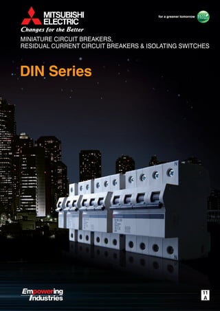
- 1. DIN Series 11 MINIATURE CIRCUIT BREAKERS, RESIDUAL CURRENT CIRCUIT BREAKERS & ISOLATING SWITCHES
- 2. High-quality, high-performance circuit breakers suitable for household electrical distribution panels I n t r o d u c i n g t h e D I N S e r i e s … 1
- 3. I N D E X Features, Product Line-up and Points to Note 3 Features and Product Line-up Points to Note 3 4 Specifications 5-6 Ordering Information 14 2 Characteristics and Dimensions 9 Miniature Circuit Breakers (MCB) Residual Current Circuit Breakers (RCCB) Residual Current Circuit Breakers with Overcurrent Protection (RCBO) Isolating Switches 9-10 11 12 13 Accessories 7-8
- 4. Features Product Line-up Explanation of Markings (Example Model Type : BH-D6) (1) All models fully comply with IEC regulations (2) Units can be mounted on a standard 35mm IEC rail (3) Residual current circuit breakers use an original Mitsubishi Electric IC securing reliable earth-leakage protection (4) High current-limiting performance (5) Compliance with IP2X protection rating (6) All models are compatible with reverse connection (7) DC circuit-compatible model (BH-D10) added to product line-up MCB RCCB RCBO Isolating Switch BH-D6 BH-D10 BH-D10 (For DC) BH-DN BV-D BV-DN KB-D Model type 1, 2, 3, 4(3+N) 1+N 1, 2, 3, 4(3+N) 1 2 1+N 2(1+N), 4(3+N) 1+N 1, 2, 3, 4(3+N) No of poles (P) 0.5∼63A 0.5∼40A 0.5∼63A 0.5∼63A 6∼20A 25, 40, 63A 6∼40A 32, 63, 80A Rating TYPE B, C, D TYPE B, C TYPE B, C, D TYPE B, C TYPE C - TYPE C - Instantaneous tripping 230/400AC 230AC 230/400AC 125DC 250DC 230AC 230/400AC 230AC 230/400AC Voltage (V) 6 10 10 4.5 - 4.5 - Short-Circuit capacity (kA) IEC60898-1 IEC60898-1 IEC60898-2 IEC60898-1 IEC61008 IEC61009 IEC60947-3 Compliance standard Technical Specifications Ambient temperature range Frequency -10 ~ +40℃ 50/60Hz 3 Model type Rated voltage Standard Short-circuit capacity Instantaneous tripping model type and Rated current Wiring diagram
- 5. 1. Installation 2. Removal Points to Note DIN Series MINIATURE CIRCUIT BREAKERS,RESIDUAL CURRENT CIRCUIT BREAKERS & ISOLATING SWITCHES 4 Installation Standard IEC35mm rail installation is possible. Fix by attaching a slip stopper. Connection At the time of wire connection, fasten the terminal screws with the torque stated in the table below. Fig-1 Fastening torque Screw diameter Fastening torque (N・m) Model type BH-D6, BH-D10, BV-D, KB-D SHTA400-05DLS, SHTD048-05DLS BH-DN, BV-DN AL-05DLS, AX-05DLS, ALAX-05DLS AX2-05DLS M5 M4 M3.5 1.7∼2.5 1.0∼1.5 0.8∼1.0 ①Off Move the handle up/down to turn power On/Off. Tripping operation refers to automatic opening (breaking) of circuits. Earth-leakage Test (1) Installation (2) Removal Earth-leakage test steps: (1) Move the handle to the On position under rated voltage. (2) Push the yellow test button. (3) At this time, the RCCB or RCBO must be tripped within the specified time. (4) The handle will move to the Off position. (5) The earth-leakage indication changes from white to red. 1 2 4 Opening, Closing and Tripping Operations 3 Withstand Voltage Test 5 Installation of Accessories (AX, AL, SHT) 6 Measuring position Test Handle position Between different poles Between main circuit live part and ground On line side On load side BV-D 2P BV-DN BV-D 4P BV-D 2P BV-DN BV-D 4P Between right pole (terminal symbol 6) and N pole Between poles other than above Between right pole (terminal symbol 6) and N pole Between poles other than above Between terminals on line side and load side Insulation resistance measurement Withstand voltage test ON ○ ▲ ▲ ○ ▲ ▲ ○ ー OFF ○ ○ ○ ○ ▲ ▲ ○ ○ ON ○ × × ○ × × ○ ー OFF ○ ○ ○ ○ × × ○ ○ Withstand voltage test: The voltage applied to the main circuit during the withstand voltage test is 2,000VAC (effective for 1min). Do not conduct a withstand voltage tests using voltages exceeding 2,000VAC. Measurement of insulation resistance and withstand voltage test Please note the following restrictions (① and ② below) that apply when using earth-leakage circuit breakers. Measuring insulation resistance: - Do not use a 1000V insulation resistance tester. Please use a 500V insulation resistance tester. - The “▲” marks in the table are based on minimum insulation resistance values. Testing withstand voltage: The “X” marks in the table below indicate that the test voltage is not to be applied to that model. (If a test voltage is accidently applied to one of these models, do not reuse the product regardless of whether or not they were tripped.) (1) (2) ① ② ②Hook ③Insert ④Click ② ①
- 6. 5 MCB Type BH-D6 BH-D10 BH-DN Image No. of poles [P] 1 2 3 4(3+N)∗1 2(1+N)∗1 1 2 3 4(3+N)∗1 2 (1+N)∗1 Instantaneous tripping Type B, C, D∗2 Type B, C∗2 Type B, C, D∗2 Type C∗2 Rated insulation voltage Ui [V] 440 440 230 Rated current In [A] at ambient temperature 30: 0.5, 1, 1.6, 2, 3, 4, 6, 10, 13, 16, 20, 25, 32, 40, 50, 63 0.5,1,1.6, 2, 3, 4, 6,10, 13,16, 20, 25, 32, 40 0.5, 1, 1.6, 2, 3, 4, 6, 10, 13, 16, 20, 25, 32, 40, 50, 63 6, 10, 16, 20 Rated short- circuit capacity [kA] IEC60898-1 GB10963.1 (Icn) AC 230V 6 – 6 10 – 4.5 230/400V 6 – – 10 – – 400V – 6 – – 10 – Number of operating cycles Without current 8,000 10,000 20,000 With current 8,000 10,000 20,000 Dimensions [mm] a 18 36 54 72 36 18 36 54 72 18 b 87 87 88 c 44 44 44 ca 70 70 70 Type of overcurrent release Thermal-magnetic Thermal-magnetic Thermal-magnetic Mounting IEC35mm rail IEC35mm rail IEC35mm rail Applicable wire size 1 to 25mm2 1 to 25mm2 1 to 10mm2 Weight [kg] 0.15 0.3 0.45 0.55 0.25 0.15 0.3 0.45 0.55 0.12 Accessories (optional) Alarm switch (AL) – Auxiliary switch (AX) – Shunt trip (SHT) – Terminal connection Solderless Solderless Solderless Based on standard IEC60898-1 IEC60898-1 IEC60898-1 CE marking EN60898-1 : Self-declaration EN60898-1 : Self-declaration EN60898-1 : Self-declaration CCC GB10963.1 GB10963.1 GB10963.1 ∗1: N pole is a switched neutral pole (without overcurrent release device). ∗2: Type B: (3 In <, 5 In), Type C: (5 In <, 10 In), Type D: (10 In <, 20 In) Specifications a ca c b For DC Type BH-D10 Image No. of poles [P] 1 2 Instantaneous tripping Type B, C∗3 Rated insulation voltage Ui [V] 250 Rated current In [A] at ambient temperature 30: 0.5, 1, 1.6, 2, 3, 4, 6, 10, 13, 16, 20, 25, 32, 40, 50, 63 Rated short- circuit capacity [kA] IEC60898-2 GB10963.2 (Icn) DC 125V 10 – 250V – 10 Number of operating cycles Without current 8,000 With current 4,000 Dimensions [mm] a 18 36 b 87 c 44 ca 70 Type of overcurrent release Thermal-magnetic Mounting IEC35mm rail Applicable wire size 1 to 25mm2 Weight [kg] 0.15 0.3 Accessories (optional) Alarm switch (AL) Auxiliary switch (AX) Shunt trip (SHT) Terminal connection Solderless Based on standard IEC60898-2 CE marking EN60898-2 : Self-declaration CCC GB10963.2 ∗3: Type B: (5 In <, 7 In), Type C: (7 In <, 15 In) a ca c b
- 7. DIN SeriesDIN Series 6 Specifications Isolating switch Type KB-D Image No. of poles [P] 1 2 3 4(3+N) Utilization category AC22A class Rated current [A] at ambient temperature 30: 32, 63 Rated voltage [VAC] 230 400 Short time withstand current [A] 20 5 In, 1s Short-circuit making capacity [A] 20 5 In Dimensions [mm] a 18 36 54 72 b 87 c 44 ca 70 Mass [kg] 0.09 0.18 0.27 0.36 Optional accessories Insulating barrier — 1 pc. 2 pcs. 3 pcs. Number of operating cycles Without current 20,000 With current 3,000 Mounting IEC35mm rail Applicable wire size 1 to 25mm2 Weight [kg] 0.1 0.2 0.3 0.4 Terminal connection Solderless Based on standard IEC60947-3 CE marking EN60947-3 : Self-declaration CCC GB14048.3 RCCB Type BV-D Image No. of poles [P] 2(1+N)∗1 4(3+N)∗1 ∗3 Rated current [A] at ambient temperature 30: 25, 40, 63 Rated voltage [VAC] 230 230/400 Rated current sensitivity I∆n [mA] 30, 300 Max. operating time at 5I∆n [s] 0.04 Pulsating current sensitivity Type AC Rated conditional short-circuit current [kA] 6 Dimensions [mm] a 36 72 b 85 c 44 ca 70 Mass [kg] 0.2 0.35 Rated making and breaking capacity Im [A] 500(In 25,40A), 630(In63A) Rated conditional short-circuit current Inc [kA] 6 Rated residual making and breaking capacity I∆m [A] 500(In 25,40A), 630(In63A) Rated conditional residual short-circuit current I∆c [kA] 6 Number of operating cycles Without current 8,000 With current 8,000 Type of overcurrent release – Mounting IEC35mm rail Applicable wire size 1 to 25mm2 Weight [kg] 0.2 0.35 Terminal connection Solderless Based on standard IEC61008-1 CE marking EN61008-1 : Self-declaration CCC GB16916 RCBO Type BV-DN Image No. of poles [P] 2(1+N)∗1 Rated current [A] at ambient temperature 30: 6, 10, 16, 20, 25, 32, 40 Rated voltage [VAC] 230 Rated current sensitivity I∆n [mA] 30, 100, 300 Max. operating time at 5I∆n [s] 0.04 Pulsating current sensitivity Type AC Breaking capacity [kA] sym. (IEC 61009) 4.5 Tripping characteristics Type C∗2 Dimensions [mm] a 36 b 88 c 44 ca 70 Mass [kg] 0.19 Automatic tripping device Thermal, magnetic Number of operating cycles Without current 20,000 With current 20,000 (In 6,10,16,20A) 15,000 (In 25A) 10,000 (In 32,40A) Type of overcurrent release Thermal-magnetic Mounting IEC35mm rail Applicable wire size 1 to 16mm2 Weight [kg] 0.19 Terminal connection Solderless Based on standard IEC61009-1 CE marking EN61009-1 : Self-declaration CCC GB16917 a ca c b a ca c b a ca c b ∗1: N pole is a switched neutral pole (without overcurrent release device). ∗2: Type C: (5 In <, 10 In) ∗3: For use to three phase 4-wire type. When using, it be sure to connect the neutral wire to the neutral phase. Not available for use to three phase 3-wire type.
- 8. 7 Type SHT SHTA400-05DLS SHTD048-05DLS Cut-off switch Equipped Voltage 110-400VAC 24-48VDC Input power requirement 110VAC 60VA 230VAC 250VA 400VAC 750VA 24VDC 75VA 48VDC 300VA Operating time [ms] <20 Connection Solderless terminal Compliance standard IEC60947-2 GB14048.2 Type AL AX AL+AX AX+AX AL-05DLS AX-05DLS ALAX-05DLS AX2-05DLS Contact Configuration 1C 1C 2C 2C Contact capacity 400VAC, 2A 230VAC, 5A 130VDC, 0.4A 48VDC, 1.5A Function Line – – AX AX Load AL AX AL AX Connection Busbar terminal Compliance standard IEC60947-5-1 GB14048.5 Accessory Model name BH-D6 BH-D10 BH-DN, BV-DN, KB-D, BV-D AL –AX SHT Equipping of Accessories Internal accessory Function AL Alarm switch Electrically indicates the trip status of the circuit breaker. AX Auxiliary switch Electrically indicates the On/Off status of the circuit breaker. SHT Shunt trip Electrically trips the circuit breaker from a remote location. Permissible working voltages are 70 to 110% of the AC rated voltage or 70 to 125% of the DC rated voltage. Functions of Accessories Specifications Accessories : Accessory equipped –: Accessory not equipped * Secure a sufficient input power supply so that the voltage will not drop below the permissible lower working voltage (70% of the lowest rated voltage). * The operating time denotes the time from when the rated voltage is applied to SHT until the time the main contact of the breaker starts to open.
- 9. DIN SeriesDIN Series 8 Accessories Accessory connection combinations AL AX 2AX ALAX SHT AX+SHT AL+SHT 2AX+SHT ALAX+SHT Combinations of Accessories AL-05DLS AX2-05DLSALAX-05DLSAX-05DLS AL-05DLS AX-05DLS ALAX-05DLS AX2-05DLS SHTA400-05DLS SHTD048-05DLS 44.5 9 92 44 45 70max M3.5 screw 17 44.5 92 44 45 70max 9 M3.5 screw 17 Type ALAX-05DLS 47.5 17 M3.5 screw 9 95 70max 45 44 Solderless terminal 18 M5 screw 17 44 87 45 44.5 70max Line Load 959896 14 1112 Line Load Line Load 24 2122 12 14 11 AX 21 AXc 22 AXb 24 AXa Line Load 12 14 11 AL 95 ALc 96 ALb 98 ALa 95 AL 95 ALc 96 ALb 98 ALa AX 11 AXc 12 AXb 14 AXa 9896 AX 11 AXc 12 AXb 14 AXa AX 11 AXc 12 AXb 14 AXa Outer Dimensions Connection of Line and Load Side Breaker AL AL AL+AX AX+AX SHT
- 10. 9 Characteristics and Dimensions Miniature Circuit Breakers BH-D6 BH-D10 Type BH-D6 BH-D10 BH-D10 (For DC) No. of poles [P] 1 2 3 4(3+N)∗1 2(1+N)∗1 1 2 3 4(3+N)∗1 1 2 Instantaneous tripping Type B, C, D Type B, C Type B, C, D Type B, C Rated insulation voltage Ui [V] 440 440 250 Rated current In [A] at ambient temperature 30: 0.5, 1, 1.6, 2, 3, 4, 6, 10, 13, 16, 20, 25, 32, 40, 50, 63 0.5,1,1.6, 2, 3, 4, 6,10, 13,16, 20, 25, 32, 40 0.5, 1, 1.6, 2, 3, 4, 6, 10, 13, 16, 20, 25, 32, 40, 50, 63 0.5, 1, 1.6, 2, 3, 4, 6, 10, 13, 16, 20, 25, 32, 40, 50, 63 Rated short- circuit capacity [kA] IEC60898-1 GB10963.1 (Icn) AC 230V 6 – 6 10 – 6 – 230/400V 6 – – 10 – 6 – 400V – 6 – – 10 – 6 IEC60898-2 GB10963.2 (Icn) DC 125V – – 10 – 250V – – – 10 ∗1: N pole is a switched neutral pole (without overcurrent release device). Neutral pole (1+N only) Solderless terminal 1P 2P 3P 4P Neutral poleM5 screw 18 18 36 36 54 18 54 72 87 44.5 44 617 45 70 maximum 0.01s 0.02s 0.05s 0.1s 0.2s 0.5s 1s 2s 5s 10s 20s 30s 1 32 4 3075 6 10 15 200.70.6 1min Operating Characteristics X100% of rated current Operatingtime 1.13 1.45 Amb.temp. : 30°C Type : BH-D6,BH-10(Type B,C) Rated current : AC 0.5A~63A 2min 5min 10min 20min 30min 1h 2h 4h Min. Max. B C X100% of rated current Operatingtime 0.01s 0.02s 0.05s 0.1s 0.2s 0.5s 1s 2s 5s 10s 20s 30s 1min Operating Characteristics Amb.temp. : 30°C Type : BH-D10(Type B,C) Rated current : DC 0.5A~63A 2min 5min 10min 20min 30min 1h 2h 4h Min. Max. B C 1 32 4 3075 6 10 15 200.70.6 1.13 1.45 90 –10 100 110 120 130 0 10 20 30 40 50 Currentratings(%) Ratedambienttemp. (rated ambient temp.: 30°C) Ambient temperature (°C) 80 Ambient compensation nOperating Characteristics 0.01s 0.02s 0.05s 0.1s 0.2s 0.5s 1s 2s 5s 10s 20s 30s 1 32 4 3075 6 10 15 200.70.6 1min Operating Characteristics X100% of rated current Operatingtime 1.13 1.45 Amb.temp. : 30°C Type : BH-D6,BH-D10(Type D) Rated current : AC 0.5A~63A 2min 5min 10min 20min 30min 1h 2h 4h Min. Max.(6A~10A) Max.(13A~63A) (0.5A~4A) nOuter Dimensions nAmbient Compensation Curve
- 11. DIN SeriesDIN Series 10 Characteristics and Dimensions Miniature Circuit Breakers (MCB) BH-DN Type BH-DN No. of poles [P] 2 (1+N)∗1 Instantaneous tripping Type C Rated insulation voltage Ui [V] 230 Rated current In [A] at ambient temperature 30: 6, 10, 16, 20 Rated short- circuit capacity [kA] IEC60898-1 GB10963.1 (Icn) AC 230V 4.5 ∗1: N pole is a switched neutral pole (without overcurrent release device). M4 screw 88 45 17446 70max. Solderless terminal 8.4 45 18 N N Max. Min. Type : BH-DN Rated current : 6A~20A Amb.temp.:30°C 0.01s 0.02s 0.05s 0.1s 0.2s 0.5s 1s 2s 5s 10s 20s 30s 1 32 4 3075 6 10 15 200.70.6 1min X100% of rated current Operatingtime 1.13 1.45 2min 10min 20min 30min 4min 6min 1h 2h 4h Operating Characteristics 90 –10 100 110 120 130 0 10 20 30 40 50 Currentratings(%) Ratedambienttemp. (rated ambient temp.: 30°C) Ambient temperature (°C) 80 Ambient compensation nOperating Characteristics nOuter Dimensions nAmbient Compensation Curve
- 12. 11 Characteristics and Dimensions Residual Current Circuit Breakers (RCCB) Type BV-D No. of poles [P] 2(1+N)∗1 4(3+N)∗1 ∗2 Rated operational voltage Ue [AC V] 230 230/400 Rated current In [A] at ambient temperature 30: 25, 40, 63 Rated current sensitivity I∆n [mA] 30, 300 Max. operating time at 5I∆n [s] 0.04 Pulsating current sensitivity Type AC Residual operation Dependent on line voltage Rated making and breaking capacity Im [A] 500(In 25,40A) 630(In63A) Rated conditional short-circuit current Inc [kA] 6 Rated residual making and breaking capacity I∆m [A] 500(In 25,40A) 630(In63A) Rated conditional residual short-circuit current I∆c [kA] 6 ∗1: N pole is a switched neutral pole (without overcurrent release device). ∗2: For use to three phase 4-wire type. When using, it be sure to connect the neutral wire to the neutral phase. Not available for use to three phase 3-wire type. 42.5 85 Residual indicator Solderless terminal Test buttonM5 screw 70 maximum 617 44 4P2P 18 18 54 45 36 72 0.04s Ratedcurrentsensitivity Ratednon-operatingcurrent 10025 500 0.5s 0.1s 0.01s 0.02s 1s 0.2s 5s 10s 2s 30s 1min 2min 4min 10min 30min 4h 2h 1h Operatingtime 50 Ground-fault current (% of rated current sensitivity) BV-D nOperating Characteristics nOuter Dimensions
- 13. DIN SeriesDIN Series 12 Characteristics and Dimensions Residual Current Circuit Breakers with Overcurrent Protection (RCBO) Type BV-DN No. of poles [P] 2(1+N)∗1 Rated operational voltage Ue [VAC] 230 Rated current In [A] at ambient temperature 30: 6, 10, 16, 20, 25, 32, 40 Instantaneous tripping Type C Rated current sensitivity I∆n [mA] 30, 100, 300 Max. operating time at 5I∆n [s] 0.04 Pulsating current sensitivity Type AC Residual operation Dependent on line voltage Rated short-circuit capacity [kA] IEC61009-1 GB16917.1 (Icn) AC 230V 4.5 ∗1: N pole is a switched neutral pole (without overcurrent release device). Max. Min. Type : BV-DN Rated current : 6A~40A Amb.temp.:30°C 0.01s 0.02s 0.05s 0.1s 0.2s 0.5s 1s 2s 5s 10s 20s 30s 1 32 4 3075 6 10 15 200.70.6 1min X100% of rated current Operatingtime 1.13 1.45 2min 10min 20min 30min 4min 6min 1h 2h 4h Operating Characteristics 90 –10 100 110 120 130 0 10 20 30 40 50 Currentratings(%) Ratedambienttemp. (rated ambient temp.: 30°C) Ambient temperature (°C) 80 Ambient compensation 36 M4 screw N N Test button Residual indicator 88 45 17446 70max. Solderless terminal 8.4 45 0.04s Ratedcurrentsensitivity Ratednon-operatingcurrent 10025 500 0.5s 0.1s 0.01s 0.02s 1s 0.2s 5s 10s 2s 30s 1min 2min 4min 10min 30min 4h 2h 1h Operatingtime 50 Ground-fault current (% of rated current sensitivity) BV-DN nOperating Characteristics nOuter Dimensions nAmbient Compensation Curve
- 14. 13 Characteristics and Dimensions Isolating switches Type KB-D No. of poles [P] 1 2 3 4(3+N)∗1 Utilization category AC22A class Rated insulation voltage Ui [V] 250 440 Rated voltage Ue [VAC] 230 400 Rated current In [A] at ambient temperature 30: 32, 63 Short-time withstand current [A] 20×In , 1sec Short-time making current [A] 20×In ∗1: N pole is a switched neutral pole (without overcurrent release device). 18 18 36 36 54 18 54 72 Solderless terminal 44.5 87 1P 2P 3P 4P Neutral poleM5 screw 44 617 45 70 maximum KB-D nOuter Dimensions
- 15. 14 Ordering Information Please specify items with Type name BH-D6 Number of poles 1P Rated current 6A Rated voltage DC Quantity 12 Operating characteristics Type C BH-D6 BH-D10 Type B Type C Type D 0.5, 1, 1.6, 2, 3, 4, 6, 10, 13, 16, 20, 25, 32, 40, 50, 63A Specify DC voltage when used in DC circuit 1P, 2P, 3P, 4P, 1P+N Type name KB-D Number of poles 1P Rated current 32A Quantity 12 1P, 2P, 3P, 4P 32, 63A 6, 10, 16, 20A Rated sensitivity current 30mA Type name BV-D Number of poles 2P Rated current 25A Quantity 6 2P, 4P 25, 40, 63A 30, 300mA Rated voltage Type C Rated sensitivity current 30mA Type name BV-DN Number of poles 1P+N Rated current 6A Quantity 6 6, 10, 16, 20, 25, 32, 40A 30, 100, 300mA Type name BH-DN Number of poles 1P+N Rated current 6A Operating characteristics Type C Quantity 12 http://www.MitsubishiElectric.co.jp/haisei/lvs/ Four Key Features Product Information Downloads News Support Information from Fukuyama Works
- 16. Revised publication, effective May 2011. Specifications are subject to change without notice. This pamphlet is made from recycled paper.Y-0713 1105 printed in Japan (MDOC) HEAD OFFICE: TOKYO BLDG., 2-7-3, MARUNOUCHI, CHIYODA-KU, TOKYO 100-8310, JAPAN MINIATURE CIRCUIT BREAKERS, RESIDUAL CURRENT CIRCUIT BREAKERS & ISOLATING SWITCHES Country / Region Company Address Telephone Australia China Mitsubishi Electric Australia Pty. Ltd. Mitsubishi Electric Automation (China) Ltd. 348 Victoria Road, Rydalmere, N.S.W. 2116, Australia +61-2-9684-7777 +86-21-2322-3030 17/F., ChuangXing Financial Center, No.288 West Nanjing Road, Shanghai, 200003 China Mitsubishi Electric Automation (Hong Kong) Ltd. +852-2887-8810 10/F., Manulife Tower, 169 Electric Road, North Point, Hong Kong Colombia Proelectrico Representaciones S.A. Carrera 53 No 29C-73 - Medellin, Colombia +57-4-235-30-38 Egypt Cairo Electrical Group 9, Rostoum St. Garden City P.O. Box 165-11516 Maglis El-Shaab, Cairo - Egypt +20-2-27961337 Europe Mitsubishi Electric Europe B.V. Gothaer Strasse 8, D-40880 Ratingen, Germany +49-(0)2102-486-0 Indonesia Korea Laos Mitsubishi Electric Automation Korea Co., Ltd. Societe Lao Import Co., Ltd. P.O.Box 5045 Kawasan Industri Pergudangan, Jakarta, Indonesia 1480-6, Gayang-Dong, Gangseo-Gu, Seoul, Korea 43-47 Lane Xang Road P.O. Box 2789 VT Vientiane Laos +62-(0)21-6610651-9 +82-2-3660-9572 +856-21-215043 P. T. Sahabat Indonesia Lebanon Comptoir d'Electricite Generale-Liban Cebaco Center - Block A Autostrade Dora, P.O. Box 11-2597 Beirut - Lebanon +961-1-240445 Myanmar Nepal Peace Myanmar Electric Co.,Ltd. Watt & Volt House NO137/139 Botataung Pagoda Road, Botataung Town Ship 11161, Yangon, Myanmar KHA 2-65, Volt House Dillibazar Post Box: 2108, Kathmandu, Nepal Malaysia Mittric Sdn. Bhd. 5 Jalan Pemberita U1/49, Temasya Industrial Park, Glenmarie 40150 Shah Alam, Selangor, Malaysia +603-5569-3748 +95-(0)1-202589 +977-1-4411330 Comptoir d'Electricite Generale-International-S.A.L. Cebaco Center - Block A Autostrade Dora P.O. Box 11-1314 Beirut - Lebanon +961-1-240430 Other Middle East Arab countries & Cyprus Pakistan Philippines Prince Electric Co. Edison Electric Integrated, Inc. 1&16 Brandreth Road, Lahore-54000, Pakistan 24th Fl. Galleria Corporate Center, Edsa Cr. Ortigas Ave., Quezon City Metro Manila, Philippines +92-(0)42-7654342 +63-(0)2-634-8691 Saudi Arabia Center of Electrical Goods Al-Shuwayer St. Side way of Salahuddin Al-Ayoubi St. P.O. Box 15955 Riyadh 11454 - Saudi Arabia +966-1-4770149 South Africa CBI-electric: low voltage Private Bag 2016, Isando, 1600, South Africa +27-(0)11-9282000 Taiwan Thailand Setsuyo Enterprise Co., Ltd. United Trading & Import Co., Ltd. 6th Fl., No.105, Wu Kung 3rd, Wu-Ku Hsiang, Taipei, Taiwan, R.O.C. 77/12 Bamrungmuang Road, Klong Mahanak, Pomprab Bangkok Thailand +886-(0)2-2298-8889 +66-223-4220-3 Uruguay Fierro Vignoli S.A. Avda. Uruguay 1274, Montevideo, Uruguay +598-2-902-0808 Venezuela Adesco S.A. Calle 7 La Urbina Edificio Los Robles Locales C y D Planta Baja, Caracas - Venezuela +58-212-241-9952 Chile Rhona S.A. Agua Santa 4211 P.O. Box 30-D Vina del Mar, Chile +56-32-2-320-600 Vietnam CTY TNHH-TM SA GIANG 10th Floor, Room 1006-1007, 255 Tran Hung Dao St., Co Giang Ward, Dist 1, Ho Chi Minh City, Vietnam +84-8-8386727/28/29 Singapore Mitsubishi Electric Asia Pte. Ltd. 307, Alexandra Road, #05-01/02 Mitsubishi Electric Building, Singapore 159943 +65-6473-2308 For Safety : Please read the instruction manual carefully before using the products in this catalog. Wiring and connection must be done by the person have a specialized knowledge of electric construction and wiring.