TEST BANK For Radiologic Science for Technologists, 12th Edition by Stewart C...
kesling1956.pdf
1. THE DIAGN0STTC SETUP WITH COSSIDERATION OF‘ THE
THTRI) DIMENSION
PLASTER casts have long been in use for the analysis and treatment plan-
ning of all orthodontic cases. Although they have been considered stud-
casts, much of the study has been merely speculation as t,o what might be accom-
plished orthodont,ically. Diagnosis through rearrangement of the plaster teeth
was overlooked. Good orthodontic casts not, only provide exact duplicates of
every tooth in the mouth, but they also give a fairly accurate pattern of the
apical base. Since neither apical base nor t-00th size can be altered materially,
intelligent rearrangement, of the plast,cr teeth on the model can replace the con-
fusion of speculation with concrete objcctirr manipulation. An orthodontist
armed with such vital inforrnation of these basic factors of any ort,hodontic case
can certainly approach the problems of treatment with more confidence. With-
out dissecting the teeth frorn the orthodont,ic models and rearranging them in
t,hc most desirable positions on the available apical bases, the orthodontist can
only speculate as to the possibilities and limit,ations of treatment.
About ten years ago, while dcvcloping the tooth positioner, we found it
necessary to make many such setups, dissecting tile teeth from plast,er models and
rearranging them in wax in more desirable relationships. The experience of
constructing these setups for cases just completin, 0~basic treatment leads us to
believe that much benefit, could bc deri.cvl from the preparation of similar set-
nps constructed from the original models l)rior to lmdertaking treatment. The
idea of such a diagnostic setup was shclvc~l for a few years, as all available time
was devoted to perfecting the tooth positioner, and it was not until 1946 that we
made our first attempt to teach the technique to a class.
Since 1940, I hart1 followed the Twerd philosophy of treatment. There-
fore, from the beginning of the cxpcrimcnts, an vffort was made to position the
t.eeth in a.ccordancc with this philosophy. In tl:cl carlicst diagnostic setups, the
angulation of the teeth ~vasouly cstirnatctl. The mandibular anterior teeth were
patient,. Following Tweed’s’ presentation of his ideas with regard to the Frank-
fort-mandibular plane angle, published in the AMERICAN JOIJRKAL OF ORTHO-
D~NTICS :~ND OairJ STmoEKi, we revised our technique to conform to these refine-
ments. The formula tle~eloped at that tillle was not scientific. but it proved to
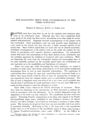
be practical clinically. Referring to I.‘&. 1. the long axis of the mandibular
incisor was set at 90 degrees to the mandibular plane in those cases having a
25 degree Il’rwnkfort-rrlillldiI)ulal. 1)Iane angle (FMPA). As the l<‘MPA in-
*Presented before the Charles H. l’weed Foundation for Orttmlontk Kesearctl, Drake
Hotel, Chicago. Illinois, Oct. Xl, 1953.
710
2. creased by 1 degree, the incisor was set 1 degree to t,he lingual, or 89 degrees
to the mandibular plane. This ratio was maintained until the angle reached
about 33 degrees, at which point the incisor would be placed at -8 degrees, or
82 degrees to the mandibular plane. As the FMPA exceeded 33 degrees; the
-8 degrees was maintained, because it was our convict,ion that -8 degrees was
the maximum lingual position possible for an incisor. Similar limitations were
observed in the labial positioning, using 6 as the maximum labial position,
regardless of how favorable the F’MPA might be.
FMPA 20” = +s 1x1
FMPA 21” = 4 IMA
FMPA 282” = 3 IMA
FMPA 23” z 2 TMA
FMPA 24” = 1 IMA
FMPA 25” = 0 IM4
FMPA 26” = -1 IM:k
FMPA 27” = -2 IMA
FMPA 28” = -3 IMA
FMPA 29” = -4 IMA
FMPA 30” = -5 IMA
FMPA 31” z -6 IMA
FiWPA 3”” = -7 IMA
FMPA 3:” = -8 IMA
Fig. l.-Formula for positioning lower anterior teeth.
When Tweed2 demonstrated the use of the lateral head x-ray to determine
the angulation of teeth, the diagnostic setup became much more accurate. A
tracing made from a lateral head x-ray of any orthodontic case would show
definitely the relationship of the mandibular incisor to the mandibular plane.
Thus, we can eliminate the guesswork from the positioning of this tooth. Since
we begin the diagnost,ic setup in all cases with the positioning of the lower
incisor, it is very important to know the angulation of this tooth in the mal-
occlusion. Using the formula developed in the past, the desired position can
also be drawn on the tracing (Fig. 4). By a comparison of these two lines on
the tracing, it is possible to determine the exact measurement, in millimeters.
that the incisal edge must be changed. In altering the angulation of the incisor,
care must be taken to maintain the apical root end in the apical base. As treat-
ment progresses, similar x-ray films can show the new angulations of the in-
cisors. Cases have been reported where these teeth hare been moved as much
as 25 degrees. For t,his reason, our formula was expanded to allow for eonsid-
crably more latitude in lingual positioning.
For the benefit of those readers who may be unfamiliar with the technique
of constructing a setup, let us consider those things which are necessary for its
preparation. Plaster casts of the malocclusion (Fig. 2), instruments (Fig. 3))
intraoral x-ray films, a photograph ot’ the patient, and a tracing of a lateral
head x-ray (Fig. 4) are included. On the t,racing of the lateral head x-ray
shown, the Frankfort plane is indicated by lint II-R, the mandibular plane by
il-C, the long axis of the mandibular incisor by C-K, and the apex by D. The
desired position of the long axis of the incisor is D-E. In this particular case,
the FMPA is 27 degrees, the incisor-mandibular plane angle (IMPA) is 102 de-
4. grees, and tbc ~rallkfort-marldibular incisor angle (E’MIA) is 57 degrees. With
a 27 degrw P’MI’A, our formula indicates that this tooth should lw positiowd
at -2 dcglws, or 8X &g1w. This is 14 degrees differcnt, from the 102 degrrcs
shown on the tracing. Therefore, the dotted line, D-E, is drawn from the apes
of the mandibular incisor to the Frankfort plane, 14 degrees lingual t,o C-R,
the original position of the tooth. With calipers, or a millimeter gauge, the
distance from the tip of the incisor to the dotted line can be measmwl. This is
thc distance that the tooth mnst bc tipped to the lingual on the sctnp.
Now wc arc ready to begin the actual construction. First, we propose to
dissect and remove the teeth on the left side of the mandibular model, leaving
only t,hc most distal tooth. With a spiral plast,er saw blade, a horizontal cut is
made deep into the base of the model. ITsing a ribbon saw blade, vertical ruts
are made between the incisors down t,o the original horizontal cut, allowing t,wo
incisors to bc removed (Fig. 5). It is very important that, a sufficient amount
of the root portion be rcmovcd to resemble the normal length of the root. The
incisors on the opposite side arc retained on the model, for the time being, to
swvc as a guide for repositioning the teeth previously removed. A second hori-
zontal cut is made with the spiral saw blade about 3 mm. rootwisc from their
gingiva under the remaining teeth to 1~ remorcd on the left side. The models
should be trimmed as shown in Fig. 6. The teeth should be carved as shown in
Fig. 7. Note that the teeth arc not trimmed on the buccal or lingual surfaces.
5. 744
Jn preparation for positioning the teeth, wc flow beeswax into the groove
wrvcd on the apical base. Then a small amount of beeswax is attached to the
apical end of the wntral and latrral irwisors, and th(y art’ positioned on the
Vig. f;.--Mandibular n~wlel, trimmed, after removal of the teeth on left side.
Fig. 7.-Labial. buccal, and mesial views of teeth tknmed for diagnostic setup.
cast. In carrying out this step of the procedure, it is essential that the apices
of the teeth should not be shifted to the labial or lingual, while the incisal
edges must hc moved exactly the distance determined on t,he tracing, in this
6. $;yr4,; DIAQNOSTIC BETTJP WITH CONHlDERhTlON Ok’ TIIIRD DlMENSION 745
I
case 6.8 mm. This goal can best be accomplished by keeping the labial art por-
tion of these teeth in the same plane as that of the remaining art portion of the
model and, with the calipers, measuring from the labial side of the right central
incisor to the labial side of the left central incisor and making this space 6.8
mm. When the central and lateral incisors are repositioned, and are in proper
axial inclination, we seal them onto the cast with red setup wax. Then we posi-
tion the canine in proper relationship with the lateral incisor and the apical
base, securing it with a small amount of beeswax. Similarly, we position the
remaining dissected teeth. In studying the x-ray pictures and models of the
case at hand, if it is evident that the distal molar is tipped forward because of
Fig. S.-Views of mandibula,r model with teeth on left side repositioned.
lack of mesial support, it is possible to gain space by tipping the tooth into
normal axial inclination. If space is st,ill lacking after taking advantage of this
possibilit,y, it will be necessary to remove dental units. In such a case, ordi-
narily the first premolars are eliminated, after which the second premolar is
moved up into contact with the canine. Under no circumstances should arch
length be gained by increasing the third dimension, or arch width, greater than
the apical base can accommodate. The amount of unused space after the teeth
are positioned, if any, is a very important guide in t,reatment planning. The
anchorage problem increases as this space decreases. (Fig. 8)
The teeth on t,hc opposite side arr now dissected 3 mm. below the gingival
margin, including the incisors, and the root portions are trimmed as before.
7. As the?’ art‘ positioucvl, thcay sl10uld ))(I art iculatctl to tlrv mandibIllal* ttvth. At
t’his time, the orthodontist leas an or)l,ortllrlitv to position the teeth in tllv yeI’>
hWt, occlusion, including inclined plane relationship. Tooth discrepancies ma!-
be discovered and given marls- consideration in trcatmcnt planning.
In cases where the scc~ondmolars ar(’ fnllj- erupted, they should be rcmovt~d
from the! casts and placed in contact I-ith the first molars and in good occlu-
sion. If thc.v are not fully c~rllptcd, imprcssilons of thrse teeth can be made in
the mouth at the end of basic trcatmc>nt a11d plastrr models of thcssctteeth made
vhich can bc added IO the, sotlIp at that time. Tlaving t,lic second molars in
place is essential, particnlarly ii’ the setup is to 1~’ used as il. pattern over which
a positioner is to he fabricated for the final drtailcvl tooth positioning.
The final waxing of thck scatup is eomplvttvl, using pink st+up wax for this
part of the t,echniqnc. With a hot spatula, w flow pink was bctwcen the root,
portions of the tzeth, slight1.v overfilling all thv voids on lhr huccal, labial, and
lingual areas of the model. Aft?~ tllc was has liardcrid, it should bc carved
to reproduce exactly the gingival arias around thust&h (Fig. 13 ). Jf this is
successfully accomplished, tliclrc u-ill hv no irritation from wearing a positioner.
8. A cwcfully executed setup, following the abo~c tcchniquc, will aid an)
operator tremendously in making decisions with regard t,o the advisability 01
eliminating dental units. As t,ho plaster teeth arc plawd on the plaster apical
base, we have noncrctc evidence as to whcthcr or not there is sufficient basal boric
to accommodate> all the teeth in proper’ position. There is no s,vstcm of measurc-
merit. of teeth that will reveal so trac and complete a picture. Unusual benefit
Fig. Il.-Front and lateral vimm of completed setup.
Fig. iZ.-Tooth positioner.
is to be derived from the fact, that in this way all three dimensions of the denture
may be studied. The setup will disclosc tooth discrepancies, as well as give
advance notice of anchorage problems and it provides a pattern over which to
fabricate ideal arch mires during treatment. With such a complete setup, a
positioner can be prepared in advance so that it can be placed on the day con-
ventional appliances are removed (Fig. 12). (ireat advantage is gained b>
placing a positioner immediately. Finally, the diagnostic setup is particularly
valuable in teaching ‘ ’ponngst~ers ’ ’ who are unfamiliar with the Tweed philoso-
phy of treatment and, if intclligentl~- esecut,ed, some of the “oldsters” might be
amazed by the bcnctits to be derived.
9. 748 Am. J. Orthodontics
October. 1956
REFERESCEY
1. Tweed, C. H.: Frankfort-~~andibular Plane ;2ngle in Ortllodontic Diagnosis, Classification,
Treatment Planning and Prognosis, AM. .T. OKTHOTKXTICS ANT) ORAL RUFG. 32: 175
230, 194%
2. Tweed, C. H.: Evolutionary trends in Ortl~odontics, Past, Present and F’nturc, AM. 1.
ORTH~~OXWX 39: 81, 19.53.