SlideShare a Scribd company logo
1 of 38
Description of bridge
• Location of the bridge:
Chemin Côte-des-Neiges(North)/Chemin Remembrance(West)
Description of bridge
• Ownership of infrastructure:
It is under municipal ownership and jurisdiction of the City of
Montreal.
• Function:
It is used as a link between the downtown area and residential
areas such as Cote des Neiges and Mont-Royal while also
providing access for a return road under the bridge.
Description of bridge
• Bridge composed of:
oMajor Structural Components:
 Concrete: Beams, columns, foundations, bridge deck
 Steel: Reinforcing bars, stirrups, ties
oMinor Structural Components:
Steel railings, concrete barriers, asphalt on the bridge
deck
DESCRIPTION OF PERFORMANCE
AND LOADING CRITERIA
• Usage of the
Structure:
oThe bridge contains 3
lanes of one-way traffic
with no apparent
congestion.
oOverloaded trucks are
prohibited.
oNo sidewalk for
pedestrians.
DESCRIPTION OF PERFORMANCE
AND LOADING CRITERIA
• The structure is exposed to the following
conditions:
o De-icing salts
o Car exhaust, although it might not be severe, as there were
no apparent traffic congestion on or below the bridge.
o Retaining walls, column bases and supports all are in contact
with soil & groundwater. No obvious drainage system is
present.
DISCUSSION OF PRELIMINARY
FINDINGS
• The main cause of deterioration in the bridge appears to be
corrosion. It is evident all along the bridge deck and most of
the columns due to spalling of the concrete cover and rust
staining.
DISCUSSION OF PRELIMINARY
FINDINGS
• Some of the concrete columns are suffering from scaling
and cracks visible at the base of the column.
DISCUSSION OF PRELIMINARY
FINDINGS
• Rust and efflorescence of salt are apparent on the side and
under the bridge deck as reddish/orange and white stains
respectively.
DISCUSSION OF PRELIMINARY
FINDINGS
• Core samples appear to have been taken from the columns
and beams as cylindrical holes are evident.
RECOMMENDATIONS CONCERNING
FUTURE ACTIONS
• According to the records of la Ville de
Montreal, the deterioration rating is 68, hence
it is in a “Deficient” state.
• A plan to eliminate the overpass is in place.
However, if this does not happen before 2015,
repairs will be done to the overpass.
RECOMMENDATIONS CONCERNING
FUTURE ACTIONS
• Since the bridge is in deficient state and not a
critical one, no immediate action is required
even though the overpass is severely
damaged.
• If however repairs are done today, they would
cost less than as planned in 2015 since
deterioration due to corrosion and sulfate
attacks would increase exponentially with
time.
Bridge Deck
Durability Risks:
1. Corrosion
• Exposure Conditions
• Visual Signs of Deterioration
2. Freeze-Thaw Cycles
• Expose Conditions
• Visual Signs of Deterioration
3. Efflorescence
• Exposure Conditions
• Visual Signs of Deterioration
Corrosion
Durability Risks:
1. Bridge Deck
• Exposure Conditions
• Visual Signs of Deterioration
2. Columns, Beams & Rail End
• Exposure Conditions
• Visual Signs of Deterioration
Freeze-Thaw Cycles
Durability Risks:
1. Bridge Deck
• Exposure Conditions
• Visual Signs of Deterioration
2. Columns, Beams & Rail End
• Exposure Conditions
• Visual Signs of Deterioration
Alkali-Silicate Reaction (ASR)
3. Columns, Beams & Rail End
• Expose Conditions
• Visual Signs of Deterioration
Efflorescence
3. Bridge Deck
• Exposure Conditions
• Visual Signs of Deterioration
Bridge Deck
1
2
3
Columns, Beams & Rail End
1
2
1
1
2
Structural/loading factors which may
increase/diminish the risk
• Dynamic loading
• Fatigue loads
• High permanent snow load
• Heavy dynamic natural loads
Testing for Corrosion
Short-Pulse Radar:
 Will be used to detect the reinforcing steel locations
 Will also detect delamination in the bridge deck.
 One of the only available methods that works through asphalt overlays.
Rolling Pachometer:
 Will be used to find the location of the reinforcing steel and compared
with the results of the short-pulse radar to achieve higher accuracy.
 The rate of deterioration of the bars can be found in terms of a reduction
of its relative size.
 A damage map can then be created and analyzed.
Testing for Efflorescence & ASR
Lab Test of Effloresced Solid:
 A sample of the effloresced solid will be tested in the lab to
determine its composition.
UV Fluorescence technique for ASR:
 This is a destructive test.
 A solution of uranyl acetate solution is sprayed
on a fresh fracture surface.
 A viewing box that emits UV light is used to
detect the affected regions.
 This technique is fast, easy and accurate.
 Will be used on bridge deck and rail end.
Testing for Carbonation
Phenolphthalein Test:
 Will be used to determine the rate of
Carbonation.
 A fractured surface will be sprayed with
phenolphthalein turning the concrete
pink, and carbonated areas will remain
unchanged.
 If carbonation is found to be extensive, a core can be taken
along with chemical profiling to find the “depth of
carbonation”.
 It is fast, cheap and reliable.
 Will be tested mainly on the columns
Test for Transport Properties
The ISAT will be used to analyze transport properties as
it is not affected by carbonation and chloride content.
Initial Surface Absorbtion Test (ISAT):
 It’s a semi-destructive technique
 Field concrete must have been exposed to at least 48
hours of ambient temperature and humidity.
 The rate of water absorbed into an unsaturated
concrete surface is measured.
 Results will be used to determine the concrete’s
surface transport properties.
 It will be applied on the bridge deck.
Test for Compressive Strength
Use core data if available
Pullout test:
 Will be used to estimate the compressive strength of concrete in-situ.
 Shear strength can be also be found as the test measures a combination of tensile and shear
strength.
 Should be performed on a few different locations along the beam and columns to achieve a more
global estimation of compressive strength.
Testing for Sulphate Attack
Schmidt Rebound Hammer:
 Hammer should be regularly calibrated.
 Will be used predominantly along column length at regular intervals to
determine whether there is a relative loss in compressive strength at the
column base that can be possibly attributed to sulphate attack, calling for
more in-depth investigations.
Corrosion Repair
Members to be repaired: bridge deck and the columns
Chloride Removal:
• Electrochemical Chloride Extraction (ECE) – ONLY if justified
by chloride concentrations as it will disrupt traffic and cause
additional costs to this already expensive method.
Concrete Removal (used for concrete above the bridge deck):
• By impacting – using a pneumatic chipping hammer.
• By hydro removal – whenever the use of the pneumatic
hammer is not applicable.
Undercutting and Exposing Rebar:
• Should be done around and under all corroded rebar, so
that the rebar’s full circumference could be cleaned.
• Replace steel if 25% of cross-sectional area is lost (or 20% if
the 2 bars are in close proximity).
*NOTE: Structural review required before removal of significant
amounts of concrete to determine if support (e.g. shoring) is
required*
Corrosion Repair
Preventative Measure (before placing new concrete):
• Installing a discrete sacrificial anode – Zinc “puck”.
• Should be connected at joints of rebars for maximum efficiency.
• Care should be taken in placing the “pucks” to ensure that all the
steel rebar is protected.
Concrete Placement (used for concrete below the bridge deck):
• The surface should be cleaned from bond inhibiting materials by
hydroblasting.
• Form and pump placement will be implemented as it is works well
for overhead and vertical applications where congested
reinforcement is present (columns, beams, deck, and rail ends).
Consolidation and bonding is provided by the formwork pressure.
Preventative Measure (after placing new concrete):
• Applying a thin epoxy or mortar overlay all over surface to prevent
further ingress of chlorides and moisture. The epoxy would be
placed on the structural members
*NOTE: The membrane should suffice after applying ECE, but the zinc
pucks will be added for additional protection*
ASR Repair
Members to be repaired: bridge deck
Chemical injection with lithium salts and CO2:
• Should be done in conjunction with the
electrochemical chloride removal where the
lithium ions will replace the chlorides in the
concrete.
• Its use along with ECE may justify both their
costs
Preventative measure:
• Applying a thick overlay of ASR resistant
concrete to encapsulate the affected region and
prevent ingress of moisture.
• ASR ceases at RH < 85%
Crack Repair
When extensive cracking is present, it could lead
to deleterious effects and durability issues, thus
an action should be taken.
For passive cracks:
• The overlay provided for corrosion and ASR
repairs should be sufficient to provide a
moisture barrier
For active cracks:
• There were big cracks at the bottom and at the
side of the bridge deck which made us suspect
that these cracks would be active.
• Stitching of the cracks to provide a tensile force
to prevent further propagation and also acts to
close them.
• Done in conjunction with the overlays provided
before as it does not seal moisture on its own.
Crack Repair
The repair technique also depends on the
type of member and the location of the
crack.
For non-structural members (rail ends):
• Rout and Seal technique will be used to fill
significant cracks with flexible sealant to
minimize chemical and physical ingress.
• This method is used for its simplicity.
• It requires minimum 6mm opened space
to take sealant. In some cases, flexible
sealants and specialized coatings are used
for flexurally active cracks.
Crack Repair
For structural members (columns, beams and deck):
• Drilling and Plugging technique is used to core
deep and straight cracks. Then a rigid
impermeable plug of bitumen or mortar material
is inserted to replace the crack and the
deteriorated concrete around it.
• Good for walls or beams with deep vertical cracks
Preventative Measure:
• During the repairs of active cracks, NDT monitoring
such as Acoustic emission, crack width
measurement, crack inventory should be
implemented for preventative maintenance to
detect any potential crack formation. The acoustic
emission will be placed to monitor the active
cracks in the structural members, and the return
period for the crack width measurement and the
inventory will be 5 years as the bridge is in critical
condition.
Preventative Measures
Discrete sacrificial anode – Zinc “puck”
• Placed strategically on rebar exposed
during undercutting
• To prevent incipient anode forming
adjacent to new patch
Thin bonded overlay
• Epoxy/Mortar
• Compatibility
• Applied to columns, deck, beams and
rail ends
• Prevent further ingress of moisture and
deleterious agents
Preventative Measures
Thick unbonded overlay
• Concrete with its own reinforcement
• Bridge resurfacing (deck only)
• Limit permeability of underlying
concrete
• Compatibility not an issue
Long-term Maintenance & Monitoring
Acoustic Emission
• Set-up along deck, columns and the ends of the beams.
• Set a threshold value
• Record counts above threshold value
• Determine crack location
• Evaluate whether new crack or old one propagating
Long-term Maintenance & Monitoring
ILRIS-3D – Intelligent Laser Ranging and
Imaging System
o Condition status model
• Reverse engineering and load
modeling of structure
• Data is complete
• No traffic interruption
• Can be combined with monitoring
under a load test
o Micro-damage analysis
• High density scans to reveal
hairline cracks
• Apparent in both bare and coated
surfaces
Long-term Maintenance & Monitoring
Routine Inspection
• Should be scheduled every 2 years at the least.
• Mostly visual to determine any deterioration that is initiating
• Evaluate effectiveness of repairs done
• Crack width measurement
• Crack inventory
References
• http://wins-
ndt.com/DEV/admin/data/upimages/bridge-
acousticemission-3.jpg
• http://www.mastrad.com/avgcwg.jpg
• http://www.annarbor.com/assets_c/2010/05/
Stadium_bridges_inspection-thumb-350x232-
40166.jpg
• 527 notes

More Related Content

What's hot

Inspection and maintenance of bridges In India
Inspection and maintenance of bridges In IndiaInspection and maintenance of bridges In India
Inspection and maintenance of bridges In IndiaKhyati Saggu
 
02725 sewer manholes
02725 sewer manholes02725 sewer manholes
02725 sewer manholesAni Alikaj
 
Special Concreting Techniques
Special Concreting Techniques Special Concreting Techniques
Special Concreting Techniques GAURAV. H .TANDON
 
10 Well Abandonment Presentation Jan 29
10 Well Abandonment Presentation Jan 2910 Well Abandonment Presentation Jan 29
10 Well Abandonment Presentation Jan 29Will Butler, P.Eng
 
rock anchor methodology
rock anchor methodologyrock anchor methodology
rock anchor methodologyGautam Sharma
 
tunnelling scope, construction techniques and necessity
tunnelling scope, construction techniques and necessitytunnelling scope, construction techniques and necessity
tunnelling scope, construction techniques and necessityShashank Gaurav
 
Repair Options for Concrete Roadways
Repair Options for Concrete RoadwaysRepair Options for Concrete Roadways
Repair Options for Concrete RoadwaysJill Reeves
 
Rock bolt and anchoring
Rock bolt and anchoringRock bolt and anchoring
Rock bolt and anchoringAmit Jagtap
 
Soil Nails Reinforcement - Design nails soil stabilization --مسامير قضبان تسل...
Soil Nails Reinforcement - Design nails soil stabilization --مسامير قضبان تسل...Soil Nails Reinforcement - Design nails soil stabilization --مسامير قضبان تسل...
Soil Nails Reinforcement - Design nails soil stabilization --مسامير قضبان تسل...Dr.Youssef Hammida
 
NATM (New Austrian Tunneling Method ) in Tunneling
NATM (New Austrian Tunneling Method ) in TunnelingNATM (New Austrian Tunneling Method ) in Tunneling
NATM (New Austrian Tunneling Method ) in TunnelingHamed Zarei
 
Calculation note 29 11-2014
Calculation note 29 11-2014Calculation note 29 11-2014
Calculation note 29 11-2014Khaled Eid
 
Rock bolts simon madiro
Rock bolts   simon madiroRock bolts   simon madiro
Rock bolts simon madiroSimon Madiro
 
UNDERWATER CONCRETING TECHNIQUES
UNDERWATER CONCRETING TECHNIQUESUNDERWATER CONCRETING TECHNIQUES
UNDERWATER CONCRETING TECHNIQUESShivananda Roy
 

What's hot (20)

Inspection and maintenance of bridges In India
Inspection and maintenance of bridges In IndiaInspection and maintenance of bridges In India
Inspection and maintenance of bridges In India
 
02725 sewer manholes
02725 sewer manholes02725 sewer manholes
02725 sewer manholes
 
Special Concreting Techniques
Special Concreting Techniques Special Concreting Techniques
Special Concreting Techniques
 
Tremie
TremieTremie
Tremie
 
10 Well Abandonment Presentation Jan 29
10 Well Abandonment Presentation Jan 2910 Well Abandonment Presentation Jan 29
10 Well Abandonment Presentation Jan 29
 
rock anchor methodology
rock anchor methodologyrock anchor methodology
rock anchor methodology
 
Guidelines
GuidelinesGuidelines
Guidelines
 
tunnelling scope, construction techniques and necessity
tunnelling scope, construction techniques and necessitytunnelling scope, construction techniques and necessity
tunnelling scope, construction techniques and necessity
 
Repair Options for Concrete Roadways
Repair Options for Concrete RoadwaysRepair Options for Concrete Roadways
Repair Options for Concrete Roadways
 
Bridge rehabilitation
Bridge rehabilitationBridge rehabilitation
Bridge rehabilitation
 
Rock bolt and anchoring
Rock bolt and anchoringRock bolt and anchoring
Rock bolt and anchoring
 
Site visit presentation: Kwun Tong line extension
Site visit presentation: Kwun Tong line extensionSite visit presentation: Kwun Tong line extension
Site visit presentation: Kwun Tong line extension
 
Lining in tunnels
Lining in tunnelsLining in tunnels
Lining in tunnels
 
Soil Nails Reinforcement - Design nails soil stabilization --مسامير قضبان تسل...
Soil Nails Reinforcement - Design nails soil stabilization --مسامير قضبان تسل...Soil Nails Reinforcement - Design nails soil stabilization --مسامير قضبان تسل...
Soil Nails Reinforcement - Design nails soil stabilization --مسامير قضبان تسل...
 
NATM (New Austrian Tunneling Method ) in Tunneling
NATM (New Austrian Tunneling Method ) in TunnelingNATM (New Austrian Tunneling Method ) in Tunneling
NATM (New Austrian Tunneling Method ) in Tunneling
 
Alan sutton
Alan suttonAlan sutton
Alan sutton
 
Calculation note 29 11-2014
Calculation note 29 11-2014Calculation note 29 11-2014
Calculation note 29 11-2014
 
Rock bolts simon madiro
Rock bolts   simon madiroRock bolts   simon madiro
Rock bolts simon madiro
 
Load dev-silo-design
Load dev-silo-designLoad dev-silo-design
Load dev-silo-design
 
UNDERWATER CONCRETING TECHNIQUES
UNDERWATER CONCRETING TECHNIQUESUNDERWATER CONCRETING TECHNIQUES
UNDERWATER CONCRETING TECHNIQUES
 

Viewers also liked

Actividad didactica para preescolar
Actividad  didactica para preescolarActividad  didactica para preescolar
Actividad didactica para preescolaremerita761711
 
A caixa e_a_habitação_rural_caderno_1
A caixa e_a_habitação_rural_caderno_1A caixa e_a_habitação_rural_caderno_1
A caixa e_a_habitação_rural_caderno_1Ely Barros
 
Concept du Cercle de Abondance
Concept du Cercle de AbondanceConcept du Cercle de Abondance
Concept du Cercle de AbondanceH-CASH CONCEPT
 
Herminda navarro cárdenas mapa conceptual 1
Herminda navarro cárdenas mapa conceptual 1Herminda navarro cárdenas mapa conceptual 1
Herminda navarro cárdenas mapa conceptual 1Herminda Navarro
 
Liliana hernandez actividad1_mapa_c
Liliana hernandez actividad1_mapa_cLiliana hernandez actividad1_mapa_c
Liliana hernandez actividad1_mapa_cUDES
 
Mapa conceptual lizday lara c.
Mapa conceptual lizday lara c.Mapa conceptual lizday lara c.
Mapa conceptual lizday lara c.LIZDAY1974
 
Presentacion Tecnologia
Presentacion TecnologiaPresentacion Tecnologia
Presentacion Tecnologiafredher
 
D&B Valued Service Method - 20130509
D&B Valued Service Method - 20130509D&B Valued Service Method - 20130509
D&B Valued Service Method - 20130509David Chung
 
Gerencia de proyectos de tecnología educativa
Gerencia de proyectos de tecnología educativaGerencia de proyectos de tecnología educativa
Gerencia de proyectos de tecnología educativaanny muñoz
 

Viewers also liked (20)

Actividad didactica para preescolar
Actividad  didactica para preescolarActividad  didactica para preescolar
Actividad didactica para preescolar
 
Aniversario Tierra Amarilla
Aniversario Tierra AmarillaAniversario Tierra Amarilla
Aniversario Tierra Amarilla
 
Rol del docente y rol del alumno
Rol del docente y rol del alumnoRol del docente y rol del alumno
Rol del docente y rol del alumno
 
A caixa e_a_habitação_rural_caderno_1
A caixa e_a_habitação_rural_caderno_1A caixa e_a_habitação_rural_caderno_1
A caixa e_a_habitação_rural_caderno_1
 
Concept du Cercle de Abondance
Concept du Cercle de AbondanceConcept du Cercle de Abondance
Concept du Cercle de Abondance
 
Empresa
EmpresaEmpresa
Empresa
 
Slideshare alejandra valderrama
Slideshare alejandra valderramaSlideshare alejandra valderrama
Slideshare alejandra valderrama
 
Perfíl janneth patricia romo g.
Perfíl janneth patricia romo g.Perfíl janneth patricia romo g.
Perfíl janneth patricia romo g.
 
Herminda navarro cárdenas mapa conceptual 1
Herminda navarro cárdenas mapa conceptual 1Herminda navarro cárdenas mapa conceptual 1
Herminda navarro cárdenas mapa conceptual 1
 
Liliana hernandez actividad1_mapa_c
Liliana hernandez actividad1_mapa_cLiliana hernandez actividad1_mapa_c
Liliana hernandez actividad1_mapa_c
 
Slogan
SloganSlogan
Slogan
 
Tiempolibre
TiempolibreTiempolibre
Tiempolibre
 
Orla
OrlaOrla
Orla
 
Mapa conceptual lizday lara c.
Mapa conceptual lizday lara c.Mapa conceptual lizday lara c.
Mapa conceptual lizday lara c.
 
Next 05 ppt
Next 05 pptNext 05 ppt
Next 05 ppt
 
6 pasos
6 pasos6 pasos
6 pasos
 
Presentacion Tecnologia
Presentacion TecnologiaPresentacion Tecnologia
Presentacion Tecnologia
 
D&B Valued Service Method - 20130509
D&B Valued Service Method - 20130509D&B Valued Service Method - 20130509
D&B Valued Service Method - 20130509
 
Fisica oriol
Fisica oriolFisica oriol
Fisica oriol
 
Gerencia de proyectos de tecnología educativa
Gerencia de proyectos de tecnología educativaGerencia de proyectos de tecnología educativa
Gerencia de proyectos de tecnología educativa
 

Similar to Final Presentation

Inspection,Repair and Strengthening of PSC Bridge.
Inspection,Repair and Strengthening of PSC  Bridge.Inspection,Repair and Strengthening of PSC  Bridge.
Inspection,Repair and Strengthening of PSC Bridge.Mohammad Furqan
 
Assessment of Underpass on Clark Street and Van Horne
Assessment of Underpass on Clark Street and Van HorneAssessment of Underpass on Clark Street and Van Horne
Assessment of Underpass on Clark Street and Van HorneMichael Masi, Jr. Eng.
 
IRJET- The Rehabilitation Techniques for Irwin Bridge
IRJET-  	  The Rehabilitation Techniques for Irwin BridgeIRJET-  	  The Rehabilitation Techniques for Irwin Bridge
IRJET- The Rehabilitation Techniques for Irwin BridgeIRJET Journal
 
Uses of special kind of technologies for implementation of special kind of st...
Uses of special kind of technologies for implementation of special kind of st...Uses of special kind of technologies for implementation of special kind of st...
Uses of special kind of technologies for implementation of special kind of st...Rajesh Prasad
 
Your Score 1420Not bad. Your score means youre slightly bette.docx
Your Score 1420Not bad. Your score means youre slightly bette.docxYour Score 1420Not bad. Your score means youre slightly bette.docx
Your Score 1420Not bad. Your score means youre slightly bette.docxodiliagilby
 
Pt slab design philosophy with slides and pictures showing benefit
Pt slab design philosophy  with slides and pictures showing benefitPt slab design philosophy  with slides and pictures showing benefit
Pt slab design philosophy with slides and pictures showing benefitPerwez Ahmad
 
self-compacting concrete
self-compacting concrete self-compacting concrete
self-compacting concrete Sreekutty S
 
Structural and stability assessment for ex-pit dump toe (final)
Structural and stability assessment for ex-pit dump toe (final)Structural and stability assessment for ex-pit dump toe (final)
Structural and stability assessment for ex-pit dump toe (final)John Latilla
 
PDL’s Construction Development (Technical) Training Session-I_Structural.pptx
PDL’s Construction Development (Technical) Training Session-I_Structural.pptxPDL’s Construction Development (Technical) Training Session-I_Structural.pptx
PDL’s Construction Development (Technical) Training Session-I_Structural.pptxChristopherThomas578171
 
Protecting Occupied Buildings from Process Tank Rupture Spillage
Protecting Occupied Buildings from Process Tank Rupture SpillageProtecting Occupied Buildings from Process Tank Rupture Spillage
Protecting Occupied Buildings from Process Tank Rupture SpillageAdvisian
 
Maintenance &amp; repair of steel bridges
Maintenance &amp; repair of steel bridgesMaintenance &amp; repair of steel bridges
Maintenance &amp; repair of steel bridgesnaveen kumar
 
Asif2 CONSTRUCTION_OF_RIGID_PAVEMENT.pptx
Asif2 CONSTRUCTION_OF_RIGID_PAVEMENT.pptxAsif2 CONSTRUCTION_OF_RIGID_PAVEMENT.pptx
Asif2 CONSTRUCTION_OF_RIGID_PAVEMENT.pptxsfQyoom
 
Bridge inspection,maintenance and repair
Bridge inspection,maintenance and repairBridge inspection,maintenance and repair
Bridge inspection,maintenance and repairKartikSuryawanshi2
 
repairandrehabilitation-150105022737-conversion-gate02.pdf
repairandrehabilitation-150105022737-conversion-gate02.pdfrepairandrehabilitation-150105022737-conversion-gate02.pdf
repairandrehabilitation-150105022737-conversion-gate02.pdf027NaveenKumarV
 
MODULE 4 Special Concrete (1).ppt
MODULE 4 Special Concrete (1).pptMODULE 4 Special Concrete (1).ppt
MODULE 4 Special Concrete (1).pptVaibhavSoni742163
 

Similar to Final Presentation (20)

Inspection,Repair and Strengthening of PSC Bridge.
Inspection,Repair and Strengthening of PSC  Bridge.Inspection,Repair and Strengthening of PSC  Bridge.
Inspection,Repair and Strengthening of PSC Bridge.
 
Assessment of Underpass on Clark Street and Van Horne
Assessment of Underpass on Clark Street and Van HorneAssessment of Underpass on Clark Street and Van Horne
Assessment of Underpass on Clark Street and Van Horne
 
IRJET- The Rehabilitation Techniques for Irwin Bridge
IRJET-  	  The Rehabilitation Techniques for Irwin BridgeIRJET-  	  The Rehabilitation Techniques for Irwin Bridge
IRJET- The Rehabilitation Techniques for Irwin Bridge
 
Uses of special kind of technologies for implementation of special kind of st...
Uses of special kind of technologies for implementation of special kind of st...Uses of special kind of technologies for implementation of special kind of st...
Uses of special kind of technologies for implementation of special kind of st...
 
Your Score 1420Not bad. Your score means youre slightly bette.docx
Your Score 1420Not bad. Your score means youre slightly bette.docxYour Score 1420Not bad. Your score means youre slightly bette.docx
Your Score 1420Not bad. Your score means youre slightly bette.docx
 
Pt slab design philosophy with slides and pictures showing benefit
Pt slab design philosophy  with slides and pictures showing benefitPt slab design philosophy  with slides and pictures showing benefit
Pt slab design philosophy with slides and pictures showing benefit
 
Concrete
ConcreteConcrete
Concrete
 
self-compacting concrete
self-compacting concrete self-compacting concrete
self-compacting concrete
 
Structural and stability assessment for ex-pit dump toe (final)
Structural and stability assessment for ex-pit dump toe (final)Structural and stability assessment for ex-pit dump toe (final)
Structural and stability assessment for ex-pit dump toe (final)
 
8.ppt
8.ppt8.ppt
8.ppt
 
PDL’s Construction Development (Technical) Training Session-I_Structural.pptx
PDL’s Construction Development (Technical) Training Session-I_Structural.pptxPDL’s Construction Development (Technical) Training Session-I_Structural.pptx
PDL’s Construction Development (Technical) Training Session-I_Structural.pptx
 
TANK 13042023.pptx
TANK 13042023.pptxTANK 13042023.pptx
TANK 13042023.pptx
 
Unit 5.pptx
Unit 5.pptxUnit 5.pptx
Unit 5.pptx
 
Protecting Occupied Buildings from Process Tank Rupture Spillage
Protecting Occupied Buildings from Process Tank Rupture SpillageProtecting Occupied Buildings from Process Tank Rupture Spillage
Protecting Occupied Buildings from Process Tank Rupture Spillage
 
Maintenance &amp; repair of steel bridges
Maintenance &amp; repair of steel bridgesMaintenance &amp; repair of steel bridges
Maintenance &amp; repair of steel bridges
 
Asif2 CONSTRUCTION_OF_RIGID_PAVEMENT.pptx
Asif2 CONSTRUCTION_OF_RIGID_PAVEMENT.pptxAsif2 CONSTRUCTION_OF_RIGID_PAVEMENT.pptx
Asif2 CONSTRUCTION_OF_RIGID_PAVEMENT.pptx
 
Bridge inspection,maintenance and repair
Bridge inspection,maintenance and repairBridge inspection,maintenance and repair
Bridge inspection,maintenance and repair
 
Repair and Rehabilitation
Repair and RehabilitationRepair and Rehabilitation
Repair and Rehabilitation
 
repairandrehabilitation-150105022737-conversion-gate02.pdf
repairandrehabilitation-150105022737-conversion-gate02.pdfrepairandrehabilitation-150105022737-conversion-gate02.pdf
repairandrehabilitation-150105022737-conversion-gate02.pdf
 
MODULE 4 Special Concrete (1).ppt
MODULE 4 Special Concrete (1).pptMODULE 4 Special Concrete (1).ppt
MODULE 4 Special Concrete (1).ppt
 

Final Presentation

  • 1.
  • 2. Description of bridge • Location of the bridge: Chemin Côte-des-Neiges(North)/Chemin Remembrance(West)
  • 3. Description of bridge • Ownership of infrastructure: It is under municipal ownership and jurisdiction of the City of Montreal. • Function: It is used as a link between the downtown area and residential areas such as Cote des Neiges and Mont-Royal while also providing access for a return road under the bridge.
  • 4. Description of bridge • Bridge composed of: oMajor Structural Components:  Concrete: Beams, columns, foundations, bridge deck  Steel: Reinforcing bars, stirrups, ties oMinor Structural Components: Steel railings, concrete barriers, asphalt on the bridge deck
  • 5. DESCRIPTION OF PERFORMANCE AND LOADING CRITERIA • Usage of the Structure: oThe bridge contains 3 lanes of one-way traffic with no apparent congestion. oOverloaded trucks are prohibited. oNo sidewalk for pedestrians.
  • 6. DESCRIPTION OF PERFORMANCE AND LOADING CRITERIA • The structure is exposed to the following conditions: o De-icing salts o Car exhaust, although it might not be severe, as there were no apparent traffic congestion on or below the bridge. o Retaining walls, column bases and supports all are in contact with soil & groundwater. No obvious drainage system is present.
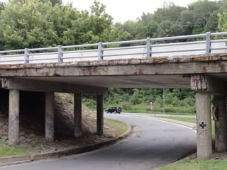
  • 7. DISCUSSION OF PRELIMINARY FINDINGS • The main cause of deterioration in the bridge appears to be corrosion. It is evident all along the bridge deck and most of the columns due to spalling of the concrete cover and rust staining.
  • 8. DISCUSSION OF PRELIMINARY FINDINGS • Some of the concrete columns are suffering from scaling and cracks visible at the base of the column.
  • 9. DISCUSSION OF PRELIMINARY FINDINGS • Rust and efflorescence of salt are apparent on the side and under the bridge deck as reddish/orange and white stains respectively.
  • 10. DISCUSSION OF PRELIMINARY FINDINGS • Core samples appear to have been taken from the columns and beams as cylindrical holes are evident.
  • 11. RECOMMENDATIONS CONCERNING FUTURE ACTIONS • According to the records of la Ville de Montreal, the deterioration rating is 68, hence it is in a “Deficient” state. • A plan to eliminate the overpass is in place. However, if this does not happen before 2015, repairs will be done to the overpass.
  • 12. RECOMMENDATIONS CONCERNING FUTURE ACTIONS • Since the bridge is in deficient state and not a critical one, no immediate action is required even though the overpass is severely damaged. • If however repairs are done today, they would cost less than as planned in 2015 since deterioration due to corrosion and sulfate attacks would increase exponentially with time.
  • 13. Bridge Deck Durability Risks: 1. Corrosion • Exposure Conditions • Visual Signs of Deterioration 2. Freeze-Thaw Cycles • Expose Conditions • Visual Signs of Deterioration 3. Efflorescence • Exposure Conditions • Visual Signs of Deterioration
  • 14. Corrosion Durability Risks: 1. Bridge Deck • Exposure Conditions • Visual Signs of Deterioration 2. Columns, Beams & Rail End • Exposure Conditions • Visual Signs of Deterioration
  • 15. Freeze-Thaw Cycles Durability Risks: 1. Bridge Deck • Exposure Conditions • Visual Signs of Deterioration 2. Columns, Beams & Rail End • Exposure Conditions • Visual Signs of Deterioration
  • 16. Alkali-Silicate Reaction (ASR) 3. Columns, Beams & Rail End • Expose Conditions • Visual Signs of Deterioration
  • 17. Efflorescence 3. Bridge Deck • Exposure Conditions • Visual Signs of Deterioration
  • 19. Columns, Beams & Rail End 1 2 1 1 2
  • 20. Structural/loading factors which may increase/diminish the risk • Dynamic loading • Fatigue loads • High permanent snow load • Heavy dynamic natural loads
  • 21. Testing for Corrosion Short-Pulse Radar:  Will be used to detect the reinforcing steel locations  Will also detect delamination in the bridge deck.  One of the only available methods that works through asphalt overlays. Rolling Pachometer:  Will be used to find the location of the reinforcing steel and compared with the results of the short-pulse radar to achieve higher accuracy.  The rate of deterioration of the bars can be found in terms of a reduction of its relative size.  A damage map can then be created and analyzed.
  • 22. Testing for Efflorescence & ASR Lab Test of Effloresced Solid:  A sample of the effloresced solid will be tested in the lab to determine its composition. UV Fluorescence technique for ASR:  This is a destructive test.  A solution of uranyl acetate solution is sprayed on a fresh fracture surface.  A viewing box that emits UV light is used to detect the affected regions.  This technique is fast, easy and accurate.  Will be used on bridge deck and rail end.
  • 23. Testing for Carbonation Phenolphthalein Test:  Will be used to determine the rate of Carbonation.  A fractured surface will be sprayed with phenolphthalein turning the concrete pink, and carbonated areas will remain unchanged.  If carbonation is found to be extensive, a core can be taken along with chemical profiling to find the “depth of carbonation”.  It is fast, cheap and reliable.  Will be tested mainly on the columns
  • 24. Test for Transport Properties The ISAT will be used to analyze transport properties as it is not affected by carbonation and chloride content. Initial Surface Absorbtion Test (ISAT):  It’s a semi-destructive technique  Field concrete must have been exposed to at least 48 hours of ambient temperature and humidity.  The rate of water absorbed into an unsaturated concrete surface is measured.  Results will be used to determine the concrete’s surface transport properties.  It will be applied on the bridge deck.
  • 25. Test for Compressive Strength Use core data if available Pullout test:  Will be used to estimate the compressive strength of concrete in-situ.  Shear strength can be also be found as the test measures a combination of tensile and shear strength.  Should be performed on a few different locations along the beam and columns to achieve a more global estimation of compressive strength.
  • 26. Testing for Sulphate Attack Schmidt Rebound Hammer:  Hammer should be regularly calibrated.  Will be used predominantly along column length at regular intervals to determine whether there is a relative loss in compressive strength at the column base that can be possibly attributed to sulphate attack, calling for more in-depth investigations.
  • 27. Corrosion Repair Members to be repaired: bridge deck and the columns Chloride Removal: • Electrochemical Chloride Extraction (ECE) – ONLY if justified by chloride concentrations as it will disrupt traffic and cause additional costs to this already expensive method. Concrete Removal (used for concrete above the bridge deck): • By impacting – using a pneumatic chipping hammer. • By hydro removal – whenever the use of the pneumatic hammer is not applicable. Undercutting and Exposing Rebar: • Should be done around and under all corroded rebar, so that the rebar’s full circumference could be cleaned. • Replace steel if 25% of cross-sectional area is lost (or 20% if the 2 bars are in close proximity). *NOTE: Structural review required before removal of significant amounts of concrete to determine if support (e.g. shoring) is required*
  • 28. Corrosion Repair Preventative Measure (before placing new concrete): • Installing a discrete sacrificial anode – Zinc “puck”. • Should be connected at joints of rebars for maximum efficiency. • Care should be taken in placing the “pucks” to ensure that all the steel rebar is protected. Concrete Placement (used for concrete below the bridge deck): • The surface should be cleaned from bond inhibiting materials by hydroblasting. • Form and pump placement will be implemented as it is works well for overhead and vertical applications where congested reinforcement is present (columns, beams, deck, and rail ends). Consolidation and bonding is provided by the formwork pressure. Preventative Measure (after placing new concrete): • Applying a thin epoxy or mortar overlay all over surface to prevent further ingress of chlorides and moisture. The epoxy would be placed on the structural members *NOTE: The membrane should suffice after applying ECE, but the zinc pucks will be added for additional protection*
  • 29. ASR Repair Members to be repaired: bridge deck Chemical injection with lithium salts and CO2: • Should be done in conjunction with the electrochemical chloride removal where the lithium ions will replace the chlorides in the concrete. • Its use along with ECE may justify both their costs Preventative measure: • Applying a thick overlay of ASR resistant concrete to encapsulate the affected region and prevent ingress of moisture. • ASR ceases at RH < 85%
  • 30. Crack Repair When extensive cracking is present, it could lead to deleterious effects and durability issues, thus an action should be taken. For passive cracks: • The overlay provided for corrosion and ASR repairs should be sufficient to provide a moisture barrier For active cracks: • There were big cracks at the bottom and at the side of the bridge deck which made us suspect that these cracks would be active. • Stitching of the cracks to provide a tensile force to prevent further propagation and also acts to close them. • Done in conjunction with the overlays provided before as it does not seal moisture on its own.
  • 31. Crack Repair The repair technique also depends on the type of member and the location of the crack. For non-structural members (rail ends): • Rout and Seal technique will be used to fill significant cracks with flexible sealant to minimize chemical and physical ingress. • This method is used for its simplicity. • It requires minimum 6mm opened space to take sealant. In some cases, flexible sealants and specialized coatings are used for flexurally active cracks.
  • 32. Crack Repair For structural members (columns, beams and deck): • Drilling and Plugging technique is used to core deep and straight cracks. Then a rigid impermeable plug of bitumen or mortar material is inserted to replace the crack and the deteriorated concrete around it. • Good for walls or beams with deep vertical cracks Preventative Measure: • During the repairs of active cracks, NDT monitoring such as Acoustic emission, crack width measurement, crack inventory should be implemented for preventative maintenance to detect any potential crack formation. The acoustic emission will be placed to monitor the active cracks in the structural members, and the return period for the crack width measurement and the inventory will be 5 years as the bridge is in critical condition.
  • 33. Preventative Measures Discrete sacrificial anode – Zinc “puck” • Placed strategically on rebar exposed during undercutting • To prevent incipient anode forming adjacent to new patch Thin bonded overlay • Epoxy/Mortar • Compatibility • Applied to columns, deck, beams and rail ends • Prevent further ingress of moisture and deleterious agents
  • 34. Preventative Measures Thick unbonded overlay • Concrete with its own reinforcement • Bridge resurfacing (deck only) • Limit permeability of underlying concrete • Compatibility not an issue
  • 35. Long-term Maintenance & Monitoring Acoustic Emission • Set-up along deck, columns and the ends of the beams. • Set a threshold value • Record counts above threshold value • Determine crack location • Evaluate whether new crack or old one propagating
  • 36. Long-term Maintenance & Monitoring ILRIS-3D – Intelligent Laser Ranging and Imaging System o Condition status model • Reverse engineering and load modeling of structure • Data is complete • No traffic interruption • Can be combined with monitoring under a load test o Micro-damage analysis • High density scans to reveal hairline cracks • Apparent in both bare and coated surfaces
  • 37. Long-term Maintenance & Monitoring Routine Inspection • Should be scheduled every 2 years at the least. • Mostly visual to determine any deterioration that is initiating • Evaluate effectiveness of repairs done • Crack width measurement • Crack inventory
  • 38. References • http://wins- ndt.com/DEV/admin/data/upimages/bridge- acousticemission-3.jpg • http://www.mastrad.com/avgcwg.jpg • http://www.annarbor.com/assets_c/2010/05/ Stadium_bridges_inspection-thumb-350x232- 40166.jpg • 527 notes