SlideShare a Scribd company logo
1 of 7
Download to read offline
P.O. Box 110527 Durham, NC 27709 • 4102 South Miami Blvd, Durham, NC 27703
tel 919.544.6504 • fax 919.544.6729 • sales@godfreygroup.com • www.godfreygroup.com
ItalianTradeComm_56221_INS-7Shts_4-14
Setup InstructionsSetup Instructions
Italian Trade Commission_56221
FBW-1_BrightWall Display with
Greeting Counter and 2 Pedestals
1. The BrightWall Module consists of 3 Vertical 4-Section Units
that remain intact. There are 2 End Frame Sections and 1
Mid Frame Section. Frame Sections 2 and 4 have
removeable Horizontal Flanged Frames and a Light Fixture
FrameAssembly that attach to the End and Mid Frame
Sections.
2. The Frame Members connect via Snap-Fit Bullet
Connectors. Simply line-up the Frame Holes/Bullet
Connectors and push-in to engage. Note that the Frame
pieces are labeled and must be positioned as shown.
3. Attach the Frame Members labeled L1 thru L4 to both the
End and Mid Frame Sections as shown. This occurs at
Frame Sections 2 and 4.
4. There are 4 Light Fixtures per FrameAssembly that clip
onto the Light Fixture Vertical Frame. Refer to attached
sheets for Light Fixture Cabling and Fixture Details.
FBW-1_BrightWall Display FrameAssembly
P.O. Box 110527 Durham, NC 27709 • 4102 South Miami Blvd, Durham, NC 27703
tel 919.544.6504 • fax 919.544.6729 • sales@godfreygroup.com • www.godfreygroup.com
FBW-1_BrightWall_FrameAssy_4-14
LA
LB
LC
L1
L2
L3
L3
L3
L4
L1
L2
L3
L3
L3
L4
4-26w Fluorescent
Light Fixtures
Clipped to Frame
Light Fixture
FrameAssembly
4 Vertical End
Frame Section-
Remains Intact
4 Vertical Mid
Frame Section-
Remains Intact
Horizontal Flanged
Frame Members-
Sections 2 and 4
Frame Sect-1
Frame Sect-2
Frame Sect-3
Frame Sect-4
Frame Sect-5
Exploded Front View
Key to Symbols
Represents Frame Member
Represents Fabric Panels
To Engage:
Line-Up Drill Hole With
Bullet Plunger, Depress
Bullet and Push Metal
Tube onto Connector.
To Disengage:
Depress Bullet
Plunger and Pull
Metal Tube From
Connector.
Typical Snap-Fit Bullet Connectors
Separating Velcro Detail
Please note that when
removing panels, use a
thin tool such as a putty
knife to separate the
Velcro. Separating the
panel Velcro by force can
damage the panels.
FBW-1_BrightWall_LtFixtureAssy_4-14
1. The BrightWall Module has (5) Light Fixture Frame
Assemblies, (3) are fixed and (2) attach to the fixed Frame
Sections. that attach to the End and Mid Frame Sections.
2. There are (20) 26 watt Fluorescent Light Fixtures. On each
Light Bar Frame, (2) sets of Light Fixtures join together then
attach to the Frame at the Metal Clips. Jumper Wires
connect the Light Fixtures in-series. There are (2) Cable
runs with (10) fixtures each.
3. The Power Cords on each run exit thru the grommets on
the End Fabric Panels.
FBW-1_BrightWall Display_Fluorescent Light Fixture Cabling
P.O. Box 110527 Durham, NC 27709 • 4102 South Miami Blvd, Durham, NC 27703
tel 919.544.6504 • fax 919.544.6729 • sales@godfreygroup.com • www.godfreygroup.com
Key to Symbols
Represents Frame Member
Represents Fabric Panels
To Engage:
Line-Up Drill Hole With
Bullet Plunger, Depress
Bullet and Push Metal
Tube onto Connector.
To Disengage:
Depress Bullet
Plunger and Pull
Metal Tube From
Connector.
Typical Snap-Fit Bullet Connectors
Separating Velcro Detail
Please note that when
removing panels, use a
thin tool such as a putty
knife to separate the
Velcro. Separating the
panel Velcro by force can
damage the panels.
LA
LB
LC
L2
L2
Frame Sect-1
Frame Sect-2
Frame Sect-3
Frame Sect-4
Frame Sect-526w
26w
26w
26w
26w
26w
26w
26w
26w
26w
26w
26w
26w
26w
26w
26w
26w
26w
26w
26w
Cable (10) Light
Fixtures In-Series-
Run Power Cord
thru Grommet in
Side Panel
(2) Light Fixtures
Join at the Center-
Attach to Vertical
Light Bar Frame
at Metal Clips
6"
Jumper
Wire
6"
Jumper
Wire
24"
Jumper
Wire
24"
Jumper
Wire
24"
Jumper
Wire
24"
Jumper
Wire
Power
Cord
Power
Cord
6"
Jumper
Wire
6"
Jumper
Wire
Cable (10) Light
Fixtures In-Series-
Run Power Cord
thru Grommet in
Side Panel
Exploded Front View
LA
LB
LC
2-Piece Sintra
Top Panels with
Air Vents- Velcro
to Top of Frame
Fabric-Covered
Masonite End
Panels Velcro to
End Frames
20 Front and Back
Backlit Graphic
Panels- Velcro to
Flanged Frames
End Panel Grommet
for Cabling Power
Cord
Frame Sect-1
Frame Sect-2
Frame Sect-3
Frame Sect-4
Frame Sect-5
Exploded Front View
FBW-1_BrightWall_PanelAssy_4-14
1. Velcro the two Sintra Panels to the top of the BrightWall
Display.
2. Velcro the Backlit Graphic Panels to the Flange Frames as
shown at right. There are 20 Graphic Panels on the Front
and Rear Side.
3. Velcro the Fabric End Panels to the BrightWall Frame.
FBW-1_BrightWall Display PanelAssembly
P.O. Box 110527 Durham, NC 27709 • 4102 South Miami Blvd, Durham, NC 27703
tel 919.544.6504 • fax 919.544.6729 • sales@godfreygroup.com • www.godfreygroup.com
Key to Symbols
Represents Frame Member
Represents Fabric Panels
To Engage:
Line-Up Drill Hole With
Bullet Plunger, Depress
Bullet and Push Metal
Tube onto Connector.
To Disengage:
Depress Bullet
Plunger and Pull
Metal Tube From
Connector.
Typical Snap-Fit Bullet Connectors
Separating Velcro Detail
Please note that when
removing panels, use a
thin tool such as a putty
knife to separate the
Velcro. Separating the
panel Velcro by force can
damage the panels.
Fluorescent Light Fixture Assembly Using Jumper WiresUsing Jumper Wires
Female
Housing
End
Male
Housing
End
Female
Housing
End
Male
Housing
End
Fluorescent
Lights
Jumper
Wire
Female Housing
End
Power Cord
Connecting
Lights
in a Series
Jumper Wire
Jumper Wire
Power Cord
1
2
3
4
P
a
r
t
s
L
i
s
t
Power Cord
Fluorescent
Lights
Jumper
Wire
Female/Male
Adapter
Female
Housing
End
Male
Housing
End
Velcro on
Back Side
Fluorescent Bulb AttachmentFluorescent Bulb Attachment
Exterior
Slot1 2 3
Twist the Light Housing
so that it lines up with the
Exterior Slot
Slide the Fluorescent Bulb
Prongs down into the Light
Housings on both ends
Twist the Fluorescent Bulb
either direction until the
Bulb Locks in place
Twist Until
Bulb Locks
in Place
Light
Housing
Joining Two FixturesJoining Two Fixtures
1 2 3
Joined Fixtures
on a Light Bar
Jumper
Power Cord
Female/Male
Adapter
Male
Housing
End
Female
Housing
End
Attach the Female End of the
Adapter to the Male Housing End
Then attach the Female
Housing End to the
Adapter
Lights attached
together with
Female/Male Adapter
Metal Clips -
Alternate
Attachment
Method
FluorescentLight_Update_10-13
P.O. Box 110527 Durham, NC 27709 • 4102 South Miami Blvd, Durham, NC 27703
tel 919.544.6504 • fax 919.544.6729 • sales@godfreygroup.com • www.godfreygroup.com
Counter-PedestalAssy_4-14
Custom Greeting CounterAssembly_One Unit
Custom Side PedestalAssembly_Two Units
P.O. Box 110527 Durham, NC 27709 • 4102 South Miami Blvd, Durham, NC 27703
tel 919.544.6504 • fax 919.544.6729 • sales@godfreygroup.com • www.godfreygroup.com
1_Greeting Counter Frame
The Counter Frame ships intact. Velcro (2)
Fluorescent 22w Light Fixtures at each end.
Cable the Power Cord thru the grommet
into the center section.
4_Completed Greeting CounterAssembly
2_Attaching Graphic Panel
Velcro the Graphic Panel to the face of the Front Fabric Panel.
5_Side Pedestal FrameAssembly
The Pedestal Frame ships intact.Attach the (3) Fluorescent
22w Light Fixtures to the Center Vertical Frame. Cable the
Power Cord thru the grommet in the Back Panel.
6_Completed Side PedestalAssembly- Front and Rear Views
Velcro the PedestalTops centered on top of the Frame as shown. Install the
IPDTF_ iPadTableTop Flanged Stands as detailed on the following sheet. Velcro
the Backlit Graphic Panels to the Flanged Frame.
3_Attach Graphic Panels to Flanged Frame Sections
Velcro the Backlit Graphic Panels to the Flanged Frames.
22w Fluorescent
Light Fixtures
Jumper Wire
Power Cord Front Graphic
Panel
Front Fabric
Panel
Locking Swing
Door
Backlit Graphic
Panels in
Flanged Frames
(3) 22w
Fluorescent
Light Fixtures
Attached to
Frame
Jumper Wire
Fabric-Wrapped
Masonite Rear
Panel
SidePedestalAssy_4-14
Custom Side PedestalAssembly Cont:
9_Completed Side Pedestal
Assembly- Front and Rear Views
P.O. Box 110527 Durham, NC 27709 • 4102 South Miami Blvd, Durham, NC 27703
tel 919.544.6504 • fax 919.544.6729 • sales@godfreygroup.com • www.godfreygroup.com
7_iPAD TableTop StandAssembly_IPDTF
(Fig.A) Secure iPad Stand to top of CounterTop using the Button-Hd Socket-Cap
Bolts, Washer and Wing Nut fasteners at (3) places.
(Fig. B) Remove the acrylic cover using the small tamper-proof key provided. Place
tablet inside and reassemble unit. If Ball Joint loosens on back, use the
large tamper-proof key to retighten it securely.
8_iPAD TableTop StandAssembly_Rear and Front View

More Related Content

More from Mike Castillo

BetterBedNow_PatentDrwgs_OP
BetterBedNow_PatentDrwgs_OPBetterBedNow_PatentDrwgs_OP
BetterBedNow_PatentDrwgs_OPMike Castillo
 
Hilton_Backwall-Kiosk
Hilton_Backwall-KioskHilton_Backwall-Kiosk
Hilton_Backwall-KioskMike Castillo
 
QuoteTop_Steer_Chute_6x9
QuoteTop_Steer_Chute_6x9QuoteTop_Steer_Chute_6x9
QuoteTop_Steer_Chute_6x9Mike Castillo
 

More from Mike Castillo (6)

HA_WesternToon_Ad-2
HA_WesternToon_Ad-2HA_WesternToon_Ad-2
HA_WesternToon_Ad-2
 
PBR_BullWackerToon
PBR_BullWackerToonPBR_BullWackerToon
PBR_BullWackerToon
 
BetterBedNow_PatentDrwgs_OP
BetterBedNow_PatentDrwgs_OPBetterBedNow_PatentDrwgs_OP
BetterBedNow_PatentDrwgs_OP
 
Coupler_IsoDrawing
Coupler_IsoDrawingCoupler_IsoDrawing
Coupler_IsoDrawing
 
Hilton_Backwall-Kiosk
Hilton_Backwall-KioskHilton_Backwall-Kiosk
Hilton_Backwall-Kiosk
 
QuoteTop_Steer_Chute_6x9
QuoteTop_Steer_Chute_6x9QuoteTop_Steer_Chute_6x9
QuoteTop_Steer_Chute_6x9
 

Italian Trade Commission Display Frame Assembly Instructions

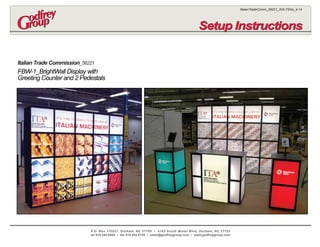
  • 1. P.O. Box 110527 Durham, NC 27709 • 4102 South Miami Blvd, Durham, NC 27703 tel 919.544.6504 • fax 919.544.6729 • sales@godfreygroup.com • www.godfreygroup.com ItalianTradeComm_56221_INS-7Shts_4-14 Setup InstructionsSetup Instructions Italian Trade Commission_56221 FBW-1_BrightWall Display with Greeting Counter and 2 Pedestals
  • 2. 1. The BrightWall Module consists of 3 Vertical 4-Section Units that remain intact. There are 2 End Frame Sections and 1 Mid Frame Section. Frame Sections 2 and 4 have removeable Horizontal Flanged Frames and a Light Fixture FrameAssembly that attach to the End and Mid Frame Sections. 2. The Frame Members connect via Snap-Fit Bullet Connectors. Simply line-up the Frame Holes/Bullet Connectors and push-in to engage. Note that the Frame pieces are labeled and must be positioned as shown. 3. Attach the Frame Members labeled L1 thru L4 to both the End and Mid Frame Sections as shown. This occurs at Frame Sections 2 and 4. 4. There are 4 Light Fixtures per FrameAssembly that clip onto the Light Fixture Vertical Frame. Refer to attached sheets for Light Fixture Cabling and Fixture Details. FBW-1_BrightWall Display FrameAssembly P.O. Box 110527 Durham, NC 27709 • 4102 South Miami Blvd, Durham, NC 27703 tel 919.544.6504 • fax 919.544.6729 • sales@godfreygroup.com • www.godfreygroup.com FBW-1_BrightWall_FrameAssy_4-14 LA LB LC L1 L2 L3 L3 L3 L4 L1 L2 L3 L3 L3 L4 4-26w Fluorescent Light Fixtures Clipped to Frame Light Fixture FrameAssembly 4 Vertical End Frame Section- Remains Intact 4 Vertical Mid Frame Section- Remains Intact Horizontal Flanged Frame Members- Sections 2 and 4 Frame Sect-1 Frame Sect-2 Frame Sect-3 Frame Sect-4 Frame Sect-5 Exploded Front View Key to Symbols Represents Frame Member Represents Fabric Panels To Engage: Line-Up Drill Hole With Bullet Plunger, Depress Bullet and Push Metal Tube onto Connector. To Disengage: Depress Bullet Plunger and Pull Metal Tube From Connector. Typical Snap-Fit Bullet Connectors Separating Velcro Detail Please note that when removing panels, use a thin tool such as a putty knife to separate the Velcro. Separating the panel Velcro by force can damage the panels.
  • 3. FBW-1_BrightWall_LtFixtureAssy_4-14 1. The BrightWall Module has (5) Light Fixture Frame Assemblies, (3) are fixed and (2) attach to the fixed Frame Sections. that attach to the End and Mid Frame Sections. 2. There are (20) 26 watt Fluorescent Light Fixtures. On each Light Bar Frame, (2) sets of Light Fixtures join together then attach to the Frame at the Metal Clips. Jumper Wires connect the Light Fixtures in-series. There are (2) Cable runs with (10) fixtures each. 3. The Power Cords on each run exit thru the grommets on the End Fabric Panels. FBW-1_BrightWall Display_Fluorescent Light Fixture Cabling P.O. Box 110527 Durham, NC 27709 • 4102 South Miami Blvd, Durham, NC 27703 tel 919.544.6504 • fax 919.544.6729 • sales@godfreygroup.com • www.godfreygroup.com Key to Symbols Represents Frame Member Represents Fabric Panels To Engage: Line-Up Drill Hole With Bullet Plunger, Depress Bullet and Push Metal Tube onto Connector. To Disengage: Depress Bullet Plunger and Pull Metal Tube From Connector. Typical Snap-Fit Bullet Connectors Separating Velcro Detail Please note that when removing panels, use a thin tool such as a putty knife to separate the Velcro. Separating the panel Velcro by force can damage the panels. LA LB LC L2 L2 Frame Sect-1 Frame Sect-2 Frame Sect-3 Frame Sect-4 Frame Sect-526w 26w 26w 26w 26w 26w 26w 26w 26w 26w 26w 26w 26w 26w 26w 26w 26w 26w 26w 26w Cable (10) Light Fixtures In-Series- Run Power Cord thru Grommet in Side Panel (2) Light Fixtures Join at the Center- Attach to Vertical Light Bar Frame at Metal Clips 6" Jumper Wire 6" Jumper Wire 24" Jumper Wire 24" Jumper Wire 24" Jumper Wire 24" Jumper Wire Power Cord Power Cord 6" Jumper Wire 6" Jumper Wire Cable (10) Light Fixtures In-Series- Run Power Cord thru Grommet in Side Panel Exploded Front View
  • 4. LA LB LC 2-Piece Sintra Top Panels with Air Vents- Velcro to Top of Frame Fabric-Covered Masonite End Panels Velcro to End Frames 20 Front and Back Backlit Graphic Panels- Velcro to Flanged Frames End Panel Grommet for Cabling Power Cord Frame Sect-1 Frame Sect-2 Frame Sect-3 Frame Sect-4 Frame Sect-5 Exploded Front View FBW-1_BrightWall_PanelAssy_4-14 1. Velcro the two Sintra Panels to the top of the BrightWall Display. 2. Velcro the Backlit Graphic Panels to the Flange Frames as shown at right. There are 20 Graphic Panels on the Front and Rear Side. 3. Velcro the Fabric End Panels to the BrightWall Frame. FBW-1_BrightWall Display PanelAssembly P.O. Box 110527 Durham, NC 27709 • 4102 South Miami Blvd, Durham, NC 27703 tel 919.544.6504 • fax 919.544.6729 • sales@godfreygroup.com • www.godfreygroup.com Key to Symbols Represents Frame Member Represents Fabric Panels To Engage: Line-Up Drill Hole With Bullet Plunger, Depress Bullet and Push Metal Tube onto Connector. To Disengage: Depress Bullet Plunger and Pull Metal Tube From Connector. Typical Snap-Fit Bullet Connectors Separating Velcro Detail Please note that when removing panels, use a thin tool such as a putty knife to separate the Velcro. Separating the panel Velcro by force can damage the panels.
  • 5. Fluorescent Light Fixture Assembly Using Jumper WiresUsing Jumper Wires Female Housing End Male Housing End Female Housing End Male Housing End Fluorescent Lights Jumper Wire Female Housing End Power Cord Connecting Lights in a Series Jumper Wire Jumper Wire Power Cord 1 2 3 4 P a r t s L i s t Power Cord Fluorescent Lights Jumper Wire Female/Male Adapter Female Housing End Male Housing End Velcro on Back Side Fluorescent Bulb AttachmentFluorescent Bulb Attachment Exterior Slot1 2 3 Twist the Light Housing so that it lines up with the Exterior Slot Slide the Fluorescent Bulb Prongs down into the Light Housings on both ends Twist the Fluorescent Bulb either direction until the Bulb Locks in place Twist Until Bulb Locks in Place Light Housing Joining Two FixturesJoining Two Fixtures 1 2 3 Joined Fixtures on a Light Bar Jumper Power Cord Female/Male Adapter Male Housing End Female Housing End Attach the Female End of the Adapter to the Male Housing End Then attach the Female Housing End to the Adapter Lights attached together with Female/Male Adapter Metal Clips - Alternate Attachment Method FluorescentLight_Update_10-13 P.O. Box 110527 Durham, NC 27709 • 4102 South Miami Blvd, Durham, NC 27703 tel 919.544.6504 • fax 919.544.6729 • sales@godfreygroup.com • www.godfreygroup.com
  • 6. Counter-PedestalAssy_4-14 Custom Greeting CounterAssembly_One Unit Custom Side PedestalAssembly_Two Units P.O. Box 110527 Durham, NC 27709 • 4102 South Miami Blvd, Durham, NC 27703 tel 919.544.6504 • fax 919.544.6729 • sales@godfreygroup.com • www.godfreygroup.com 1_Greeting Counter Frame The Counter Frame ships intact. Velcro (2) Fluorescent 22w Light Fixtures at each end. Cable the Power Cord thru the grommet into the center section. 4_Completed Greeting CounterAssembly 2_Attaching Graphic Panel Velcro the Graphic Panel to the face of the Front Fabric Panel. 5_Side Pedestal FrameAssembly The Pedestal Frame ships intact.Attach the (3) Fluorescent 22w Light Fixtures to the Center Vertical Frame. Cable the Power Cord thru the grommet in the Back Panel. 6_Completed Side PedestalAssembly- Front and Rear Views Velcro the PedestalTops centered on top of the Frame as shown. Install the IPDTF_ iPadTableTop Flanged Stands as detailed on the following sheet. Velcro the Backlit Graphic Panels to the Flanged Frame. 3_Attach Graphic Panels to Flanged Frame Sections Velcro the Backlit Graphic Panels to the Flanged Frames. 22w Fluorescent Light Fixtures Jumper Wire Power Cord Front Graphic Panel Front Fabric Panel Locking Swing Door Backlit Graphic Panels in Flanged Frames (3) 22w Fluorescent Light Fixtures Attached to Frame Jumper Wire Fabric-Wrapped Masonite Rear Panel
  • 7. SidePedestalAssy_4-14 Custom Side PedestalAssembly Cont: 9_Completed Side Pedestal Assembly- Front and Rear Views P.O. Box 110527 Durham, NC 27709 • 4102 South Miami Blvd, Durham, NC 27703 tel 919.544.6504 • fax 919.544.6729 • sales@godfreygroup.com • www.godfreygroup.com 7_iPAD TableTop StandAssembly_IPDTF (Fig.A) Secure iPad Stand to top of CounterTop using the Button-Hd Socket-Cap Bolts, Washer and Wing Nut fasteners at (3) places. (Fig. B) Remove the acrylic cover using the small tamper-proof key provided. Place tablet inside and reassemble unit. If Ball Joint loosens on back, use the large tamper-proof key to retighten it securely. 8_iPAD TableTop StandAssembly_Rear and Front View