Conventional and emerging converter technologies in hvdc power transmission s...
High Voltage Compact Pulser Specs and Applications
1. High Voltage Compact Pulser
M7 Electro-Optics, LLC · 13720 Shoreline Court East · Earth City, MO · (314) 368-6120 ·www.m7eo.com
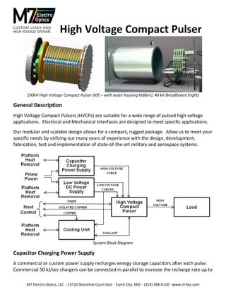
100kV High Voltage Compact Pulser (left – with outer housing hidden), 40 kV Breadboard (right)
General Description
High Voltage Compact Pulsers (HVCPs) are suitable for a wide range of pulsed high voltage
applications. Electrical and Mechanical Interfaces are designed to meet specific applications.
Our modular and scalable design allows for a compact, rugged package. Allow us to meet your
specific needs by utilizing our many years of experience with the design, development,
fabrication, test and implementation of state-of-the-art military and aerospace systems.
System Block Diagram
Capacitor Charging Power Supply
A commercial or custom power supply recharges energy storage capacitors after each pulse.
Commercial 50 kJ/sec chargers can be connected in parallel to increase the recharge rate up to
2. 2
M7 Electro-Optics, LLC · 13720 Shoreline Court East · Earth City, MO · (314) 368-6120 ·www.m7eo.com
200 kJ/sec. These are typically 85% efficient. A custom, 200 kJ/sec charger can be repackaged
for a particular application. Since the custom charger is designed for specific operating
conditions, efficiencies over 90% can be achieved.
Connection to the HVCP is via a 50 foot, rugged, airborne qualified high voltage cable.
Low Voltage DC Power Supply
Standard commercial or custom designed DC supplies provide 125 V, 1.2 A (150 W) and 24 V,
3.0 A (72 W). These power supplies are typically 90% efficient.
Connection to the HVCP and Cooling Unit is via 50 foot, rugged, airborne qualified cables.
Cooling Unit
A dedicated Fluorinert cooling loop removes HVCP waste heat. Fluorinert inhibits high voltage
flashover in the coolant, but is not as effective removing waste heat as other media, such as
water. High efficiency heat exchangers in the HVCP stages provide for waste heat removal.
Heat is transferred to the host platform via a liquid-to-liquid heat exchanger, an air-to-liquid
heat exchanger or a coldplate mounted to a cooled surface.
The Cooling Unit must be located within 10 feet of the HVCP to keep pressure drops low.
High Voltage Transmission to Load
The High Voltage Transmission Line is likely the largest contributor to load stray capacitance.
Transmission Line options are a high voltage cable or a high voltage conduit. High Voltage
Cables capable of carrying 100 kV are typically 70 to 100 pf per foot and can store considerable
energy. Conduits can be designed with a capacitance of less than 20 pf per foot, but they are
less flexible and may be larger diameter than cables.
High Voltage Compact Pulser (HVCP)
The HVCP is designed to meet system electrical and mechanical interface requirements as well
as environmental temperature, vibration and shock specifications. Compactness requires
electrostatic analysis modeling and strategically placed field shapers to keep maximum electric
fields below breakdown limits of the insulating medium. Field strengths are checked in air at
lower voltages with a corona finder camera system to ensure adequate margins.
The HVCP utilizes commercially available, high voltage solid state switches operated in series
groups. High voltage SiC switches packaged to replace a series group of commercial switches
are being developed under a Cooperative Research and Development Program. The SiC
devices allow the HVCP to be smaller, more efficient, with an expanded operating range.
3. 3
M7 Electro-Optics, LLC · 13720 Shoreline Court East · Earth City, MO · (314) 368-6120 ·www.m7eo.com
A key feature of the HVCP is that external and internal faults are detected and stored energy is
safely discharged without causing cascading failures or damaging the load.
HVCP Stage
Maximum pulsewidth is a function of the output current. HVCP stages can be optimized for
output current and pulsewidth requirements. Output currents up to 200 A can be achieved.
Maximum 100 kV Output Pulse (10 A left, 20 A right)
In addition to limiting output voltage rise time, load stray capacitance effects maximum pulse
rate and HVCP efficiency.
Recharge Rate for 100 kV, 10 A, 11% Pulse Duty Factor (PDF)
4. 4
M7 Electro-Optics, LLC · 13720 Shoreline Court East · Earth City, MO · (314) 368-6120 ·www.m7eo.com
HVCP Efficiency vs Pulse Repetition Rate (PRF) for 100 kV, 10 A ·, 11% Pulse Duty Factor (PDF)
PARAMETER VALUE
Output Voltage 100 kV
Output Current 10 A
Peak Output Power 1 MW
Average Output Power 25 kW
Pulse Frequency Single Shot to 4 kHz
Pulse Duty Factor 11.0%
Burst Duty 22.7%
HVCP Dimensions 20” Diameter x 25” Length
Volume and Weight 7850 in3 , 250 lbs
100 kV, 10 A HVCP Specifications
100 kV, 10 A Performance as PRF Varies
Output voltages and currents up to 300 kV and 200 A can be achieved. Pulse parameters will
depend upon the load characteristics and fault protection requirements, the connection to the
load, and the volume available for the HVCP. Additional energy storage may be required at
the Capacitor Charger input to reduce the peak power demand from the prime power source.