Recommended

Recommended
More Related Content
What's hot
What's hot (20)
Viewers also liked
Viewers also liked (20)
Similar to Poster v3
Similar to Poster v3 (20)
Poster v3
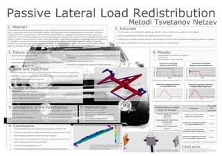
- 1. Passive Lateral Load Redistribution A passive lateral load redistribution device (PLLR) is designed with the help of concepts and is discussed by means of static, motion and stress and sustainability analysis. The properties of the simplified pendulum have been calculated using the aid of manual calculations, Microsoft Excel and SolidWorks. Legal aspects of implementing the device are examined in terms of racing regulations as well as possible patent infringement. Results from the investigations show the device is useful in many cornering situations due to possibility of adjustment through its comprising springs and dampers. It is possible to use and manufacture the device through some additional refinement aimed at suiting it for specific vehicles and reducing weight while maintaining stiffness. A methodology foundation for further improvement has been laid out, although the complete implementations and the legal status have further scope for investigation. 1. Abstract There needs to be a method for stabilizing a vehicle in left and right turns as well as in the straights. Active mass distribution devices are explicitly banned from racing Offering the possibility of having different roll stiffnesses in both roll directions without impacting stiffness on straights To create a foundation for further improvement in terms of aerodynamics. 2. Rationale Dynamic performance assessment Static performance assessment Second order integral equations and superimposition of driving forces 3. Nature of the problem Increasing the similarity between a double wishbone suspension and a simulation Addressing implementation issues Reduction in complexity for build and simulation purposes Design a method for checking the presence of benefits of having a passively actuated mass Determine a maximum load a chassis and spring configuration can move to stabilise itself Design a mechanism which can achieve this Evaluate the practical constraints associated under which the mechanism is useful 4. Aims and objectives Achieving the aims and objectives Modelling a single axle representation (modelling a full vehicle simulation given enough time) Using a variety of new software skills Performing a dynamic suspension simulation in excel 5. Scope of the investigation Inherent size requirement of the mechanism High stress areas Crash safety not investigated Very high resistance to single wheel bump 6. Limitations of the investigation Slider design incompleteness Shear forces on fasteners not tested Testing not accurate enough Lack of practical testing 1. Desired system response 2. Calculation of motion ratios 3. Solid design and adaptation to practical constraints 4. FEA testing and improvement 5. Sustainability assessment and improvement 7. Methodology Improvement of time taken for system to come to rest Improvement of centre of gravity 8. Results Plot of double mass simulation with sudden force application Plot of the single mass simulation with sudden force application Plot of double mass simulation with example cornering forces Plot of single mass simulation with example cornering forces Simulation Time until rest (seconds) Constant force with sudden application and halt (PLLR) 12.282 s Gradual force application and halt in a racing condition (PLLR) 14.683 s Constant force with sudden application and halt (single mass) 16.122 s Gradual force application and halt in a racing condition (single mass) 16.881 s Vertical forces on wheel closest to the apex Cornering wheel normal force with PLLR 471.972 N Cornering wheel normal force without PLLR 422.997 N Normal force improvement 48.975 NThe system allows the use of softer coil springs and anti roll bar in roll The system may allow two directional damping and spring resistance in roll Wheel loading improvement under cornering is marginal Improvement of wheel loading may allow the use of more body roll for the driver, making the vehicle more predictable Current size and packaging is an issue Possibility of improving aerodynamic performance using the mechanism 9. Conclusions Time taken to reach stable equilibrium after two types of excitations Normal forces on tyre closest to apex during steady cornering Upper section of the suspension simplification pendulum. The purple plane is the equilibrium Part of the strength, weight and sustainability optimisation is stress testing using FEA. At 3000N load the maximum stress is 233 Mega Pascals which guarantees a safety factor of nearly 3. Consequently, the deflection is marginal Basic design suggestion for the device. Movement is limited on the side of the diagonal member between the second cantilever and the centre part Metodi Tsvetanov Netzev Bolton, D., 2006. Mechanical Science. 3rd ed. Chennai: Blackwell Publishing. Oberg E, J.F.H.H.R.H., 2004. Machinery's Handbook. 27th ed. New York: Industrial Press Inc. S, K. & S, S., 2009. Manufacturing Engineering and Technology. 6th ed. Indianapolis: Pearson. Smith, C., 1978. Tune to Win. 1st ed. Fallbrook: Aero Publishers Inc. Cited work